CNC Machining for Robotics: Custom Robot Parts, Design, and Manufacturing Guide
23 min
- Why Robotics Requires CNC Machining
- Where CNC Machined Parts Are Used in Robotics
- CNC vs 3D Printing vs Casting for Robot Parts
- Design Considerations for CNC-Machined Robot Parts
- Material Selection for Robotics CNC Machining
- Manufacturing Strategy for Robotics Parts
- How Manufacturing Decisions Create Field Failures in Robot Parts
- Cost Drivers in CNC Machining for Robotics
- How to Choose CNC Machining Services for Robotics
- FAQs About CNC Machining for Robotics
CNC machining for robotics refers to the use of precision CNC manufacturing to produce critical robotic components such as joints, frames, and motion interfaces. These machined parts for robotics are designed to maintain tight tolerances, structural stability, and repeatable motion under load.
In CNC manufacturing robotics, machining quality directly affects positioning accuracy, system stiffness, and long-term performance.
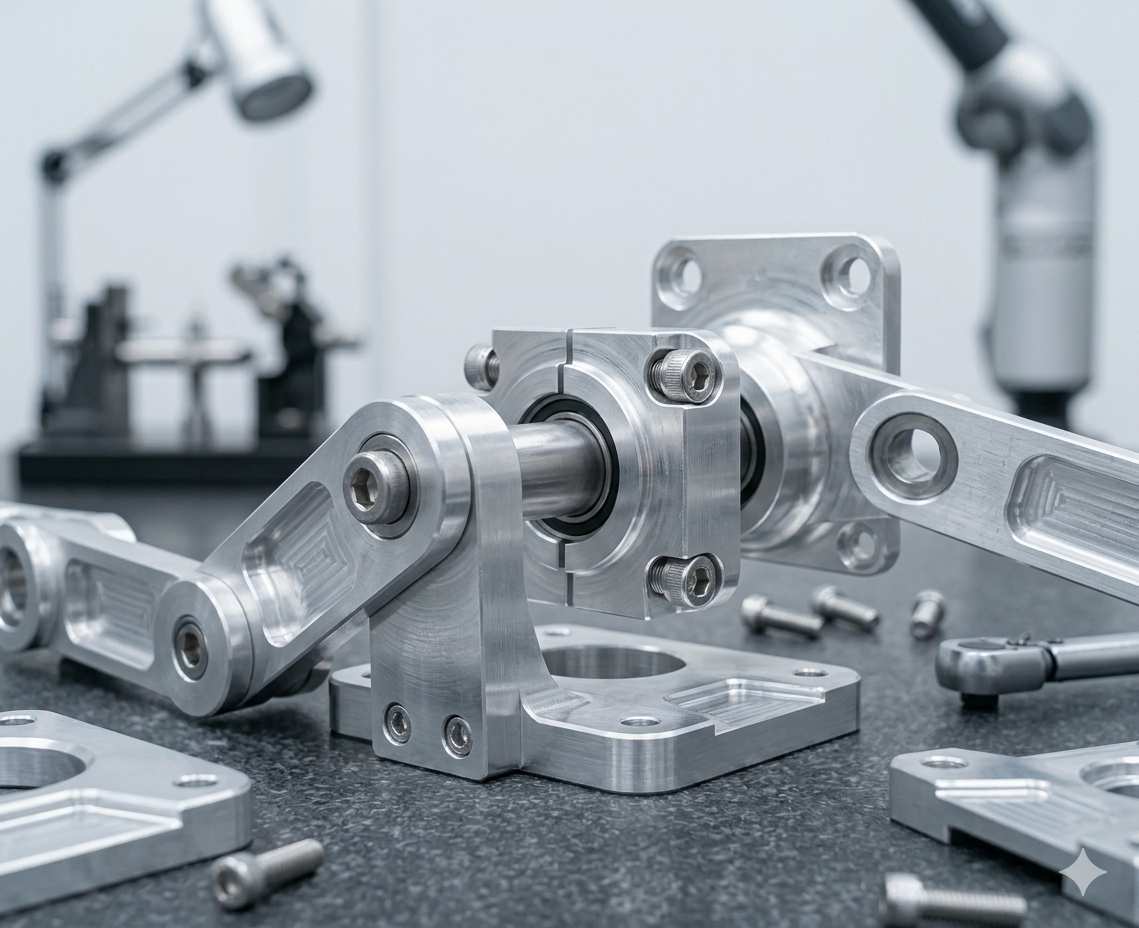
(AI generated) CNC machined robot joint components
You probably interact with a machine using some form of robotic logic every single day. Even simple devices like robotic vacuum cleaners reflect this broader shift toward automation across logistics, healthcare, and manufacturing. All that precise, repetitive movement is built on a foundation of extremely tight mechanical tolerances. Manufacturing these assemblies requires controlled machining processes, where CNC defines the geometry that governs motion accuracy.
CNC machining for robotics focuses on a single objective: maintaining predictable motion under load. That means controlling geometry, material behavior, and assembly fit so the robot performs consistently across both initial operation and long-term use.
While CNC systems were advancing precision within controlled machining environments, industrial robots like the Unimate were starting to handle the heavy lifting. The real breakthrough happened when we put CNC-level brains into robotic arms, improving flexibility in handling and positioning tasks, though not replacing the precision of dedicated CNC machine tools.
Key Takeaways About CNC Machining for Robotics
Precision and Motion: High-quality motion starts with critical interfaces. If bearing seats or rail mounts deviate beyond their functional tolerance range (often within a ±0.01–0.05 mm range for precision interfaces, depending on system requirements), errors compound into vibrations or missed positions. Focus precision on where motion originates rather than chasing tight tolerances on every single surface.
Stiffness over Strength: A robotic arm needs predictable deflection, not just raw power. If the geometry is too thin, the frame will flex under load, shifting your calibration over time.
Material Strategy: 6061-T6 aluminum is the standard for its balance of cost and stability. Use 7075-T6 when you need a better stiffness-to-weight ratio, and save steel for high-wear areas like shafts or contact points. (Learn the difference between 6061 vs 7075)
Milling vs. Turning: Most robotic assemblies rely on CNC milling to ensure flatness and hole alignment across multiple faces. Turning is usually reserved for the rotational components (shafts, pins, spacers).
Functional Tolerancing: Avoid "spec creep." Tightening tolerances below typical functional ranges (around ±0.02–0.05 mm) often increases cost without improving system performance.
The Fixturing Factor: A part can look perfect on the machine, but warp once the clamps are released. Proper fixturing prevents internal stresses from ruining your alignment during final assembly.
Surface Integrity: Rough finishes are bearing killers. Controlled surface finishes are mandatory anywhere parts slide or rotate to prevent friction from degrading the system.
Tolerance Stack-up: A robot is a chain of parts. Even if every individual component passes inspection, their combined tolerances can cause total misalignment. Design for the "stack," not just the part.
Design for Manufacture: Deep pockets and sharp internal corners slow down the spindle and drive up costs. Keeping geometry clean reduces tool wear and gets your parts off the machine faster.
Why Robotics Requires CNC Machining
Precision & Repeatability Requirements
Robots don’t fail in dramatic ways. They drift.
A joint goes slightly off by a fraction, something like 0.02 mm, and it doesn’t look like much on paper. In real motion, that becomes a missed pick, a shaky path, or a tool that doesn’t land where it should.
That’s why CNC robotics setups rely on CNC parts for anything tied to alignment. Bearing seats, motor mounts, and rail interfaces are not “close enough” features. They directly define alignment behavior across cycles.
Repeatability is often more critical than peak accuracy. A robotic system must return to the same position under load across repeated cycles. This depends not only on dimensional precision but also on surface roughness, contact stress distribution, and wear behavior at functional interfaces.
Load-Bearing and Dynamic Stability Needs
Robots are never really static. They accelerate, stop, change direction, repeat. That constant motion puts stress everywhere, not just where the load is obvious.
At this stage, machining decisions directly affect structural behavior. A part can look strong in CAD and still flex under real movement. Especially in aluminum frames, where weight is low but geometry carries stiffness.
Most of the time, 6061-T6 is commonly used due to its machinability and stable behavior under moderate load and thermal variation, especially in non-critical structural components. It machines well and holds shape predictably. When things get more aggressive, 7075-T6 comes in. Steel shows up only where wear actually happens, not everywhere by default.
The key is controlling deflection. If a part moves even slightly under load, the whole calibration chain shifts with it.
And this is something people miss early on. Stress doesn’t just sit in the part. It shows up later during the operation.
Manufacturing Trade-offs: CNC, 3D Printing, and Casting
3D printing looks tempting until you try to use printed parts in actual motion systems.
Mechanical properties in additive manufacturing depend on the process. While FDM parts show anisotropy along layer lines, industrial processes such as SLS or metal powder bed fusion can achieve more uniform properties, though precision interfaces such as bearing fits and sealing surfaces still require secondary CNC machining.
Casting has its own limits. It makes sense at scale, but it locks you into tooling early. If something changes in design, you’re back to rework or retooling. That slows everything down. Here's a guide on casting defects.
CNC stays in the middle for a reason. It gives control. You cut exactly what you need, nothing more, nothing locked in early. That flexibility is what keeps robotic CNC machining services relevant even as other methods evolve.
In practical CNC robotics applications, different types of machined parts for robotics serve distinct roles depending on motion, load, and system integration requirements. Understanding where CNC machining is applied helps define tolerance strategy, material selection, and manufacturing approach.
Where CNC Machined Parts Are Used in Robotics
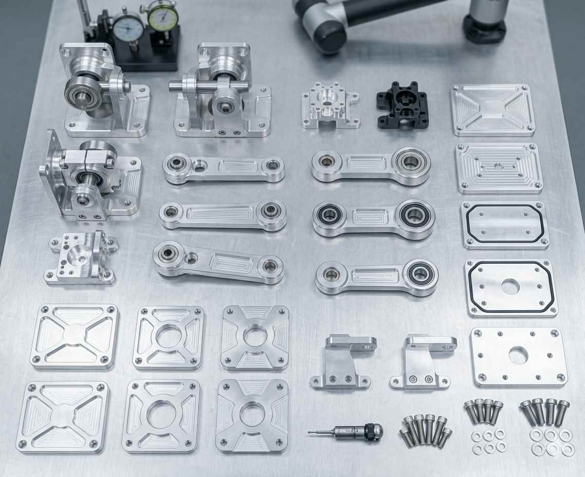
(AI generated) Various CNC machined parts used in robotic systems
Motion Systems (Joints, Actuators, Linkages)
Joints, actuator mounts, and linkages carry constant motion load. Any small deviation in geometry directly affects how smooth that motion feels. If a bearing seat is off or a motor mount isn’t perfectly aligned, the system doesn’t just lose efficiency. It introduces internal misalignment and friction.
That’s why machining robotics parts for motion systems usually focuses on tight fit control and repeatable alignment. The system must maintain consistent motion across repeated cycles without introducing play or vibration.
In most setups, precision CNC machining for robotics here is non-negotiable. These are the components that define how stable the entire robot feels under load.
Structural Frames & Load-Bearing Assemblies
Frames look simple until they start flexing.
Structural assemblies carry the full system load, plus dynamic forces from motion. Even a small deflection in a frame can shift alignment across the whole system. That’s where CNC manufacturing robotics decisions matter more than design visuals.
Aluminum frames are common in custom robot parts because they balance weight and stiffness. But the real performance comes from how those parts are machined, not just the material itself.
Flatness, hole alignment, and consistent wall geometry decide whether the structure stays stable or slowly drifts out of calibration over time.
End Effectors & Precision Interfaces (Sensors/Tools)
End effectors are where the robot actually interacts with the world.
Grippers, tool mounts, sensor brackets. These parts don’t carry heavy loads, but they demand accuracy. A small misalignment here turns into a bigger error at the tool tip.
This is where machined parts for robotics need clean interfaces. Tool mounting faces, sensor alignment surfaces, and connector points all need stable geometry so the system reads and reacts correctly.
In robotic CNC machining services, this section is usually where tolerance control gets strict, not for strength, but for alignment consistency.
Enclosures & Integration Housings
Enclosures are often underestimated in design, yet they directly affect system stability and serviceability.
They protect electronics, control wiring, and internal systems from vibration, dust, and mechanical stress. If the housing isn’t properly machined, mounting points don’t align, and internal components start shifting under operation.
CNC machining for robotics housings is less about extreme precision and more about predictable fitment. Everything needs to assemble cleanly without forcing stress into electronics or connectors.
Good enclosure design also reduces maintenance issues later. If access, mounting, and alignment are clean from the start, the system stays serviceable instead of becoming a teardown problem.
Robotic systems fail at the interfaces, and interfaces are only as good as the machining behind them. At JLCCNC, CNC parts for robotics go through engineering review before production, so tolerance allocation, surface finish at contact faces, and material behavior under load are considered before your parts run. Upload your files and get a quote from engineers who understand what the assembly is actually trying to do.

Precision CNC Machining Service
Professional manufacturing, fast turnaround, and quality assurance.
CNC vs 3D Printing vs Casting for Robot Parts
Robotic systems do not fail on manufacturing theory. They fail when geometry, stiffness, and repeatability stop matching real motion conditions. CNC robotics workflows, additive manufacturing, and casting all solve the same problem from different constraints. The decision is not about preference. It is about how the part behaves under load, how stable it stays over time, and how reliably it can be produced at scale.
| Evaluation Criteria | CNC Machining | 3D Printing | Casting |
|---|---|---|---|
| Dimensional stability | High stability due to controlled material removal and predictable cutting behavior | Depends on layer adhesion and orientation, can shift under load or heat | Stable after cooling, but affected by shrinkage variation and mold accuracy |
| Mechanical performance | Strong isotropic properties aligned with the base material, like aluminum or steel | Direction-dependent strength, weaker along layer lines under cyclic load | Good bulk strength, but internal porosity risk affects fatigue life |
| Precision and tolerance control | Tight control on critical interfaces like bearing seats and mounting faces | Fine features are possible, but post processing often required for functional fits | Moderate precision usually requires secondary CNC finishing |
| Surface finish quality | Consistent machined finish suitable for moving assemblies and fits | Layer texture visible, smoothing required for functional surfaces | Rougher surface requiring machining for sealing or alignment faces |
| Load-bearing suitability | Reliable for structural frames, joints, and motion systems in CNC robotics | Limited for high-load or high-cycle robotic components without reinforcement | Suitable for static loads but inconsistent under dynamic robotic motion |
| Production repeatability | High repeatability across batches in CNC machining workflows used in robotic systems | Variable between prints depending on process control and material batch | Consistent once mold is stable, but costly to modify after setup |
| Design flexibility | Moderate flexibility, constrained by tool access and geometry | Very high design freedom, including internal lattices and complex shapes | Low flexibility due to mold constraints and setup cost |
| Cost behavior | Efficient for low to medium-batch custom robot parts | Cost-effective for prototypes and low-volume iteration | Cost-effective only at high volume once tooling is justified |
| Assembly reliability | High alignment accuracy improves robotic CNC machining services integration | May require post-machining for assembly fit accuracy | Requires machining for precision interfaces before assembly |
Here’s a deeper look into 3D printing vs CNC machining and casting vs CNC machining. In most CNC robotics scenarios, CNC machining remains the preferred solution for precision-critical and load-bearing components, while additive manufacturing and casting serve more specialized roles.
If the robot part sits in a motion path, carries a load, or defines alignment, CNC machining is typically preferred for load-bearing and precision-critical components, while other methods may be more suitable for prototyping or complex internal geometries. If the goal is rapid iteration or complex internal geometry without strict load demand, additive manufacturing fits better. If production volume is high and geometry is locked, casting becomes viable at higher volumes, typically combined with CNC finishing to control critical interfaces and dimensional accuracy.
Design Considerations for CNC-Machined Robot Parts
Robot design breaks the moment when geometry and function stop agreeing with each other. A part can look correct in CAD and still fail in assembly because the way it is used is not reflected in how it is defined. CNC machining for robotics only works cleanly when functional intent drives every dimension, not the other way around.
Function-Driven Tolerance Allocation
Tolerances in robotic CNC machining services are not uniform. They should follow function, not convention.
Critical interfaces like bearing seats, rail mounts, and motor couplings carry most of the alignment responsibility. These areas need tighter control because even small deviations change motion behavior. Non-critical features such as covers, pockets, or clearance zones should stay relaxed to avoid unnecessary machining time and inspection load.
The key decision is not how tight you can go, but where tightness actually affects system behavior. Over-constraining everything increases cost and introduces hidden assembly stress without improving performance.
Balancing Weight Reduction and Structural Rigidity
Lightweight design is useful only until it starts changing geometry under load.
In CNC manufacturing robotics, reducing mass often improves motion efficiency, but aggressive material removal can weaken structural paths. The real constraint is not the weight itself, but the deformation under dynamic conditions.
Good design keeps load paths direct and avoids removing material where force transitions happen. Thin sections can work if they are supported properly, but unsupported spans create flex that shows up during operation, not during inspection.
The goal is controlled stiffness, not maximum reduction. Every cut in geometry should still preserve predictable behavior under motion.
Interface Alignment and Assembly Repeatability
Assembly is where most design assumptions fail.
If interfaces do not naturally guide alignment, every assembly becomes a correction process. That leads to inconsistent positioning and extra stress in fastened joints.
Good design uses geometry to force repeatability. Mating features should self-locate, not rely on manual adjustment. When parts are assembled multiple times, they should return to the same position without variation.
This is not about tighter tolerances everywhere. It is about defining stable reference points so the entire system aligns the same way every time it is built or serviced.
Material Selection for Robotics CNC Machining
Material choice in CNC machining for robotics is not a catalog decision. It is a response to how the robot behaves under load, heat, and continuous motion. A part might be structurally strong on paper but still fail in practice if it deforms, wears unevenly, or shifts dimensionally during operation. In machining robotics, the material has to match the real operating environment, not just the CAD model.
| Material Category | Mechanical Behavior | Wear Performance | Thermal Response | Typical Use in Robotics |
|---|---|---|---|---|
| Aluminum | Lightweight, moderate stiffness, good machinability | Moderate wear resistance, surface dependent | Expands moderately with heat | Frames, brackets, motion structures |
| Steel | High stiffness, high strength, heavier mass | High wear resistance | Stable under higher temperatures | Shafts, joints, load critical components |
| Engineering Plastics | Flexible, vibration-damping, lower stiffness | Low to moderate wear, depending on grade | Sensitive to temperature variation | Covers, spacers, non-structural parts |
Manufacturing Strategy for Robotics Parts
Robotic parts don’t fail at the design stage. They fail when manufacturing stops protecting geometry between operations. The real objective in CNC machining for robotics is straightforward: maintain alignment, stiffness, and surface behavior from raw stock to final assembly.
Material Removal vs Geometry Stability
Roughing removes material quickly, but also redistributes residual stress, which can cause part deformation once clamping forces are released. If too much material is removed near functional areas early on, the part shifts later, and finishing starts chasing distortion instead of defining geometry.
At this stage, accuracy is not the goal. Stability is. Critical features on machined parts for robotics are intentionally left with stock, so finishing cuts define the final dimensions, not the roughing pass.
Finishing is where control actually matters. It locks in tolerances, refines mating surfaces, and sets functional interfaces like bearing seats and mounting faces. This separation is what keeps precision CNC machining for robotics consistent across repeated builds.
Controlling Alignment Across Multiple Setups
Most robotic components cannot be completed in a single setup. Once a part is reoriented, every new setup introduces a potential shift in reference.
The real control point is datum discipline. All operations must reference the same geometry logic. If that breaks, small positional offsets accumulate across setups, often within the 10–50 μm range per operation.
Well-planned workflows in robotic CNC machining services avoid this by keeping every setup tied back to stable reference faces. The part never “restarts” its coordinate system. It continues.
That is what prevents cumulative alignment drift in complex geometries used in CNC manufacturing robotics systems.
Surface Condition as a Functional Parameter
After machining, the part is not functionally complete yet. Surface condition still decides how it behaves under real load.
Surface treatment is selected based on function, not appearance. Some components need corrosion resistance, others need reduced friction, and some require harder surfaces for repeated contact.
Even small surface deviations (e.g., Ra variation or waviness) can affect seating behavior and contact stability. In custom robot parts, this becomes critical at interfaces where motion or load transfer happens repeatedly.
A part is only production-ready when its surface behavior and geometry both match the operating conditions it will face in the system.
How Manufacturing Decisions Create Field Failures in Robot Parts
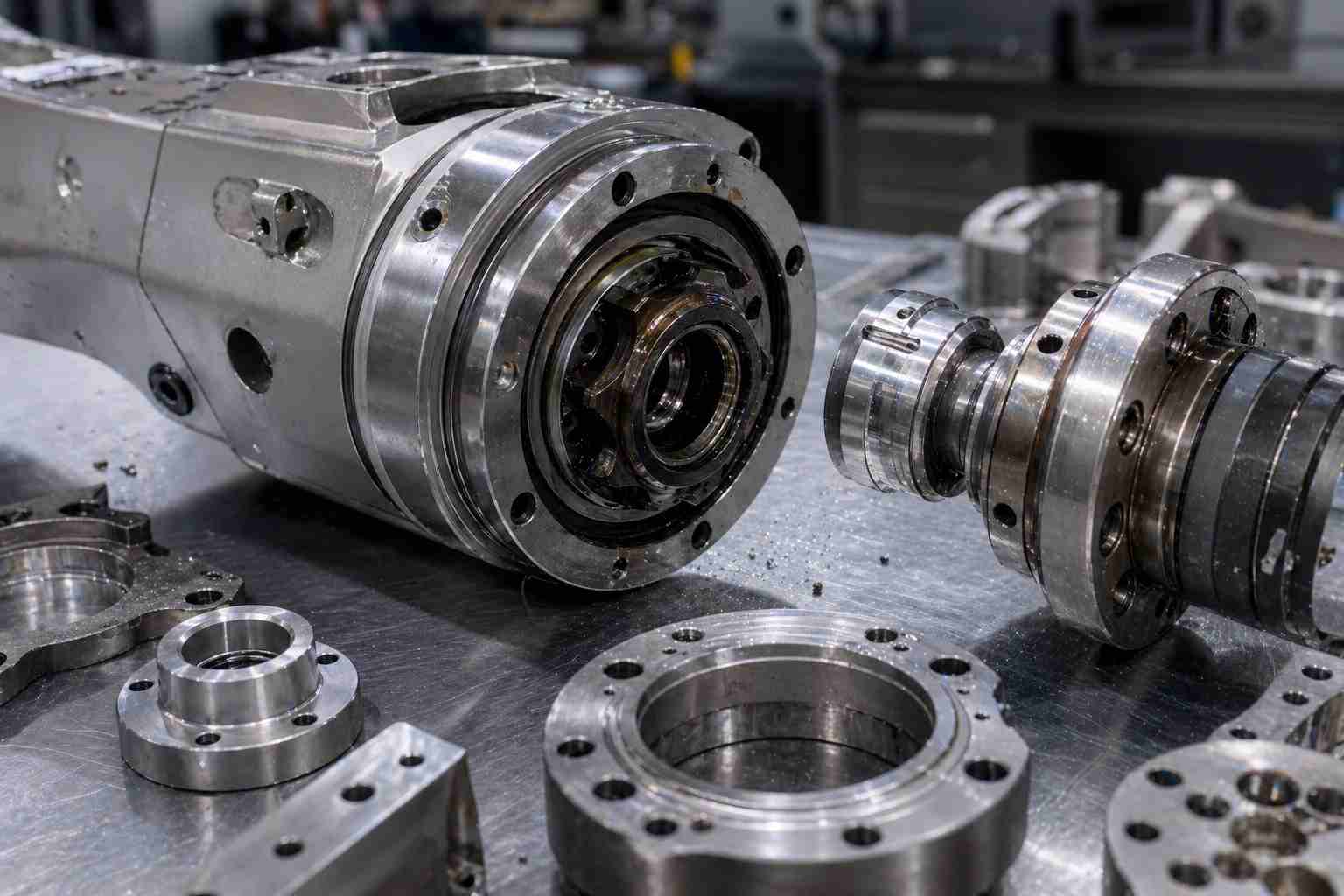
(AI generated) Disassembled precision robotic joint with CNC machined components
Robot failures rarely announce themselves. They drift in, gradually, through accumulated small deviations that interact over thousands of motion cycles until performance drops below acceptable limits.
Understanding where that starts requires looking at both sides: what happens during manufacturing, and how those decisions play out in operation.
Tolerance Stack-Up
Individual parts pass inspection. The problem appears at the assembly. Each machined interface carries its own tolerance window, and when multiple components come together, joints, mounts, and linkages. These small variations accumulate across the full structure. The result is a shifted reference path where motion no longer follows intended geometry, showing up as positional error at the end effector, uneven load transfer, or preload in joints that were never designed in.
This isn't a random defect. It traces back to how tolerances were allocated during design. Over-constraining non-critical features or under-defining functional datums increases the likelihood of alignment drift once the system is assembled. In CNC machining for robotics, where motion accuracy depends on layered mechanical precision, a single out-of-tolerance dimension is rarely the problem. It's how many "acceptable" dimensions combine into a functional one.
Thermal Effects
Heat during machining leaves residual stress in parts. When those components later encounter operational temperatures or ambient variation, that stress releases unevenly, causing a slight distortion that wasn't present when the part passed dimensional inspection.
In operation, the problem continues. Materials expand and contract with temperature changes, and that movement is rarely uniform across a full assembly. Long structural members and tightly assembled modules are most sensitive. Over repeated thermal cycles, alignment points shift gradually, not enough to see, but enough to affect calibration and repeatability in precision systems. By the time it's diagnosed, the source is usually a material selection or geometry decision made early in the design process.
Wear and Loosening
Wear starts at contact surfaces where motion or load repeats. Initially, it's microscopic, a slight movement between mating surfaces that reduces clamping stability and introduces clearance where none was intended. As cycles accumulate, that microscopic movement becomes measurable in joints, shafts, and sliding interfaces.
The rate at which this happens is largely determined by two design decisions: surface quality at the interface and how load paths are defined. If contact areas aren't properly distributed or fasteners are working against dynamic load instead of stabilizing it, wear accelerates well ahead of expected service life. In systems relying on precision CNC machining for robotics, even small increases in clearance directly affect motion repeatability and control accuracy. The system looks intact geometrically, but has lost the positional consistency it was built for.
Deformation Under Load
Parts can change shape during machining. Thin sections and long spans tend to deflect under cutting forces. Even small deflection shifts alignment in assemblies where multiple components reference fixed geometry. A part that held its dimensions on the inspection table can behave differently once it's carrying a load in a running system, and if that deflection wasn't accounted for in the design, the machined accuracy becomes functionally irrelevant.
Cost Drivers in CNC Machining for Robotics
Cost in robotic machining is not mainly a pricing issue. It is a consequence of engineering decisions that change machining time, setup effort, and the probability of rejection. Once those variables shift, the quote shifts with them. Industry breakdowns consistently show that machining time, setup, and tolerance control dominate total cost rather than raw material price. In real machining environments, factors such as tool wear, spindle runout, and thermal drift introduce process variation that must be compensated during machining and inspection.
Tolerance Requirements vs Machining Time
Tighter tolerances directly slow down production because they force controlled cutting, slower feed rates, and additional inspection loops.
A part held at standard industrial tolerance may run quickly, but once functional interfaces like bearing seats or alignment holes move into tight tolerance zones, cycle time increases sharply. Industry data shows precision tolerance requirements can significantly increase machining time due to slower cutting and added inspection steps.
The cost impact is not evenly distributed. One tight feature can be manageable, but multiple tight features across an assembly multiply machining time and increase rejection probability during inspection.
Geometry Complexity and Multi-Axis Machining
Complex geometry increases cost because it increases both machine movement and setup count.
Deep pockets, undercuts, and multi-face features often require additional setups or multi-axis toolpaths. Each setup introduces programming time, fixturing time, and alignment risk. Industry guides consistently identify multi-setup and complex geometry as direct cost escalators in CNC production.
In robotics parts, this becomes more sensitive because geometry is not only structural but also functional. A small accessibility constraint can force slower machining strategies or specialized tooling, which increases cycle time per part.
Batch Size, Repeatability, and Scrap Risk
Batch size changes how cost is distributed, but not how machining effort is generated.
Low-volume production concentrates setup and programming costs into each unit. A single setup can take a significant portion of the total cost, regardless of whether you make one part or many.
As quantity increases, unit cost drops because setup is amortized. However, repeatability becomes the key factor. If process variation exists, scrap rates increase and can erase volume savings.
Scrap risk in robotic parts is usually tied to tight functional tolerances and multi-step operations. Small deviations during setup or machining propagate into assembly misfit, increasing rejection rates instead of usable output.
How to Choose CNC Machining Services for Robotics
Selecting a machining supplier for robotics is less about equipment size and more about how reliably they can deliver parts that behave correctly in motion systems. Most failures don’t come from manufacturing inability. They come from inconsistent process control and weak engineering judgment.
Verifying Capability Beyond Machine Lists
Machine specifications don’t guarantee production capability.
What matters is repeatable performance on functional geometry. Alignment accuracy, stable tolerances, and consistency across batches are what actually define capability. A supplier can have modern equipment and still struggle with tight interfaces if process discipline is weak.
Practical verification is simple:
- Ask for tolerance inspection reports from real production parts
- Review examples of assemblies, not just individual components
- Check how they handle functional features like bearing seats, rails, and mating faces
Capability is proven through output stability on machined parts for robotics, not through equipment lists or marketing claims.
Engineering Support and DFM Feedback
A capable supplier does not passively accept design files.
They actively review manufacturability before production starts. This includes identifying unnecessary tight tolerances, inaccessible tool regions, and geometry that increases machining risk without functional benefit.
Strong design feedback reduces rework, improves assembly fit, and shortens machining time. Weak suppliers skip this step and move directly to execution, which pushes all risk back to the customer.
In precision CNC machining for robotics, early design correction is often the difference between stable assemblies and repeated adjustment during integration.
Lead Time Consistency and Quality Control
Speed is less important than predictability.
Robotics development depends on synchronized timelines for machining, assembly, and testing. If delivery varies, the entire validation cycle becomes unstable.
Quality control should be measurable, not assumed. That includes:
- Defined inspection points during production
- Clear rejection criteria before shipment
- Traceable measurement records for critical features
In robotic CNC machining services, consistency in delivery and inspection matters more than occasional fast turnaround. One unstable batch can delay system calibration and testing far more than a slightly longer but reliable lead time.
The difference between a robotic system that holds calibration and one that drifts comes down to manufacturing decisions made before the first part is cut. Tight tolerances on functional datums, correct surface finish at interfaces, material matched to the thermal and load environment, none of that happens by accident.
JLCCNC machines robotic components with engineering review built into the process, not bolted on at inspection. If your application depends on reliable fit, stable performance, and controlled delivery, upload your CAD file to get a fast quote starting from $1, with lead times as short as 3 days.
CNC machining for robotics is ultimately about controlling how parts behave in motion, not just how they look on a drawing. From tolerance allocation to material selection, every machining decision contributes to system accuracy, repeatability, and long-term reliability.
Precision CNC Machining Service
Professional manufacturing, fast turnaround, and quality assurance.
FAQs About CNC Machining for Robotics
Q: What Tolerance Is Typically Required for Robot Parts
Tolerance depends on function, with critical features like bearing seats typically in the ±0.01–0.05 mm range, while non-functional geometry can be looser.
Q: Is CNC Machining Suitable for Low-Volume Robotics Production
Yes, CNC is ideal for low-volume robotics because it allows fast iteration without tooling delays.
Q: Can Complex Robot Parts Be Machined in One Setup
Rarely, most functional robot parts require multiple setups to maintain tool access and feature accuracy.
Q: How to Reduce Cost Without Losing Precision
Focus tight tolerances only on functional features and simplify geometry where it doesn’t affect performance.
Popular Articles
• CNC Machining in the Medical Industry
• CNC for Luxury Watchmaking: Achieving Sub-Micron Tolerances
• Micro CNC Machining: Techniques for Manufacturing Miniature Components
• CNC Machining vs Sheet Metal: Which is Better for Enclosures?
• Micro CNC Machining Explained: Process, Precision & How Small It Can Really Get
Keep Learning
CNC Machining for Robotics: Custom Robot Parts, Design, and Manufacturing Guide
CNC machining for robotics refers to the use of precision CNC manufacturing to produce critical robotic components such as joints, frames, and motion interfaces. These machined parts for robotics are designed to maintain tight tolerances, structural stability, and repeatable motion under load. In CNC manufacturing robotics, machining quality directly affects positioning accuracy, system stiffness, and long-term performance. (AI generated) CNC machined robot joint components You probably interact with ......
CNC Machining for Electronic Hardware: Design, Tolerances, and Manufacturing Considerations
(AI-generated) CNC milling of an aluminum electronics enclosure CNC machining plays a supporting but critical role in electronics manufacturing. While PCB fabrication creates traces, vias, and plated circuit features, CNC machining is used to produce the structural and mechanical parts that help the final device function reliably. What Is CNC Machining for Electronics CNC machining for electronics is the process of manufacturing high-precision mechanical parts used to support, protect, align, cool, or......
What Is Sheet Metal Ductwork? A Guide to HVAC and Industrial Duct Fabrication
(AI generated) Sheet metal ducts stacked in a factory Sheet metal ductwork is a system of rigid metal air channels used to distribute airflow in HVAC and industrial ventilation systems. It is commonly fabricated from galvanized steel and designed to minimize air leakage, pressure loss, and energy consumption. Go into any factory, hospital, or data center and look up. Behind the ceiling panels sits a metal network moving thousands of cubic meters of air every hour. Most people will never notice it or t......
Sheet Metal Roofing: Types, Panels, Systems & Practical Guide
What is Sheet Metal Roofing (AI generated)Metal sheet roofing Sheet metal roofing is a roofing system made from thin, formed metal sheets—typically steel, aluminum, or copper—designed to protect buildings from weather while providing durability, corrosion resistance, and long service life. It is widely used in residential, commercial, and industrial buildings due to its strength, lightweight properties, and low maintenance requirements. Most roof failures don’t happen because of the metal itself; it’s......
HVAC Sheet Metal Fabrication: Ductwork Techniques, Standards, and Best Practices
(AI generated) Worker shaping metal sheet on press brake HVAC Sheet Metal Fabrication: Key Types and When to Use Overview of Common HVAC Sheet Metal Materials HVAC sheet metal fabrication is the foundation of modern HVAC ductwork systems. From standard HVAC duct fabrication to custom HVAC sheet metal fabrication, precision in material selection and processing directly impacts airflow efficiency, leakage control, and system longevity. In HVAC sheet metal fabrication, material selection directly influen......
CNC Enclosure Design for Machining: Cost, Materials, and Production Considerations
What Is a CNC Machined Enclosure (AI generated) CNC-machined aluminum enclosure with internal cavities A CNC machined enclosure is a housing manufactured by removing material from a solid block using milling or turning operations. The process creates accurate internal cavities, threaded features, and sealing surfaces. Engineers use CNC machining when the enclosure must hold electronics, sensors, or mechanical assemblies with tight alignment requirements. Typical examples include control modules, instr......