JLCCNC Appearance Standard Guidelines
Last updated on May 27, 2026
This article aims to provide a clear and unified set of standards and guidelines for product appearance inspection. By defining different levels of appearance requirements, we expect to ensure product functionality while meeting aesthetic and quality demands across various scenarios. This document elaborates on specific acceptance criteria for common appearance issues such as racking points, scratches, color variation, tool marks and so on. We offer two tiers of specifications: "Standard Appearance Requirements" and "Strict Appearance Requirements". Furthermore, the article concludes with special notes on processes such as bead blasting and anodizing, intended to help relevant personnel mitigate potential process risks and ensure ultimate product quality.
Appearance Details
Standard Appearance Requirements: Suitable for scenarios where structural functionality takes priority.
Strict Appearance Requirements: Suitable for products of important purpose with strict appearance demands. For aluminum materials, please select 'Bead blasting + Anodizing treatment' to ensure uniform surface texture of the product and meet the appearance requirements of being flawless and free from obvious defects.
Premium Appearance Requirements: Suitable for high-end display scenarios. For aluminum alloy parts, "bead blasting +anodizing" shall be adopted to ensure uniform surface texture and meet flawless appearance requirements.
| Feature | Schematic Diagram | Level | Appearance Requirements |
|---|---|---|---|
|
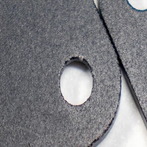
Anodizing Racking Points (Applicable for anodizing process) |
|
Standard | Racking points for anodizing are allowed at locations that do not affect assembly functionality (maximum 4 locations; multiple points within a single hole count as one location). Unless otherwise specified, the locations of the racking points shall be determined by the manufacturer based on experience to achieve the optimal position. |
| Strict | Extremely subtle anodizing racking points are allowed on the product's non-cosmetic surfaces or at locations specified on 2D drawings. Racking/contact marks are not allowed on cosmetic surfaces (default to UV printing surface or laser marking surface). | ||
| Premium | Racking points are only allowed on non-cosmetic surfaces. (The UV printing surface and laser marking surface are deemed cosmetic surfaces by default.) Any racking points in unspecified areas are strictly prohibited. A 2D drawing must be provided to specify acceptable racking point locations. | ||
| Scratches |
|
Standard | Minor scratches within 10mm are allowed on the product (no more than 5 scratches). |
| Strict | Minor scratches within 5mm are allowed on the product (no more than 2 scratches). No scratches or similar defects are allowed on cosmetic surfaces (default to UV printing surface or laser marking surface). | ||
| Premium | No visible scratches or defects are allowed on any cosmetic surfaces. | ||
|
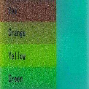
Color Variation (Applicable for anodizing process) |
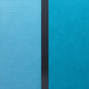
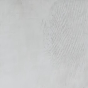
(an example of Color Variation within standard requirements) |
Standard | Slight anodizing color variation among some products is allowed (including products of the same item in the same batch). |
| Strict | No visible color variation is present. (Color variation may still occur between different batches or between different models within the same batch. If you have a request regarding color variation, please leave a remark.) | ||
| Premium | No visible color variation is present. (Color variation may still occur between different batches or between different models within the same batch. If you have a request regarding color variation between different models, please leave a remark.) | ||
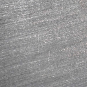
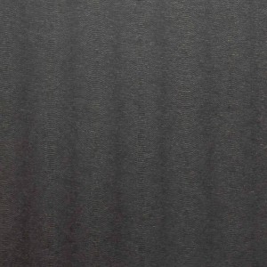
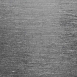
| Tool Marks |
(an example of Tool Marks without beading or anodizing) |
Standard | Minor machining/tool marks that do not affect structural or functional performance are allowed on the surface. Manual polishing is allowed, provided there are no obvious protrusions (when bead blasting treatment is not selected). |
| Strict | With bead blasting and anodizing treatment applied, no machining/tool marks are allowed on the surface. | ||
| Premium | With bead blasting and anodizing treatment applied, no machining/tool marks are allowed on the surface. | ||
| UV Printing |
|
Standard | Slight blurring around the edges of printed patterns or text is allowed; color deviation of patterns caused by the material base color is not regulated; minor positional shifts of the printed pattern are allowed. |
| Strict | Due to the characteristics of the UV printing process, certain imperfections may occur. If such conditions are unacceptable, please consider this limitation carefully. | ||
| Premium | Due to the characteristics of the UV printing process, certain imperfections may occur. If such conditions are unacceptable, please consider this limitation carefully. | ||
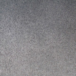
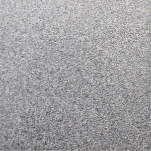
| Surface Roughness |
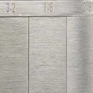
|
Standard | Ra3.2 |
| Strict | Ra1.6 | ||
| Premium | Standard requirement of Ra 1.6, with Ra 0.8 available upon request. |
Notes
Bead Blasting Process
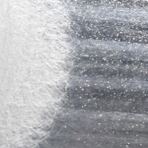
• Deformation Risk for Thin-Walled Parts: Excessively thin workpieces may undergo significant deformation under the impact force of bead blasting. Therefore, if bead blasting is required, it is recommended to increase the wall thickness to above 1.5 mm, or alternatively select a process without sandblasting.
• Risk of Small Part Loss: For small parts (length < 5 mm, weight < 1 g, or lightweight/thin structures), the clamping contact area is limited. During bead blasting and anodizing, high-pressure blasting and stirring of the anodizing bath may cause parts to loosen or fall off, resulting in a relatively high risk of part loss. Therefore, bead blasting and anodizing are not recommended for very small parts.
• Threaded Hole Treatment: Bead blasting media may become trapped in fine threads, potentially affecting the usability of threaded holes smaller than M5. To prevent this, protective rubber plugs will be used, and threaded holes below M5 will not undergo anodizing treatment. Please be aware of this process arrangement; if special anodizing requirements are needed, please inform us in advance.
Anodizing Process
• Differences in Machining Finishes: Parts with the same raw materials but different machining finishes (e.g., wire-cut surface, milled surface, polished surface) can result in color variations after anodizing.
• Differences in Hanging Positions: Parts hung at different heights in the same anodizing tank may exhibit slight color differences after surface treatment.
• Batch Differences: Comparatively obvious color variations may occur after anodizing for parts from different order batches or different orders in the same batches.
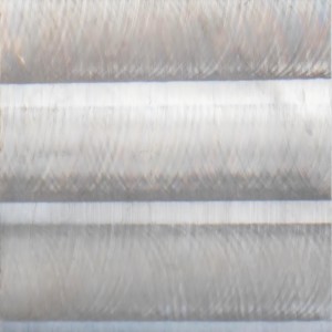
Detailed Views of The Appearance
 |
|
|
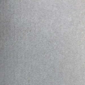
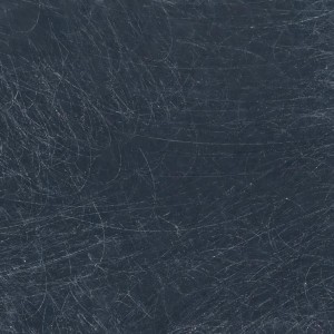
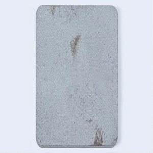
| Anodization Streaks without Beading | Tool Marks without Anodization | Roughness Comparison |
 |
 |
 |
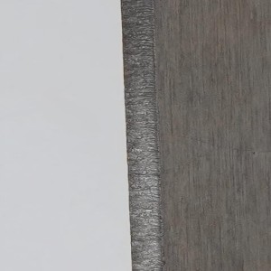
| High-Speed Wire EDM | Medium-Speed Wire EDM | Spark Marks |
 |
|
 |
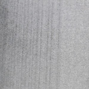
| Scuffs | Scratches | Hand Polished VS Unpolished |
|
 |
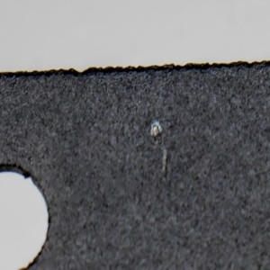 |
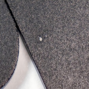
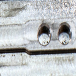
| Anodizing Racking Points | Spot Damage | Impact Marks |
|
|
 |
| UV Printing-Overlapping Colors | Color Variation | Laser Cutting Marks |
 |
 |
 |
| Rust Stain | Stains | Smudge |
 |
 |
 |
| Surface-Treated without Tool Mark1 | Surface-Treated without Tool Mark2 | Brushing |