Sheet Metal Fabrication Guidelines
Last updated on Apr 17, 2026
Dear Customer,
To avoid any unnecessary disputes, we recommend that you carefully read the following sheet metal fabrication guidelines before placing an order.
Please note that our sheet metal orders must be submitted first, and payment will be made after approval. For the complete ordering process, please refer to How to Place A Sheet Metal Order.
1. File Requirements
1.1 Supported Drawing Formats
- 3D (Required): STEP (.step, .stp)
- 2D: PDF, DWG, DXF, JPG, PNG
1.2 2D File Requirements for Laser Marking & Silkscreen (DWG, DXF)
- Upload the marking/silkscreen drawing based on the actual flat shape after bending → DO NOT upload the unbent, unfolded sheet exported from CAD
- Clearly draw part outline and hole positions (if included).
- Text requirements: must use double-line font with a 0.2mm line width(see sample image)
1.3 File Upload Notes
- Compressed packages (.rar, .zip) can be uploaded directly
- Ensure the package contains the required 3D file (.step, .stp)
- Upload locations:
-Silkscreen/Laser Marking files → “Surface Treatment” section
-Thread/Riveting drawings → “Thread or Riveting File” section
1.4 Recommended File Structure
For optimal processing, we recommend uploading a compressed package that includes:
- 3D file (required)
- 2D file
- Silkscreen file
Ensure all files for the same design share the same name
1.5 Upload Quantity and Size Limits
- Maximum 20 drawings per upload
- Maximum 100 MB per file
2. Design Guidelines
2.1 Assembly Guidelines
If parts have an assembly requirement, please include all components in a single 3D file.
This allows our production team to recognize assembly relationships, conduct test fitting, and ensure proper assembly.
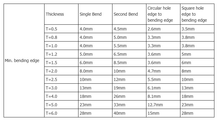
2.2 Bending Design Constraints
- Minimum length of bending edge
- Minimum distance from hole to bending edge
(Please follow platform-specific limits.)
2.3 Hole Spacing Requirements
- Minimum distance between holes: 1 mm
- Distance < 1 mm:
- Considered high risk
- May result in damage by default
2.4 Bending Outer R Corner Radius
| Thickness(mm) | 0.5 | 1 | 1.2 | 1.5 | 2 | 2.5 | 3 | 4 | 5 | 6 |
| Outer R corner radius | 1.2 | 1.8 | 2 | 2.75 | 3.7 | 5 | 6 | 8 | 10 | 12 |
2.5 Minimum Diameter Specification for Sheet Metal Cutting Holes
- Must be at least half of the sheet thickness
- Must be ≥ 1 mm
2.6 Bent U-Shaped Structure (Minimum Center Width)
(The minimum width position as indicated by the red arrow in the attached figure below)
| Thickness(mm) | The minimum width at the center of the bent U-shaped structure(mm) |
| 1 | 12 |
| 2 | 12 |
| 3 | 18 |
| 4 | 20 |
| 5 | 23 |
| 6 | 25 |
3. Production Specifications
3.1 Tolerance Specifications
| General Tolerances | ±0.2mm |
| Cutting Tolerances | ±0.1mm |
| Bending Tolerances | ±0.3mm |
| Bend angle Tolerances | +1.0° |
| Punching Tolerances | ±0.1mm |
| Holes diameters Tolerance | ±0.1mm |
| Thread Tolerance | ±0.1mm |
3.2 Welding
- Since the welding process may cause issues such as thermal deformation, surface irregularities, and color differences, our standard processing services do not include welding by default.
- Should your part require welding, please add a remark during the order submission process.
3.3 Silkscreen Colors
The standard silkscreen colors we support are shown in the image below.
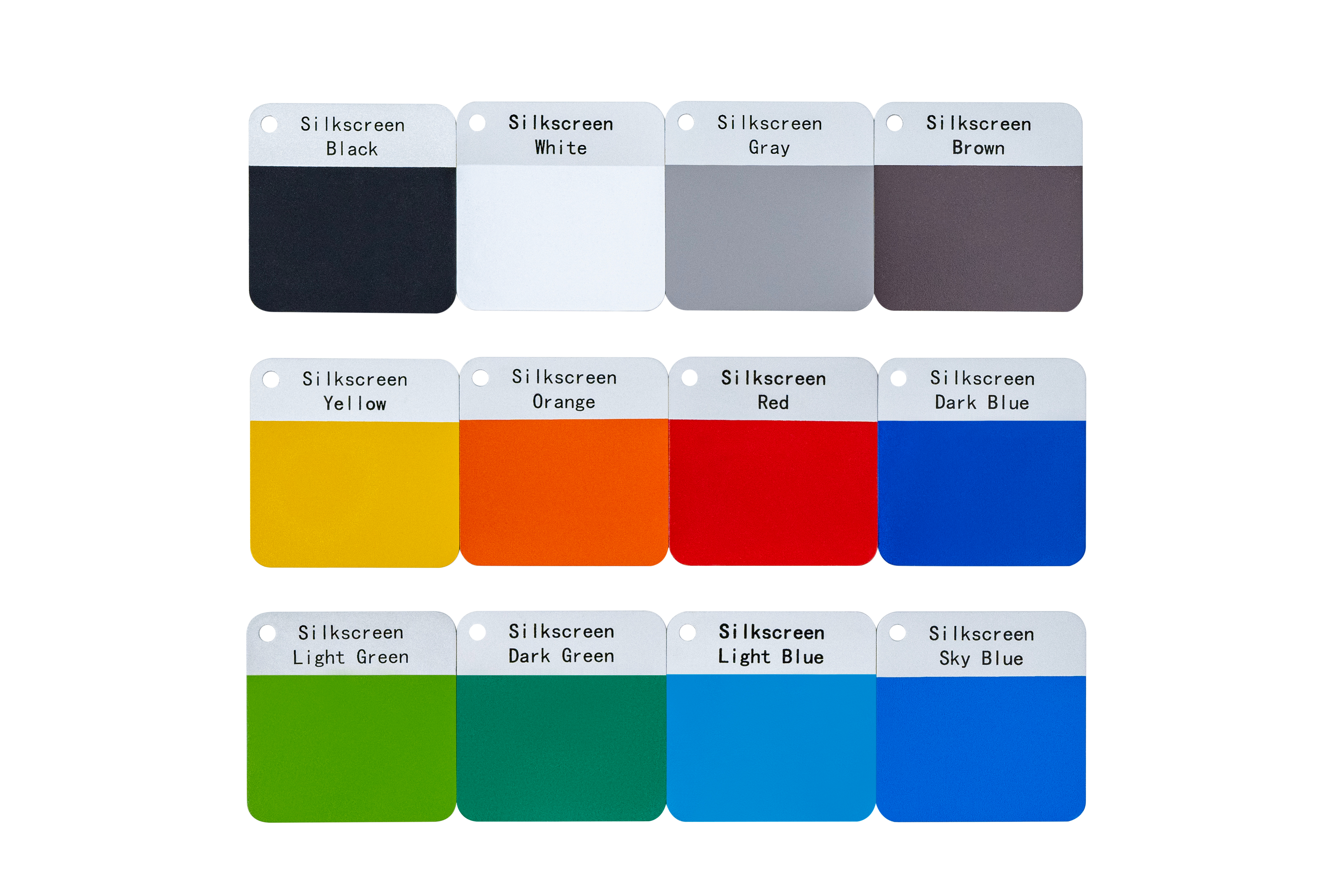
Please note:
Actual results may vary depending on:
- Surface treatment (roughness, glossiness)
- Lighting conditions in the usage environment
3.4 Materials, Surface Treatments & Processes
We offer standardized options for:
- Materials
- Surface treatments
- Machining processes
For details, please refer to: Materials Supported in Sheet Metal Fabrication.
3.5 Custom Parameters for Sub-Components
- Custom machining parameters can be applied to individual parts within an assembly
- If you have specific requirements for a sub-component:
- Specify details in machining options
- Custom part name must match the sub-component name in the design file
4. Feedback & Contact
If you have any comments or suggestions regarding JLCCNC Sheet Metal services, please contact:
support@jlcpcb.com
Our team is committed to providing you with the highest level of service.