Sheet Metal Design Guidelines for Bends, DFM, and Aluminum Parts
18 min
- What Is Sheet Metal Design (Definition & Examples)
- Sheet Metal Design Rules (Quick Reference)
- Key Features in Sheet Metal Part Design
- Sheet Metal Design Calculations (Bend Allowance and K-Factor)
- Practical Sheet Metal Design Tips to Reduce Cost
- Sheet Metal Design for Aluminum
- Common Sheet Metal Design Mistakes to Avoid
- FAQ About Sheet Metal Design
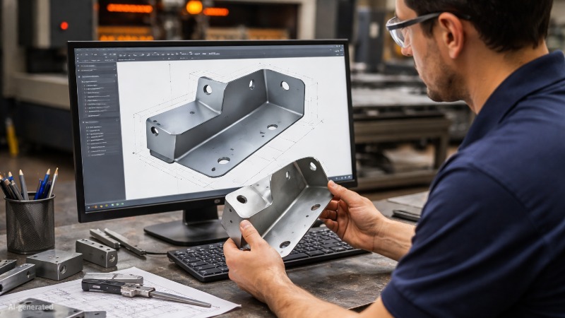
(AI generated) Engineer reviewing CAD model
Many sheet metal parts appear correct in CAD but fail during fabrication because the geometry does not match real tooling and process limits. Common issues include bend radii that are too tight, flanges that are too short, or features placed too close to bend lines.
These design mismatches often lead to part rejection, redesign, or production delays. Fabricators frequently need to modify or reject parts when manufacturing constraints are not considered, increasing costs and extending lead times.
This guide explains how sheet metal design works in real manufacturing. You’ll learn practical design rules, calculations, and DFM (Design for Manufacturability) principles to help you create parts that are easier to produce, more cost-efficient, and reliable in production.
What Is Sheet Metal Design (Definition & Examples)
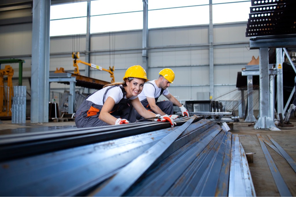
(Freepik) Workers setting down sheet metal
Sheet metal design defines how you create parts from flat metal sheets using processes like cutting, bending, and forming. You control the shape, dimensions, tolerances, and features so the part can be manufactured efficiently.
You’ll see this approach everywhere in modern manufacturing. Automotive enclosures, electronics housings, HVAC panels, machine guards, and aerospace brackets all rely on careful sheet metal part design.
The goal is to design a flat sheet that can be formed into a functional 3D part without unnecessary cost or fabrication issues.
Definition and Scope of Sheet Metal Design
Sheet metal design means planning parts that start as flat sheets and become structural components after forming.
Most industrial sheet metal falls between 0.5 mm and 6 mm thick, depending on the application. Designers choose materials like steel, stainless steel, or sheet metal design for aluminum when weight reduction matters.
Your design must account for several physical realities:
• material thickness
• bend radius
• bend allowance
• manufacturing tolerances
• tooling limits
If you ignore these factors, the part may fail during fabrication or require redesign.
Experienced engineers think about manufacturability before they finish the CAD model. They think about manufacturing before they finish the CAD model.
Why Design for Manufacturability (DFM) Matters
Design for Manufacturability, or DFM, means designing parts that machines can actually produce.
When you follow proven sheet metal design guidelines, several things improve immediately:
• production time drops
• material waste decreases
• fabrication errors disappear
• assembly becomes easier
Manufacturers see real financial impact here. That improvement happens because designers stop creating geometry that machines struggle to produce.
Sheet Metal Design Rules (Quick Reference)
You avoid most fabrication problems by following a few proven sheet metal design guidelines. These rules reflect how metal behaves during cutting and bending. Keep them in mind while modeling your sheet metal part design.
| Design Rule | Recommended Value | Why It Matters |
|---|---|---|
| Minimum bend radius | ≥ 1 × material thickness (varies by alloy, temper, grain direction, and tooling) | Prevents cracking and excessive stress during bending. More formable materials can usually accept tighter bends, while harder alloys often require larger radii. |
| Minimum hole diameter | ≥ material thickness | Ensures holes cut cleanly during laser cutting or punching without distortion. |
| Hole edge to sheet edge distance | ≥ 1.5 × material thickness(increase it when the part is heavily formed or highly loaded) | Maintains material strength around the hole and prevents edge tearing. |
| Hole edge to bend tangent line distance | ≥ 2 × material thickness(increase it when tight tolerances are required) | Avoids deformation of holes when the sheet bends near them. |
| Minimum flange length | ≥ 3 × material thickness(varies by press brake tooling and die width) | Gives the press brake tooling enough clearance to form the bend accurately. |
These guidelines help you create parts that machines can produce consistently. When you follow these guidelines early in the design phase, you reduce fabrication errors, avoid redesigns, and keep production costs under control.
How Fabricators Interpret Sheet Metal Designs in Production
Fabricators do not interpret sheet metal designs exactly as they appear in CAD models. Instead, they evaluate whether each feature can be produced using available machines, tooling, and standard processes such as cutting, bending, and forming.
In practice, manufacturers focus on key factors like bend feasibility, tool clearance, material behavior, and tolerance control. Features that seem acceptable in design—such as tight bend radii, short flanges, or closely spaced holes—may create challenges during production or require adjustments.
Understanding this transition from design intent to manufacturing execution helps bridge the gap between theory and reality. It ensures that parts are not only correctly designed but also practical to fabricate at scale.
Key Features in Sheet Metal Part Design
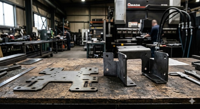
(AI generated) Flat sheet metal blank placed next to the same part after CNC
The sections below cover the structural features that define most sheet metal part design.
Bends, Flanges, and Corners
Bending transforms a flat sheet into a structural component. Modern CNC press brakes can produce highly repeatable bends, but final accuracy still depends on tooling, setup, material variation, and bend sequence.
You’ll design three main bend features.
Bends
A bend changes the direction of the sheet. The inside bend radius typically equals one material thickness, though aluminum sometimes allows tighter radii.
Tighter bends increase stress and can crack brittle materials. Designers typically address this by increasing the bend radius, adjusting the bend direction, or selecting a more formable material.
Flanges
Flanges add stiffness and create mounting surfaces. They also give the part structural rigidity.
Good sheet metal design guidelines suggest a minimum flange length of about three times the sheet thickness. That length gives the press brake tooling enough clearance to form the bend cleanly.
Shorter flanges often cause interference with the punch or die.
Corners
Corners appear where two bends intersect. Designers usually add relief cuts or small radii at these intersections.
Without relief, the material bunches up during bending. That creates deformation or tearing.
Holes, Slots, and Cutouts
Cut features define how the part mounts, connects, or interacts with other components.
Most sheet metal fabrication relies on fiber laser cutting, which now dominates the industry. Design rules keep these features manufacturable.
Holes
Hole diameter should usually equal or exceed the material thickness. Smaller holes can distort during cutting or punching.
You should also keep holes away from edges. A safe rule is 1.5× the sheet thickness for edge distance.
Slots
Slots help with alignment during assembly. Engineers often use them when components require positional adjustment.
Long slots distribute stress better than small holes when parts experience vibration or thermal expansion.
Cutouts
Large cutouts reduce weight and material usage. Designers often place them in enclosures or structural brackets.
Cutouts also help prevent warping by allowing stress relief during bending.
Tabs, Notches, and Hem Features
Small geometric features often determine whether a part assembles easily or becomes a headache during installation.
Tabs
Tabs extend from the sheet and fit into slots or mating parts. They simplify alignment during assembly.
Many fabrication engineers prefer tabs for locating parts before welding or fastening.
Notches
Notches remove material where bends intersect. This prevents overlapping material and improves bend accuracy.
A common notch width equals 1–2× material thickness.
Hems
Hems fold the sheet metal edge back onto itself. They serve two practical purposes.
First, hems remove sharp edges. Second, they strengthen the part’s perimeter.
In sheet metal enclosure design, hems can significantly improve local edge stiffness and remove sharp edges at the same time.
Flat Pattern and Bend Allowance
Every sheet metal part design starts as a flat pattern.
The flat pattern shows the unfolded sheet before bending. Fabrication machines cut this shape from raw material.
During bending, metal stretches slightly along the outside surface and compresses inside the bend. That deformation changes the final dimensions of the part.
Designers account for this behavior using bend allowance and bend deduction.
Bend allowance calculates how much extra material the bend consumes. The value depends on:
material thickness
bend radius
bend angle
material type
Aluminum and mild steel behave differently here. Bend behavior varies by alloy and temper, so aluminum parts often require different bend allowance values than mild steel parts.
Modern CAD software calculates bend allowance automatically, but the designer must supply correct parameters.
When you define those values correctly, the flat pattern matches the final formed geometry. The part bends accurately, holes align, and assembly fits as expected.
This step often determines whether the part works on the first fabrication run or requires costly redesign.
A clean CAD model doesn’t guarantee a manufacturable part. Bend radii, hole spacing, and flat pattern calculations decide whether your design moves straight to production or comes back for revision.
If you want to validate these rules on a real part, an online manufacturability review can help catch bend and tooling issues before production. Upload your file to JLCCNC and get an instant manufacturability review, accurate pricing, and professional sheet metal fabrication starting from just $1 for basic parts.
Sheet Metal Design Calculations (Bend Allowance and K-Factor)
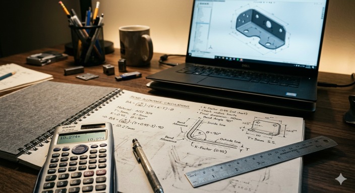
(AI generated) Engineer calculating sheet metal bend allowance and K-factor
What Is Bend Allowance in Sheet Metal Design
Bend allowance measures how much material the bend consumes when forming the part.
When a press brake bends metal, the outer surface stretches while the inner surface compresses. Somewhere inside the material sits a neutral layer that keeps its original length.
Bend allowance calculates the length of that neutral layer inside the bend.
Designers add this length to the flat pattern so the final formed part matches the intended dimensions.
Typical bend allowance depends on:
-material thickness
-bend angle
-bend radius
-material type
Aluminum stretches more than mild steel. Stainless steel behaves differently again. That’s why sheet metal design guidelines require accurate material data.
What Is K-Factor and Why It Matters
The K-factor defines where the neutral axis sits inside the material thickness.
It represents the ratio between the neutral axis location and the total thickness of the sheet.
Typical K-factor values starting range(actual production values should be validated by test bends):
mild steel: 0.30–0.40
aluminum: 0.33–0.50
stainless steel: 0.40–0.50
A lower K-factor means the neutral axis shifts closer to the inside of the bend. A higher value moves it toward the center.
Modern CAD tools like SolidWorks and Autodesk Fusion 360 use K-factor values to automatically generate flat patterns for sheet metal part design.
Still, experienced engineers often calibrate K-factor values based on real shop testing. Even small changes affect final dimensions.
Bend Deduction vs Bend Allowance (Key Differences)
Bend allowance and bend deduction both describe material behavior during bending. They simply approach the problem from different directions.
Bend allowance
Measures the length of the neutral axis inside the bend. Designers add this value when calculating flat patterns.
Bend deduction
Represents the difference between the total flange lengths and the flat pattern length.
In practice:
bend allowance → adds length to the flat pattern
bend deduction → subtracts from flange measurements
Most modern CAD tools handle both calculations automatically. Designers only need to supply correct material thickness, bend radius, and K-factor.
How to Calculate Flat Pattern Length
The flat pattern defines the exact shape the machine cuts before bending.
You calculate it by combining straight flange lengths and bend allowance.
A simplified formula looks like this:
For a simple single-bend part, the flat length is calculated from the straight sections plus the bend allowance. In practice, shops often use calibrated bend tables or bend deduction values because real results depend on tooling and material behavior.
Flat Pattern Length = Sum of flange lengths + Bend Allowance
For example:
two flanges of 100 mm each
one 90° bend
bend allowance of 3 mm
Flat pattern length = 203 mm
Small errors here multiply quickly across multiple bends. Complex parts with several bends can drift several millimeters if the calculations are wrong.
That’s why reliable sheet metal design tips always emphasize accurate bend data.
Why Incorrect Calculations Lead to Fit Issues
Incorrect bend calculations create problems that show up during assembly.
Common issues include:
misaligned mounting holes
incorrect enclosure dimensions
parts that cannot assemble together
Even a 1–2 mm dimensional error can cause serious problems in precision assemblies.
Manufacturing engineers often test bend parameters using sample coupons before full production runs. Once the shop confirms the correct bend allowance and K-factor, those values feed into the production CAD models.
Accurate calculations keep the flat pattern correct and the final sheet metal part design consistent.
Practical Sheet Metal Design Tips to Reduce Cost
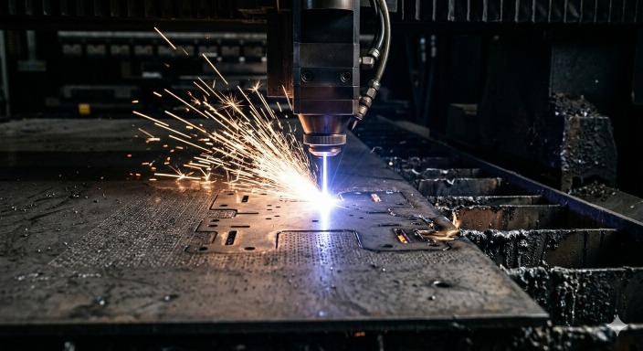
(AI generated) Industrial laser cutting machine creating complex sheet metal features.
Good sheet metal design tips often come from practical shop experience. Fabrication engineers see the same design mistakes every week.
Fixing those mistakes early improves part strength, reduces production cost, and prevents manufacturing delays.
These practices consistently produce better sheet metal part design results.
Reduce Bend Count
Every bend adds forming time, handling, and inspection. Parts with fewer bends move through the press brake faster, require fewer repositioning steps, and usually show less tolerance buildup.
When possible, combine functions into fewer bends or simplify the overall geometry. Reducing bend count is often one of the fastest ways to lower sheet metal fabrication cost without changing the part’s purpose.
Consistent bend direction can also reduce handling time because the operator does not need to flip the part as often during forming.
Standardize Bend Radii
Using the same bend radius across a part or assembly helps reduce setup time and tooling changes. It also makes bending more predictable, which improves consistency during production.
If every bend requires a different tool or setup, the part becomes slower and more expensive to manufacture. Standardized radii are one of the simplest ways to improve efficiency in sheet metal production.
Avoid Tiny or Complex Features
Very small holes, narrow slots, tight internal corners, and irregular cutouts often slow down fabrication and increase the risk of defects. These features may require slower cutting speeds, additional finishing, or tighter process control.
As a general rule, keep feature sizes practical for the material thickness and avoid unnecessary geometric detail. Simpler cut geometry is usually faster to produce and easier to keep within tolerance.
Reduce Secondary Operations
Secondary operations such as tapping, welding, grinding, and machining add time, labor, and cost. A part that can be cut and bent with minimal extra processing is usually more economical to produce.
Good design can often remove these steps. Tabs and slots may reduce the need for welding, self-clinching fasteners can replace tapped holes, and hems can improve edge safety without manual deburring.
Sheet Metal Design for Aluminum
Aluminum looks easy on paper. It cuts clean, forms fast, and keeps weight down. The problems show up later. Bends don’t land where you expect. Edges start cracking. Parts lose stiffness faster than planned. That’s why sheet metal design for aluminum needs tighter control from the start, not after the first failed batch.
Aluminum Material Properties in Fabrication
Aluminum doesn’t behave like steel under load. It’s softer, more ductile in some grades, and less forgiving in others.
In sheet metal part design, that means parts form easily, but they also lose shape if support isn’t built in. Aluminum parts may need additional attention to stiffness and cyclic loading, especially in thin sections or highly stressed applications.
These aren’t edge cases. They directly shape how sheet metal design guidelines are applied when aluminum is involved.
Bend Radius and Springback Considerations
This is where most designs break.
Aluminum doesn’t tolerate tight bends the way mild steel does. Push the radius too low, and micro-cracks start forming along the bend line. At the same time, springback shifts your final angle.
Aluminum usually shows more springback than mild steel, so the final angle often opens slightly after release. Shops typically compensate by overbending or validating the angle with test bends. That gap forces rework if it’s not planned for. Most teams solve this by increasing bend radius and adjusting tooling angles early instead of correcting it later.
Thickness Selection for Aluminum Parts
Thickness decisions don’t stay isolated. They affect everything downstream.
Go thinner, and the part becomes easier to form but less stable. Go thicker, and you improve rigidity but increase forming force and springback. That tradeoff shows up fast in production.
Most sheet metal design tips follow a simple logic. Size thickness based on load first, then check if the part can still be bent without cracking or distortion.
Comparing Aluminum vs Steel in Design
This isn’t just a material choice. It’s a cost and performance decision.
Aluminum has about one-third the density of steel, so an equal-volume part is roughly two-thirds lighter, which makes it useful for enclosures and panels. But it gives up strength and wear resistance in return. Steel holds shape better under load and handles tighter tolerances in structural parts.
In sheet metal part design, aluminum wins on weight and formability. Steel wins on strength and durability.
Typical Bend Radius for 5052 vs 6061
Grade selection changes everything at the bend.
As a general rule, 5052-H32 is more bendable than 6061-T6. Many shops can bend 5052 at around 1t, while 6061-T6 often needs a larger inside radius such as 2t to 3t especially in perpendicular bend direction to rolling grain, depending on bend direction and finish requirements.
In practice, 5052 is usually preferred for parts with tighter bends, while 6061 is chosen more often when strength matters more than bendability.
This is why sheet metal design for aluminum isn’t just about thickness. Alloy choice controls how far you can push the geometry.
Springback Compensation Strategies
You don’t eliminate springback. You work around it.
The common fix is overbending. Operators push past the target angle so the part relaxes into position. That works, but it takes calibration. Small errors here can throw off the entire batch.
More controlled setups use simulation or test bends to predict behavior before full production. That reduces trial runs and keeps angles within tolerance.
In practice, this is where good sheet metal design guidelines pay off. Plan for springback early, or deal with it on every part later.
Common Sheet Metal Design Mistakes to Avoid
| Sheet Metal Design Mistake | What Happens in Production | Simple Fix |
|---|---|---|
| Ignoring bend radius and K-factor | Cracks appear on bend lines, flat patterns produce parts that come out short or misaligned | Use material-specific bend radius values and validated K-factor charts |
| Placing holes too close to bends | Holes distort during forming, become oval, shift position, or weaken the surrounding edge | Keep hole distance ≥ 1.5–2× material thickness from bend lines |
| Overly tight tolerances | Production slows down, inspection increases, fabrication cost rises significantly | Apply tight tolerances only where fit or assembly requires them |
| Poor material selection | Hard materials crack or slow bending, soft materials lose strength in load-bearing parts | Match material to function (e.g., aluminum for lightweight panels, steel for structural parts) |
You’ve seen the rules. Bend radius, hole spacing, flat patterns, K-factor. These details decide whether your sheet metal part design works in the real world or fails during fabrication.
Now test your design against real manufacturing.
Upload your CAD file to JLCCNC and get instant pricing, a manufacturability review, and professional fabrication for steel, stainless steel, and sheet metal design for aluminum parts. You’ll see quickly whether your design follows proven sheet metal design guidelines and how to improve it before production begins.
FAQ About Sheet Metal Design
Q: What are the basic rules for sheet metal design?
Keep geometry simple, avoid unnecessary bends, and design for manufacturability rather than appearance.
Q: What is the minimum bend radius?
Typically around 1× material thickness, but it increases for harder materials to prevent cracking.
Q: How do you calculate bend allowance?
It’s calculated using thickness, bend angle, inside radius, and K-factor to predict flat pattern length.
Q: What materials are best for sheet metal design?
Steel for strength and structure, aluminum for lightweight applications, depending on load and cost needs.
Q: What is a good starting bend radius for sheet metal?
A good starting point is an inside bend radius equal to the material thickness, or about 1t. However, the correct radius depends on the material, temper, bend direction, and tooling, so harder alloys such as 6061-T6 aluminum often need a larger radius.
Q: What is the K-factor in sheet metal?
It defines material stretching during bending and is used to calculate accurate bend allowance in flat patterns.
Keep Learning
Counterbore Holes: Symbols, Callouts, Dimensions & Applications
Key Takeaways A counterbore provides extra space above a hole so the fastener head does not project above the part surface. Socket head cap screws are commonly installed in counterbore holes because the recess matches the shape of the screw head. Three dimensions define the feature: the hole size, the recess diameter, and the recess depth. The hole and the recess are machined on the same centerline to maintain proper alignment between the hole and the recessed seating surface. In most applications, th......
Differences Between Tolerance and Allowance
Key Takeaways Tolerance controls the allowable variation of a single dimension, while allowance is the intentional difference between two mating parts that determines the type of fit. Tolerance and allowance are closely related but describe different aspects of dimensional control. Tolerance defines the acceptable variation of a single dimension, while allowance defines the intentional difference between mating parts to achieve a required fit. Confuse them and you end up with parts that either won't a......
Types of Holes in Engineering: Design, Symbols, and Manufacturing Guide
Types of holes in engineering - illustration (Erye rubber & plastic parts) Key Takeaways Engineering holes are used to support fastening, alignment, bearing installation, fluid flow, and other functional requirements. The main types of holes include through holes, blind holes, threaded holes, counterbore holes, countersink holes , spotface holes, screw clearance holes, reamed holes, and dowel holes. Hole geometry determines the required machining process. Some holes only require CNC drilling , while o......
True Position in GD&T: Symbol, Formula, Tolerance, and Manufacturing Applications
Key Takeaways About True Position True position defines the allowable variation in a feature's location from its basic dimensions. The control applies to holes, slots, pins, threaded features, and datum features. A circular tolerance zone controls features in 2D, while a cylindrical zone controls feature axes in 3D. Datum references establish the coordinate system used for manufacturing and inspection. Maximum Material Condition (MMC) adds bonus tolerance as the feature departs from its maximum materi......
Tolerance Stack-Up: Analysis, Examples, and How It Affects Manufacturing and Assembly
Key Takeaways About Tolerance Stack-Up Tolerance stack-up determines the dimensional variation that accumulates across multiple features and assembled parts. The stack-up study allows engineers to identify gaps, interference issues, alignment shifts, and fit conditions before production starts. Small dimensional variations from several parts can combine and create larger assembly issues. Usually, worst-case analysis evaluates the maximum possible variation by combining all tolerance limits. Statistica......
How to Read Engineering Drawings: Symbols, Dimensions, and Practical Interpretation
Key Takeaways About Engineering Drawings Engineering drawings communicate product requirements throughout manufacturing, inspection, assembly, and quality control. They communicate information that may not be fully defined in a CAD model, such as allowable variation, surface requirements, and inspection points. A drawing review starts with understanding the part reference system. The machinist checks which surfaces are used as datums, how features relate to each other, and which areas need access duri......