Are There Any Design Limitations or Restrictions for CNC Machining
12 min
- Limitations Overview
- Tool Access
- Minimum Feature Size and Internal Corners
- Wall Thickness
- Part Size Limits
- Material Selection
- Threaded Features
- Tolerances and Cost
- Undercuts and Overhangs
- Feature, Risk, and DFM Action
- A Common Design Mistake Worth Flagging
- FAQ
- Not Sure If Your Design Is Machinable As Drawn?
Quick Answer: CNC design is limited mainly by tool access, cutter radius, part rigidity, workholding, machine travel, material behavior, and tolerance requirements. Review those constraints before finalizing CAD, especially for deep pockets, thin walls, internal corners, undercuts, small threads, and critical fits.
A design that looks completely reasonable in CAD can turn out to be genuinely difficult — or impossible — to machine as drawn. Not because the geometry is wrong in any absolute sense, but because CNC machining removes material with a rotating tool that has physical limits: it can only reach where it has a clear path, it can only cut a corner as sharp as its own radius, and it can't hold a wall so thin that cutting forces flex it out of tolerance. Understanding those physical constraints before finalizing a design is what separates a part that machines cleanly on the first try from one that bounces back with a redesign request.

Precision CNC Machining Service
Professional manufacturing, fast turnaround, and quality assurance.
Limitations Overview
The table below is a quick reference — each row is covered in more depth further down. Every figure here is a starting point for a design review, not a guarantee: actual results depend on the specific material, wall height, tool overhang, workholding setup, machine rigidity, and inspection requirements involved.
| Constraint | Typical starting guideline | What changes it |
|---|---|---|
| Tool access / pocket depth | ~3–4× tool diameter before deflection and chip evacuation become a problem | Tool length, tool diameter, material hardness, chip evacuation method |
| Internal corner radius | 0.5–3mm, matching standard end mill sizes | Feature depth, tool selection, whether EDM is used instead |
| Wall thickness (metal) | ~0.8mm minimum | Wall height, support/ribbing, material stiffness, fixturing |
| Wall thickness (plastic) | ~1.5mm minimum | Same as above — plastics flex more readily under cutting force |
| Part size (single setup) | Bounded by the shop's actual machine work envelope | The specific machine used — always confirm with a quote, not a general figure |
| Thread minimum diameter | Small threads become a tapping-reliability risk below a few mm | Thread pitch, material, hole depth, tapping method |
| Standard tolerance | ±0.05–0.1mm typical for commercial work | Material, feature type, inspection method |
| Undercuts | Not reachable in a single 3-axis setup | Requires a second setup or 4-/5-axis access — see the section below |
Tool Access
CNC cutting tools remove material by approaching from outside the part — they need a clear path to every feature that requires machining. Deep pockets, internal features on multiple sides, and geometry that would require the tool to somehow reach around a corner all run into this constraint directly. Overhangs and hard-to-reach areas often require specialized tooling, a different tool orientation, or an entirely separate setup — each of which adds cost and complexity. As a starting guideline, a standard end mill can reach a depth of roughly 3–4 times its diameter before deflection and chip evacuation become real problems; the exact number shifts with tool material, workpiece hardness, and how well chips clear the cut. Deeper features typically need a longer, more specialized (and less rigid) tool, or a redesign that breaks the feature into a more accessible shape.
Minimum Feature Size and Internal Corners
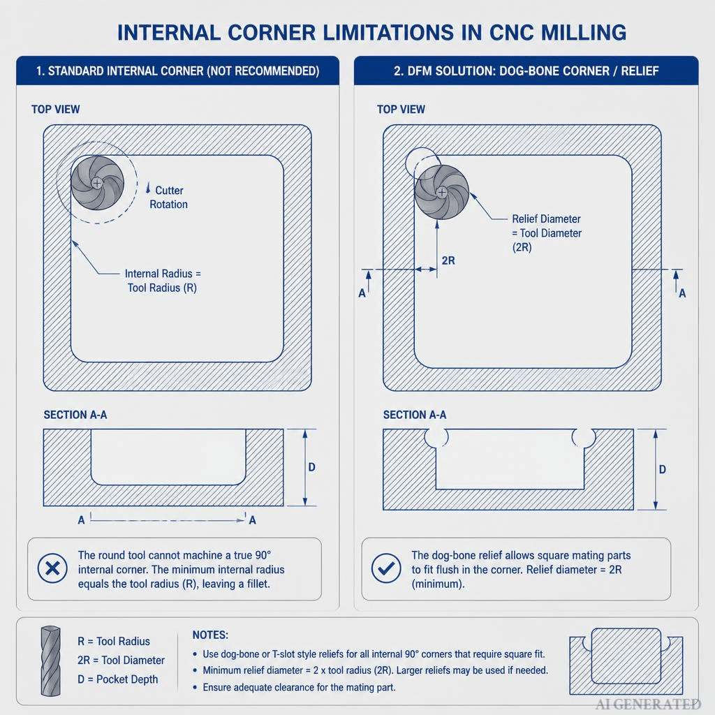
A milling tool is round, which means it can never cut a perfectly sharp internal corner — the corner will always have a radius matching (at minimum) the tool used to cut it. A design that calls for a genuinely sharp 90° internal corner either needs a secondary process (like EDM, which can produce true sharp corners since it doesn't rely on a physical rotating tool) or needs the corner radius adjusted to match what a standard end mill can actually produce. As a starting reference, that's commonly in the 0.5mm–3mm range, but the workable number depends on feature depth and which tool the job actually calls for. Specifying a corner radius that matches standard tooling avoids an unnecessary secondary operation.
Wall Thickness
Thin walls flex under cutting forces, and that flex translates directly into dimensional inaccuracy — a wall machined to spec while the material is briefly deflected under the tool can spring back to a slightly different final dimension once cutting forces are removed. As a starting reference point, metal parts typically need a minimum wall thickness around 0.8mm, while plastic parts generally need more margin — around 1.5mm — since plastics flex more readily under the same cutting forces. Both figures depend heavily on the wall's height, how well it's supported, and the material's specific stiffness — they're a design-review starting point, not a hard cutoff. Walls thinner than these guidelines are still sometimes achievable, but usually need extra fixturing support during machining, slower cutting parameters, or a redesign that adds ribbing for rigidity.
Part Size Limits
Beyond individual features, the overall size of the part is its own constraint — a design has to fit within what a given machine's work envelope can actually hold and reach. Work envelopes vary considerably between machines and shops, so there's no single number that applies universally; a typical mid-size CNC milling setup in the industry often falls somewhere in the range of roughly a meter in each dimension, but this varies by equipment and isn't a specific commitment from any one shop. Anything that might be near the limit needs to be checked against the actual machine that will run the job — splitting a design into multiple machined sections and joining them afterward, or moving to larger-format equipment, are both real options once that limit is confirmed. On the small end, very small parts run into the opposite problem — there's often a practical minimum size below which fixturing the part securely enough for accurate cutting becomes difficult. Checking a design against the intended shop's actual work envelope before finalizing dimensions — through a quote or engineering review rather than a general figure — avoids finding out about this limit after the fact.
Material Selection
Different materials machine differently, and that difference directly affects what's practically achievable in a design. Softer metals like aluminum machine quickly and tolerate more aggressive cutting parameters; harder materials like stainless steel or titanium demand slower speeds, more tool wear, and — for very hard or hardened materials — sometimes rule out conventional machining in favor of EDM instead. A design with tight tolerances or fine features specified for a hard-to-machine material carries more cost and risk than the same geometry in an easier material, and that tradeoff is worth weighing during material selection, not treated as a fixed constraint to work around after the fact.
Threaded Features
CNC machining can cut threads directly into a part rather than requiring a separate insert, which simplifies both design and assembly compared to some other processes. That capability has its own lower limit, though: as thread diameter gets smaller, the thread pitch gets fine enough that tapping reliably — without breaking a tap inside the part — becomes a real risk. Where exactly that risk becomes impractical depends on the specific thread spec, the material being tapped, hole depth, and the tapping method used, so it's worth confirming with an engineering review rather than treating any single diameter as a hard cutoff. Below whatever that practical point turns out to be for a given job, a design may need to move to a larger fastener size or a different joining method entirely. Deep threaded holes carry a related tool-access concern — a tap, like an end mill, has a practical depth limit before chip evacuation and tap breakage become a problem.
Tolerances and Cost
CNC machining can achieve genuinely tight tolerances and fine surface finishes, but the tighter the requirement, the more it costs — in machine time, tooling, and often secondary finishing operations. Standard commercial tolerances typically run around ±0.05–0.1mm. Tighter precision work — commonly cited in the industry in the ±0.01–0.025mm range — is achievable on suitable equipment, but generally requires more careful process control, more inspection, and correspondingly more cost; confirm this specific range against your shop's actual equipment before quoting it as a guarantee. Specifying tight tolerances only where a part's actual function requires them — rather than defaulting to the tightest tolerance available "to be safe" — keeps cost proportional to what the part genuinely needs. Our CNC machining tolerances guide covers this tolerance range and what drives the cost difference in more depth.
Undercuts and Overhangs
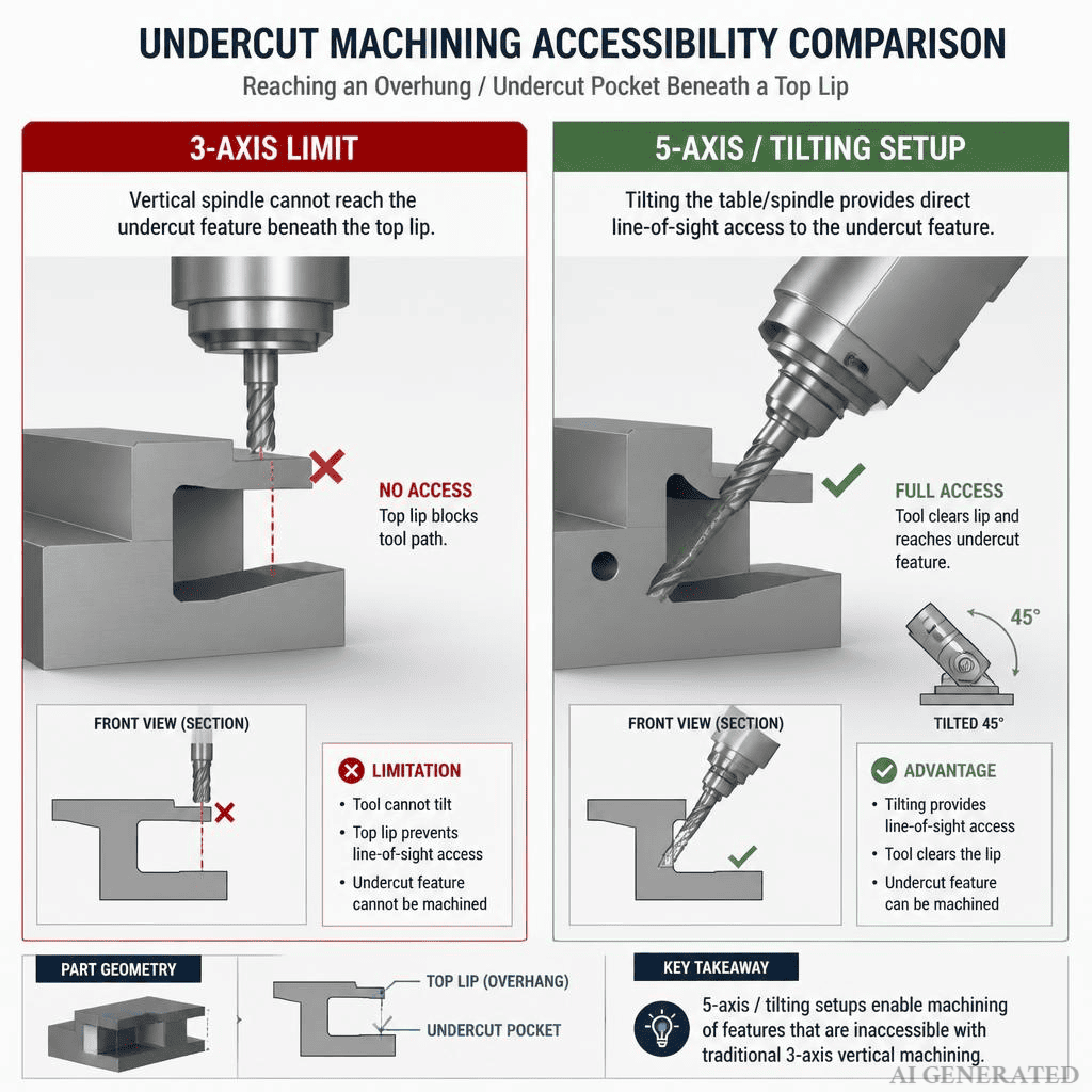
Standard 3-axis CNC machining cuts from a single direction per setup, which means undercuts — features that overhang or curve back beneath an accessible surface — can't always be reached in one pass. Addressing an undercut typically means an additional setup (repositioning the part and re-referencing it, which adds cost and introduces a small risk of alignment error between setups) or moving to 4- or 5-axis machining, which can reposition the tool or workpiece to reach angles a 3-axis setup physically can't.
It's worth being direct here: extra axes don't automatically solve every undercut. Whether a 4- or 5-axis setup can actually reach a given undercut still depends on toolpath access, potential tool/fixture interference, how the part can realistically be held during the cut, and whether the added machine time is worth it compared to a design change. Our 5-axis CNC milling guide covers when that added capability is actually worth the cost versus redesigning around the undercut instead.
Feature, Risk, and DFM Action
Putting the sections above into a single decision reference:
| Feature | Main risk | DFM action |
|---|---|---|
| Deep pocket | Tool deflection, poor chip evacuation, long cycle time | Reduce depth-to-diameter ratio, or split into a more accessible multi-stage structure |
| Thin wall | Flex under cutting force, dimensional drift after machining | Increase thickness, add ribbing, or plan for extra fixturing support |
| Sharp internal corner | Physically impossible with a standard rotating tool | Add a fillet matching a standard end mill radius, or specify EDM for a true sharp corner |
| Undercut | Tool access — not reachable from a single direction | Evaluate a specialized tool, a second setup, 5-axis machining, or a redesign that removes the undercut |
| Very small thread | Tap breakage, unreliable pitch at small diameters | Confirm feasibility for the specific spec and material, or move to a larger fastener/different joining method |
| Tight tolerance on a non-critical feature | Unnecessary machine time, inspection, and cost | Reserve tight tolerances for features that actually require them functionally |
A Common Design Mistake Worth Flagging
Designing a part the way it would be designed for 3D printing or casting — sharp internal corners, thin unsupported walls, deep enclosed cavities — and then expecting it to translate cleanly to CNC machining is one of the most common sources of redesign requests. Those other processes don't share CNC machining's physical constraint of a rotating tool needing clear access and leaving a rounded corner behind; a design genuinely optimized for one process often needs real adjustment, not just a material swap, to machine cleanly on the other.
FAQ
Can CNC machining produce a perfectly sharp internal corner? Not with conventional milling — a rotating tool always leaves a radius matching its own geometry at minimum, commonly cited around 0.5–3mm depending on the tool and feature. A truly sharp internal corner needs a different process like EDM, or the design needs to accept a matching fillet radius instead.
What's the minimum wall thickness CNC machining can hold reliably? It depends heavily on material and geometry, but roughly 0.8mm for metals and around 1.5mm for plastics is a reasonable starting reference for a design review — thinner walls are sometimes achievable with extra support during machining, but at added cost and risk of dimensional drift.
Is there a maximum part size for CNC machining? Yes, every machine has a physical work envelope, but the number varies significantly by shop and equipment — there's no single industry-wide figure worth quoting as a guarantee. Parts near the limit typically need to be checked against the specific machine that will run the job; oversized designs can be split into sections and joined after machining, or sent to a shop with larger equipment.
Is there a minimum size for machined threads? It depends on the thread spec, material, hole depth, and tapping method rather than a single fixed diameter. As threads get smaller, tapping reliably — without breaking a tap inside the part — becomes a real risk, so very small threaded features are worth confirming with an engineering review; they sometimes need a larger fastener size or an alternative joining method instead.
Why does tighter tolerance cost more in CNC machining? Tighter tolerances demand slower, more carefully controlled cutting, more frequent inspection, and sometimes secondary finishing operations to hold the specified accuracy — all of which add machine time and process overhead compared to standard commercial tolerances.
Can CNC machining handle any undercut geometry? Not automatically, and not always in a single setup. Standard 3-axis machining typically needs an additional setup for undercuts, and even 4- or 5-axis equipment — which can reposition the tool or part to reach more angles — still depends on toolpath access, interference, and workholding for a given feature. Some undercuts are more practically solved with a design change than with added machine complexity.
Not Sure If Your Design Is Machinable As Drawn?
A part that looks fine in CAD can still run into real constraints once it hits the machine — tool access, wall thickness, corner radii, tolerance cost. Our engineering team reviews your drawing before quoting and flags any features that may need adjustment, so you're not finding out about a redesign after the fact.
- Engineering Review: Manufacturability feedback with every quote
- Multi-Axis Capability: 3-, 4-, and 5-axis CNC milling for complex geometry and undercuts
- Fast Quotes: Upload your 3D CAD files (.STEP / .IGES) for a rapid review and quote
Popular Articles
• Are There Any Design Limitations or Restrictions for CNC Machining
• From CAD to CNC The Importance of Accurate 3D Modeling in Manufacturing
• Understanding CNC Machine Tolerances and Their Impact on Part Accuracy
• How to Learn CNC Programming: A Step-by-Step Guide for Beginners
• G and M code: a beginner's guide to CNC programming language
Keep Learning
Are There Any Design Limitations or Restrictions for CNC Machining
Quick Answer: CNC design is limited mainly by tool access, cutter radius, part rigidity, workholding, machine travel, material behavior, and tolerance requirements. Review those constraints before finalizing CAD, especially for deep pockets, thin walls, internal corners, undercuts, small threads, and critical fits. A design that looks completely reasonable in CAD can turn out to be genuinely difficult — or impossible — to machine as drawn. Not because the geometry is wrong in any absolute sense, but b......
GD&T in CNC Machining: Everything You Need to Know.
Why Does GD&T Matter in CNC Manufacturing? (autodesk) What is GD and T? Ask five machinists to interpret a drawing without it and you might end up with five completely different parts. That's because traditional linear dimensions and notes can only go so far, leaving plenty of room for misinterpretation. This is where GD&T (Geometric Dimensioning and Tolerancing), the universal language of engineers, is used to define how a part should truly function and fit. At its core, GD&T is a symbolic system tha......
What Is CNC Programming? A Complete Guide
What Is CNC Programming? A Complete Guide A finished CAD model doesn't cut anything by itself. Between a 3D design sitting on a screen and an actual part coming off a machine, there's a translation step that turns geometry into motion — where the tool goes, how fast it moves, when it changes, when coolant kicks on. That translation is CNC programming, and it's easy to take for granted until something in it goes wrong: a program that runs a toolpath through a clamp, a feed rate that's fine on paper but......
From CAD to CNC The Importance of Accurate 3D Modeling in Manufacturing
In modern manufacturing, the process from CAD design to CNC machining is an indispensable part of producing high-quality parts and products, and 3D modelling, as a core part of this process, has a direct impact on the accuracy, functionality and appearance of the final product. In this article, we will discuss the CAD to CNC process, analyse the importance of accurate 3D modelling, and share how to optimise the modelling process to improve manufacturing efficiency and product quality. I. CAD design: l......
What Is Stepover in CNC Machining? Meaning, Surface Finish, and Toolpath Strategy
Stepover in CNC machining refers to the lateral distance a cutting tool moves between successive passes. It is a key parameter in CNC toolpaths that directly affects surface finish, machining time, and tool wear. Understanding what stepover in CNC means is essential for optimizing both roughing and finishing operations in milling processes. What Stepover Means in CNC Toolpaths? CAM toolpath illustrating stepover in CNC machining. (Source: chrisandjimcim.com) Efficient milling requires long-term precis......
From STP File to Finished Part How Online CNC Machining Brings Your CAD Model to Life
Driven by intelligent manufacturing and industrial internet, CNC machining is innovating from traditional mode to digitalization and visualization. As the “international language” for product data exchange, STP file (STEP/STP format) has become the core bridge connecting design and manufacturing due to its high compatibility and integrity. In this article, we will explain how to realize the whole process management from STP files to finished parts through online visualization technology, covering key ......