Introduction of STL/STP File Formats and How to Obtain STP Files
Last updated on Sep 08, 2026
1. Overview
1.1 STL File
STL stands for Stereolithography and is one of the most commonly used and widely supported file formats in the field of 3D printing. It was created by 3D Systems in 1987 for its stereolithography 3D printing technology. Nearly all 3D modeling software and 3D printer slicing software support the STL format, making it a kind of "universal language" in the industry.
Simply put, an STL file describes the surface geometry of a 3D model using a very straightforward approach. It does not contain information such as color, texture, material, or hierarchical structure. Its core principle is to approximate the surface of a complex 3D model using a large number of small triangular facets.
1.2 STP (STEP) File
STP, also known as STEP, is part of the ISO 10303 standard, which defines standards for the representation and exchange of product data. As its name suggests, STEP is designed to enable accurate and complete product data exchange between different CAD systems.
Common CAD software that supports STEP files includes:
- SolidWorks
- Autodesk Fusion 360
- Autodesk Inventor
- PTC Creo
- Siemens NX
- CATIA
- FreeCAD
The file extension is typically .stp or .step.
Unlike STL files, which approximate surfaces using triangular facets, STP files use mathematically defined geometric entities—such as lines, arcs, spline curves, and surfaces—to define the model's boundary representation. This allows the model to represent the original design intent more accurately.
1.3 Core Principle of STP Files: Boundary Representation
STP files use Boundary Representation (B-Rep) to define a 3D model. The model is represented by its geometric surfaces and the boundaries that define how these surfaces connect to one another.
2. Recommended Usage
Based on the principles of STL and STP files, STL models are mesh models composed of approximated triangular facets and therefore cannot fully represent the original design data. In contrast, STP files preserve more accurate geometric information and are better suited to high-precision machining requirements.
Therefore, the appropriate file format should be selected according to the manufacturing process.
Both STL and STP files can currently be used for 3D printing. However, CNC machining generally provides higher dimensional accuracy than 3D printing. Since STL files use an approximated mesh representation of the model surface, they are not well suited for high-precision CNC machining.
Therefore, STP files are recommended as the basis for CNC machining.
3. How to Obtain an STP File
If you need an STP file, you can use one of the following methods:
Method 1: Export the Original Design File
If you have the original CAD design file, you can directly export it to STEP or STP format using your CAD software.
The general procedure is:
Save As → File Type → Select STP/STEP → Confirm
We recommend using the **AP203** version when exporting the STP file.
Method 2: Convert a Mesh Model into a Solid
If you do not have the original CAD design file, you can use the mesh-to-solid conversion function available in your CAD software. The specific procedure varies depending on the software. Please note that this method is mainly suitable for simple models, such as cubes or cylinders. When converting complex models, defective or invalid faces may be generated.
Therefore, after conversion, carefully inspect the final model to ensure that:
- There are no defective or missing faces.
- The model forms a complete, watertight solid.
- The geometry is consistent with the original STL model.
Once the model has been successfully converted into a solid, export it as an STP file.
Method 3: Rebuild the Model Manually
The mesh-to-solid conversion method described above is mainly suitable for simple, geometrically regular parts.
For parts with numerous or complex features, the conversion result may not be satisfactory. In such cases, it is recommended to manually rebuild the model and then export the reconstructed model as an STP file.
Important Note
STL and STP are two different file formats. Simply changing the file extension from .stl to .stp is invalid.
4. Additional Information on Surface Defects
As discussed above, STL and STP files use fundamentally different methods to represent 3D models. This difference can also lead to surface defects when an STL file is converted back into a solid model.
Differences Between STL and STP Models
As shown in the figure below:
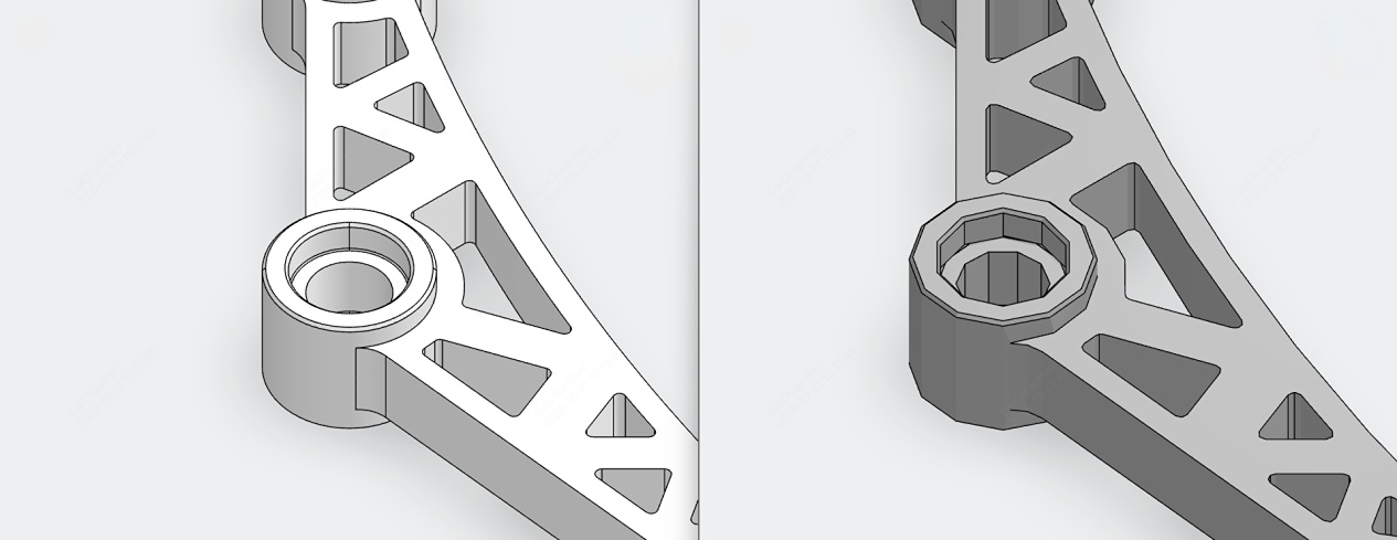
STP and STL model comparison
The STL model (right) shows obvious distortion on curved surfaces. This is because STL represents the model surface using flat triangular facets. Curved surfaces are therefore approximated by a series of small straight edges.
In contrast, STP files(left) use mathematically defined geometric entities and can preserve curved surfaces and other geometric details much more accurately.
Based on the characteristics of STL files, models containing a large number of planar surfaces can generally be represented relatively well. However, when a model contains curved or spline-based surface features, these curves are approximated by many small straight edges. This may result in visible geometric distortion.
Therefore, when converting an STL file back into a solid model, the model features should be inspected first. If the model contains relatively few curved surface features, the STL file may provide a reasonably good representation of the original geometry, and STL-based reconstruction may be suitable.
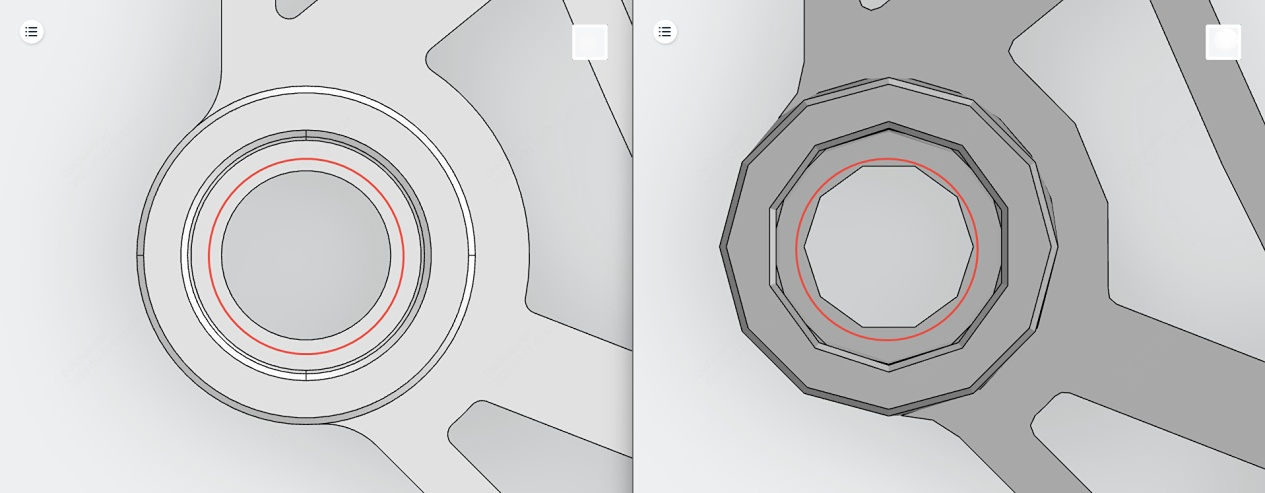
STL curved surface distortion
For relatively regular geometric features, the original design dimensions may sometimes be inferred based on engineering experience. However, this approach is not recommended for spline-based curves. For such features, it is recommended to use CAD software to perform automatic curve or surface fitting.
The fitted geometry should then be evaluated according to the intended application:
- For areas without strict accuracy requirements, the fitted geometry may be used directly.
- For areas with specific accuracy requirements, additional processing may be required.
- For example, special attention should be paid to precision-critical features such as cam surfaces.
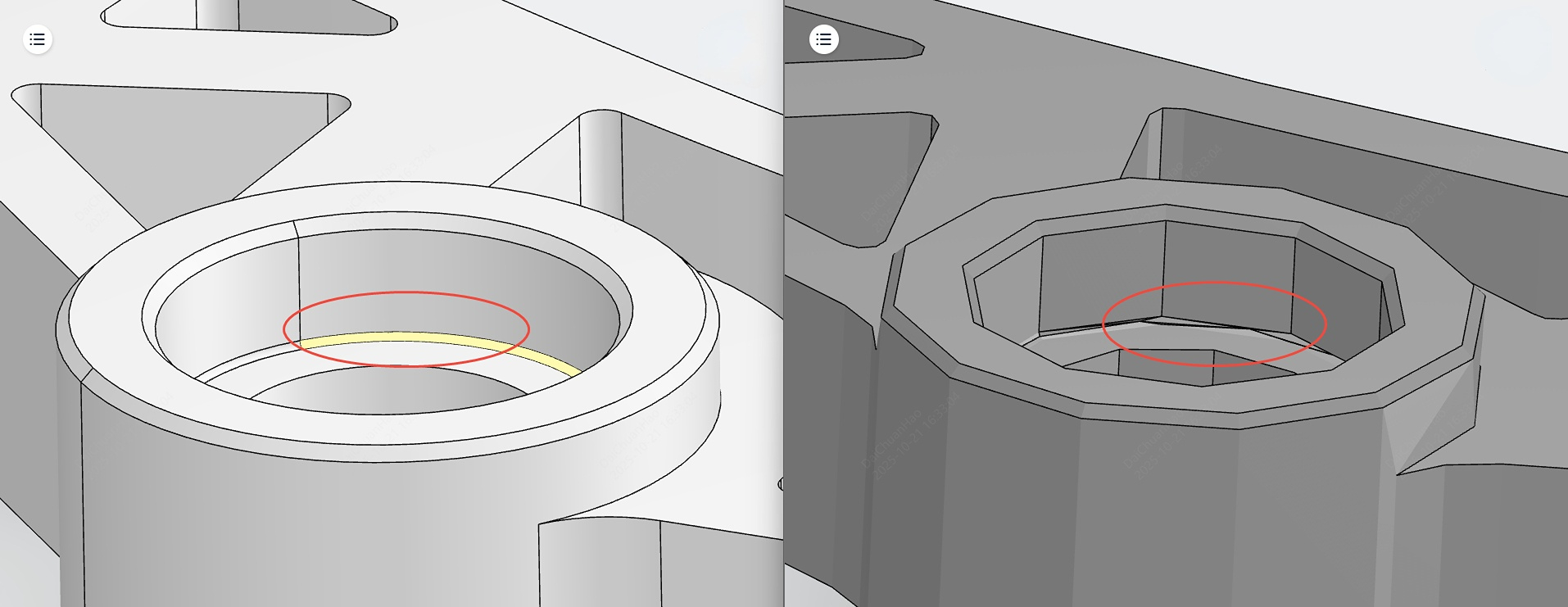
STL model surface defects
As shown in the figure above, surface defects may occur around the filleted area on the inner side of a circular hole in an STL model. A closer inspection of the model shows that surface defects tend to occur in areas where the geometry has already been distorted.
When two adjacent curved surfaces are distorted at the same time, the errors introduced by the two surfaces can accumulate. This further amplifies the overall geometric deviation and may eventually result in surface defects or gaps.
An STL model is a triangular mesh model. Therefore, when viewed at the microscopic level, small gaps or discontinuities between adjacent mesh facets may exist. Increasing the mesh resolution can reduce these gaps, but cannot completely eliminate them.
A finer mesh can also reduce the possibility of geometric distortion and therefore reduce the occurrence of surface defects. However, an excessively fine mesh requires significantly more computer processing resources.
Therefore, the appropriate mesh resolution should be selected according to the actual application requirements. Mesh quality is therefore also an important factor affecting the occurrence of surface defects.
In addition, some models are originally created using surface modeling, which may result in non-watertight surfaces. For example, certain modeling operations or options in Creo may result in incomplete surface geometry. When such a model is exported as an STL file, missing surface patches may appear as surface defects.
Conversely, some models may contain overlapping surface patches due to repeated copying, pasting, or duplication of surface elements during the modeling process. These overlapping surfaces may also result in surface defects in the exported STL file.
In general, surface defects in 3D models may be caused by the following factors:
- Curve or spline elements that cannot be properly interpreted or converted.
- Missing or duplicated surface patches.
- Insufficient mesh resolution or poor mesh quality.
- A large number of curved surface features.
- Excessively complex model geometry.

Precision CNC Machining Service
Professional manufacturing, fast turnaround, and quality assurance.