Sheet Metal 3D Model & 2D Engineering Drawing File Specification
Last updated on Sep 24, 2026
Important Note:
The 3D model is used for structure verification, bending simulation, assembly inspection, and process evaluation. The 2D engineering drawing serves as the technical baseline for manufacturing. Dimensions and features of the 3D model and 2D drawing must be identical. In case of any discrepancy between them, please revise the files until the content of the 3D model and 2D drawing is consistent.
1. 3D Model File Specifications
1.1 Supported File Formats
Format Requirements: .step / .stp. We recommend exporting STEP files with SolidWorks 2021 or older versions for better compatibility.
Assembly Requirements:
- Multiple parts with assembly relationships must be combined and exported as a single STEP file. Uploading multiple separate STEP files is not supported.
- If multiple independent STEP files are submitted, the system will assume no assembly relationship between parts, and we cannot guarantee proper fit of components.
- Only sheet-metal assemblies are accepted. Assemblies mixed with other CNC types of parts are not allowed.
1.2 Modeling Rules (Mandatory Requirements)
- Model using our available sheet thicknesses (0.5 / 0.8 /1.0 / 1.2 / 1.5 / 2.0 / 2.5 / 3.0 / 4.0 / 5.0 / 6.0).
- All part features must be solid modeled. Fasteners such as clinch nuts, BSO/BSOA studs and weld nuts shall be modeled with full geometry and height; unified solid modeling is recommended. If fasteners are simply inserted as assembly components, the order will be classified as an assembly order. Once file defects are found during manual review of assembly orders, files cannot be replaced directly. You will need to cancel the current order and resubmit a new order with updated files.
- Forming directions of fasteners, extruding, and other features shall be shown in the model for process review, enabling the production team to identify installation orientation.
- For parts requiring one-piece bending, all features must be modeled with the same sheet thickness.
- Models must not contain redundant tiny faces, overlapping faces, or broken surfaces, which will cause file parsing failures.
- Do not add notes or text descriptions inside the 3D model. All technical requirements shall be documented in the 2D engineering drawing.
- Only sheet metal parts are allowed in assemblies. CNC machined parts cannot be included (Sheet metal and CNC use separate production lines and cannot be manufactured together).
1.3 Model Self-Check Checklist (Pre-Order Verification)
- No overlapping solids, broken surfaces or tiny fragment faces in the model.
- The fasteners are fully modeled with clear specification information.
- Bending and fastener directions are correctly defined.
- Multi-part assemblies are combined and exported as a single STEP file.
- The file contains no extra reference parts or hidden invalid solids.
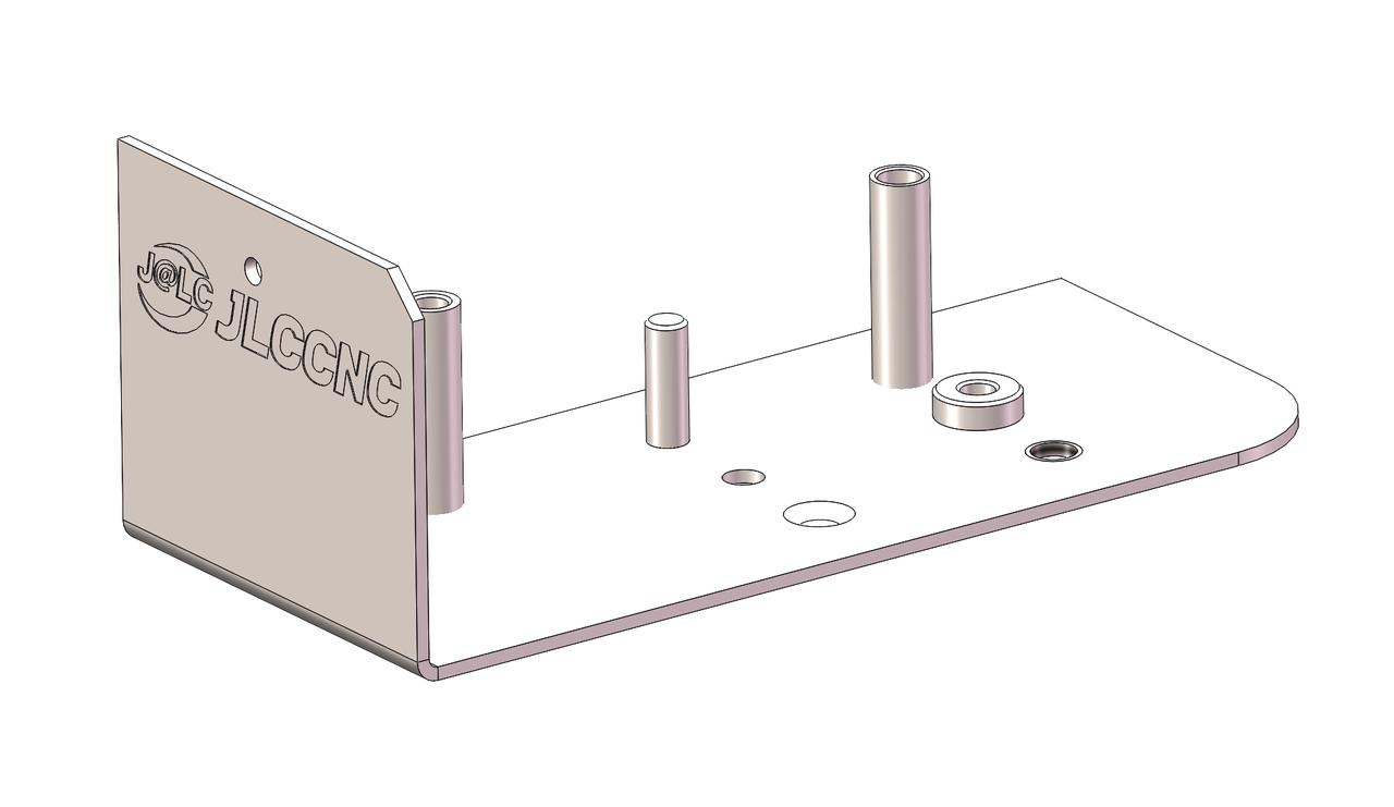
Refer to the 3D model sample drawing below:
2. 2D Engineering Drawing File Specifications
The 2D engineering drawing serves as the official manufacturing reference. All dimensions, tolerances, hole specifications and other details must be indicated on it.
2.1 Basic Drawing Requirements
- Supported formats: PDF, DWG, DXF, JPG, PNG. Not accepted: Gerber files as 2D engineering drawings
- Hole specifications shall be marked directly at hole locations. Describing hole information only via paragraphs is not allowed.
- Mark fastener specifications on drawings (Example: Blind Hole Rivet Nut Stud BSO-M3-6) and thread information. Only metric M specifications are accepted; imperial inch specifications are not supported.
- Mark critical dimensions, tolerances, and sheet thickness.
- If welding is required for the part, please upload engineering drawings with complete weld paths marked.
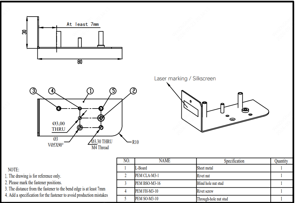
Refer to the 2D engineering drawing sample below:
2.2 Laser Marking / Silk Screen 2D Drawing File Specifications
Important: Separate DXF/DWG files in the flat view after bending must be submitted for silk screen and laser marking. The 2D engineering drawing cannot be used directly as the manufacturing source file.
Mandatory Process Constraints
- Solid double-line width ≥0.2mm
- Minimum text height ≥2.0mm
- Gap between characters ≥0.3mm
- Distance from text to bend edge/part outer edge ≥1.0mm
Color & Fill Requirements
- If fill colors are required, assign colors directly in the silk screen/laser marking file. For multi-color silk screen, use distinct colors to separate different regions.
- Solid fill is used by default for silk screen and laser marking. Hatch line fill is not accepted. Large-area silk screen or laser marking is not recommended, as it may lead to cosmetic defects.
Mandatory File Requirements
DXF/DWG files must contain the part outer contour and hole positions.
Refer to the silk screen/laser marking sample file below (examples of blue and black fill effects):