Types of CNC File Formats: How to Choose the Best Format for CNC
12 min
- What Files Are Used in CNC Machining?
- What Are the Common CAD File Formats for CNC Machining?
- Which File Format Is Best for CNC Machining?
- What Files Do You Need for a CNC Machining Quote?
- How to Prepare CNC Files Before Uploading
- CNC File Formats FAQs
- Conclusion About CNC File Formats
Key Takeaways
- STEP is a practical choice for most 3D CNC parts because it carries the part's solid and surface geometry.
- IGES can store surfaces, wireframes, and other CAD geometry. It is still used with older CAD/CAM files, while STEP is more common for current 3D models.
- STL stores the shape as a triangular mesh. It can be used when the source geometry is available only as a mesh, but it does not retain the exact solid geometry or parametric design information of the original CAD model.
- DXF is mainly used for 2D profiles such as plates, brackets, and sheet parts. It is also widely used for laser, plasma, and routing work.
- DWG is commonly used for CAD drawings, especially with AutoCAD. Its usefulness for CNC depends on whether the CAM software can read the required geometry.
- G-code is different from CAD formats. It contains the machine instructions produced after CAM programming, including tool movements, feed rates, spindle commands, and other CNC functions.
- For a basic 2D profile, DXF may be sufficient.
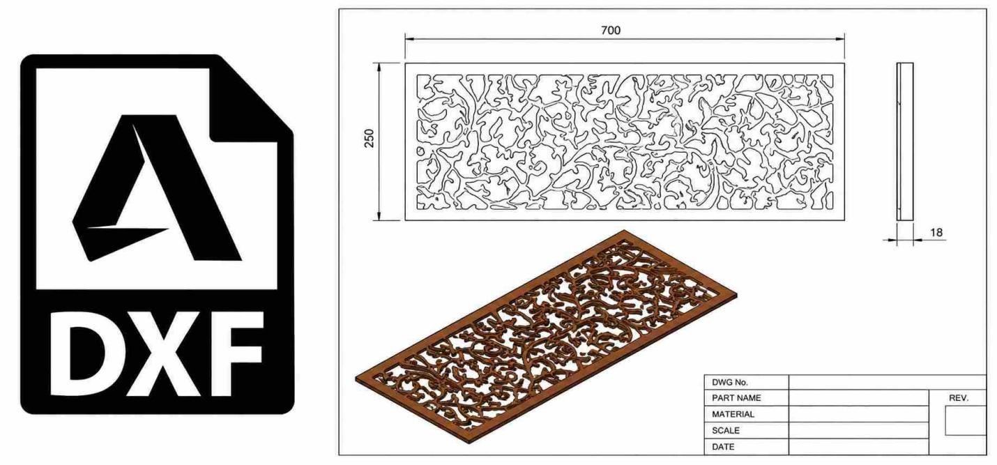
DXF file format for CNC engraving (Blue Elephant CNC)
"CNC file format" can refer to design/CAD files used for CAM programming or machine-code files generated for the CNC control. For most outsourced CNC machining jobs, the customer usually supplies a CAD model rather than G-code.
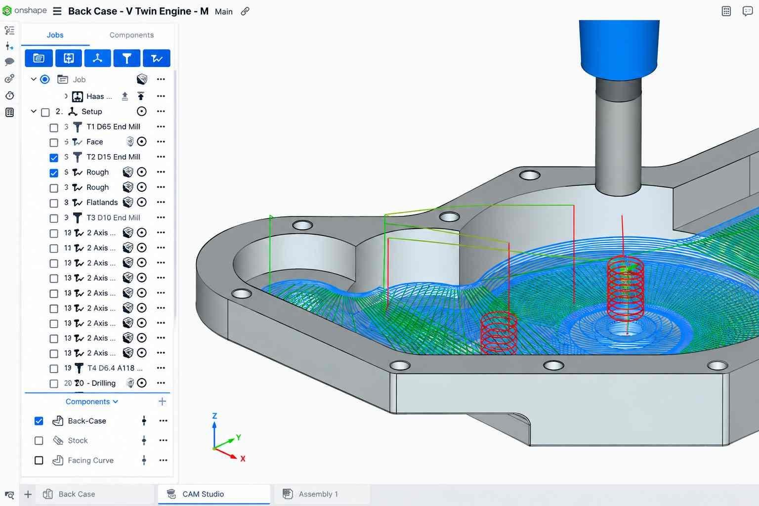
CAM File (PTC)
The right file format depends on the part being made. A housing with pockets, holes, curved surfaces, and other 3D features is best supplied as a 3D CAD model, such as STEP. A flat plate with a simple cut profile can often be supplied as a DXF, provided its thickness, material, tolerances, and other manufacturing requirements are specified separately.
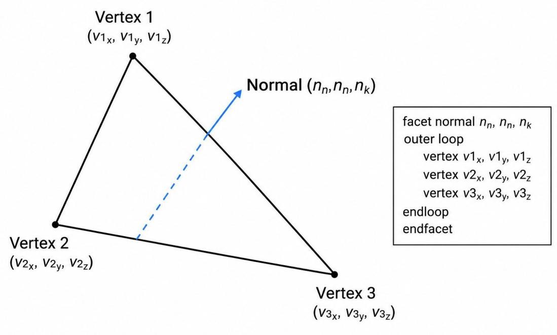
STL file format of a triangle (ResearchGate)
An STL can be useful for parts that exist only as mesh geometry, such as scanned or highly organic shapes. However, the programmer has less model information to work with compared with a proper solid CAD file.
For production, send the 3D model and engineering drawing together if the model does not show all the information needed to make the part. The drawing can add details such as:
- Dimensional tolerances
- Thread sizes and specifications
- Surface finish
- Material grade
- Critical dimensions
- Inspection requirements
What Files Are Used in CNC Machining?
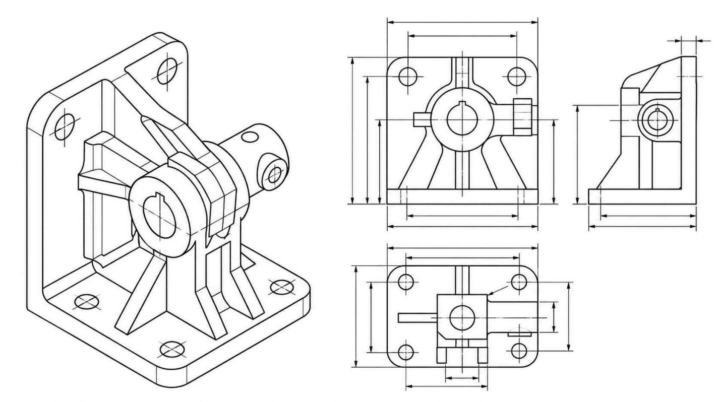
CAD file (TechDraw AI)
The CAD model defines the part geometry, while the CAM system uses that geometry to create machining operations and toolpaths.
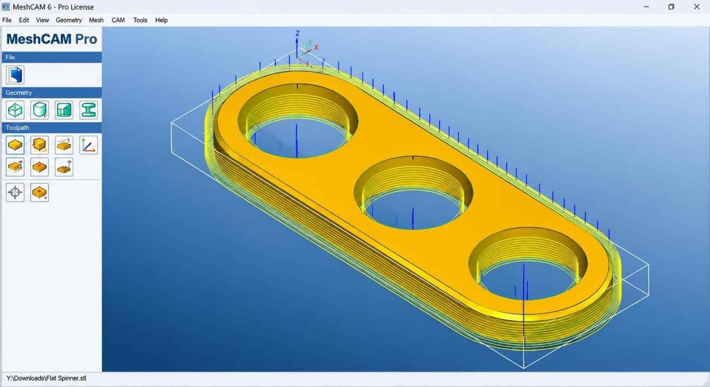
After the CAD model is imported, CAM software is used to define the machining operations, tools, feeds and speeds, and toolpaths. The CAM system then generates G-code or other machine-specific code for the CNC control.
The workflow can be summarized as follows:
- CAD: Part geometry and design
- CAM: Machining setup and toolpaths
- G-code: Machine control instructions
What Are the Common CAD File Formats for CNC Machining?
Common CNC file formats include STEP, IGES, Parasolid, native CAD files, DXF, DWG, and STL. Each one is used for a different type of CAD data.
STEP
STEP is a neutral 3D exchange format widely used to transfer solid and surface geometry between different CAD/CAM systems. It is a practical default for outsourced CNC machining when the designer and manufacturer use different CAD platforms.
IGES
IGES can transfer surfaces, wireframes, and some solid geometry. IGES is still used for legacy CAD data and surface-based models, although STEP is generally preferred for new 3D model exchange.
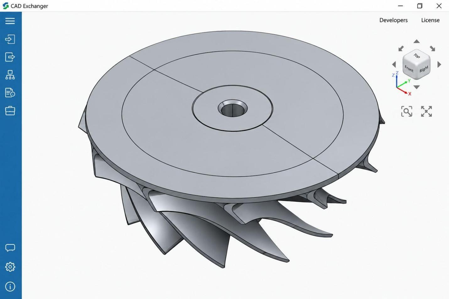
IGES File (FileInfo.com)
The main issue appears during data conversion. A complex model may import as separate surfaces instead of a closed solid. The programmer may then have to repair or join the surfaces before using the model for CAM programming.
Parasolid
Parasolid is particularly useful when the receiving CAD/CAM system supports it directly. If the manufacturer uses a different system, STEP is usually a safer neutral format because it has broader software support.
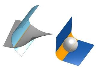
Parasolid (CAD Exchanger)
Native CAD Formats
Native CAD files are created and saved by specific CAD programs. Unlike neutral exchange formats, native CAD files can retain model-specific information such as feature history, sketches, parameters, constraints, and design relationships.
This information is useful if the CNC programmer needs to modify the model before programming. The limitation is software compatibility. A native file from one CAD system may not open directly in another, so a STEP file can be supplied alongside it for the manufacturing handoff.
DXF and DWG
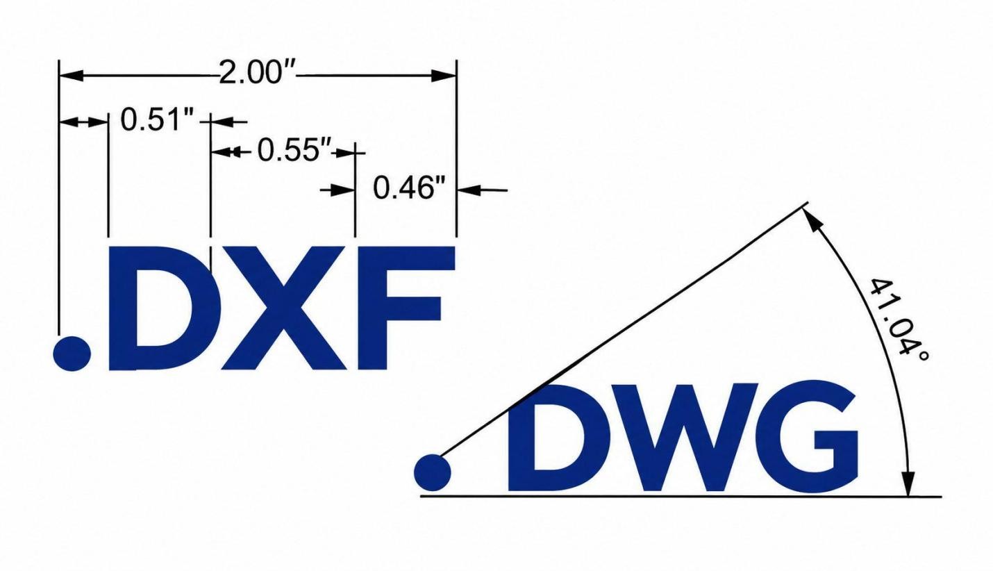
DXF vs DWG (Corel)
Main Difference
DXF is mainly used to exchange 2D geometry between CAD and manufacturing software. DWG is a broader CAD drawing format that can contain more design information.
For CNC work, the practical choice depends on the part:
- Flat profile: DXF is usually sufficient.
- 2D drawing with CAD design data: DWG may be suitable.
- 3D machined features generally require a 3D CAD model rather than a 2D exchange file.
A typical 2D DXF provides profile geometry for cutting or some 2.5D milling operations. It does not, by itself, specify stock thickness, pocket depths, or all other manufacturing requirements. DXF can also contain 3D entities, but STEP is generally a more practical choice for exchanging complete 3D machined-part geometry.
| Feature | DXF | DWG |
|---|---|---|
| Main use | 2D CAD data exchange | CAD drawing and design data |
| Common geometry | Lines, arcs, circles, curves | Lines, arcs, circles, curves, plus richer CAD data |
| CNC use | Common for 2D profiles and cutting | Can be used for 2D CNC work when supported by the CAM software |
| Typical parts | Plates, brackets, panels, sheet-metal profiles | 2D drawings, layouts, and CAD designs |
| 3D machining data | Limited | Can contain more CAD information, but CNC use depends on the software |
| CAM workflow | Often imported directly for profile toolpaths | May require CAD/CAM software that supports DWG |
| Best suited for | Simple 2D cutting profiles | CAD drawings and designs that use the DWG format |
STL
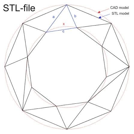
STL file format (Wikipedia)
STL represents a 3D part as a mesh of triangular faces. It is useful for organic shapes, scanned parts, and models that are already available as mesh data.
The quality of an STL depends on its mesh resolution. If the triangles are too large, curved surfaces can appear faceted in the machining path. A very dense mesh can also make the CAM file heavier and slower to process.
For standard CNC components with defined solid geometry, STEP is generally a better starting point than STL because it preserves mathematical solid and surface geometry rather than a triangular approximation.

Precision CNC Machining Service
Have a CNC part ready for machining? Upload your CAD file and engineering drawing to JLCCNC for a project-specific quote. JLCCNC can review the part for manufacturability and flag potential DFM issues before quoting.
Which File Format Is Best for CNC Machining?
For most 3D CNC machining work, STEP (.step/.stp) is a practical default because it transfers solid and surface geometry across different CAD/CAM systems. The manufacturer may still request another format based on its programming workflow.
The appropriate format depends on the geometry and the receiving CAD/CAM system:
- Use a 3D solid exchange format for standard 3D machining.
- Use a native CAD file when editable design features are required.
- Use a 2D format for profile-based work.
- Use a mesh format when the source geometry is mesh-based.
Before sending the file, check what the manufacturer accepts. Confirm the accepted formats with the manufacturer, and include the engineering drawing when the CAD model does not contain all manufacturing requirements. The drawing may contain dimensions and tolerances, threads, surface finish, material, and other requirements that are not obvious from the model.
What Files Do You Need for a CNC Machining Quote?
A CNC quote starts with the part geometry, then the manufacturer evaluates the specifications that affect machining, finishing, and inspection.
3D CAD Model
The 3D model lets the manufacturer review the actual part geometry before pricing the job. It shows geometric features such as holes, pockets, slots, bosses, fillets, and curved surfaces. Thread specifications may not transfer with the model geometry, so provide the thread designation, pitch, tolerance class, and required thread depth in the drawing or agreed manufacturing annotations.
The model also helps determine the machining approach. For example, the number of setups, required tool access, and type of cutting operations can change with the part geometry.
2D Engineering Drawing
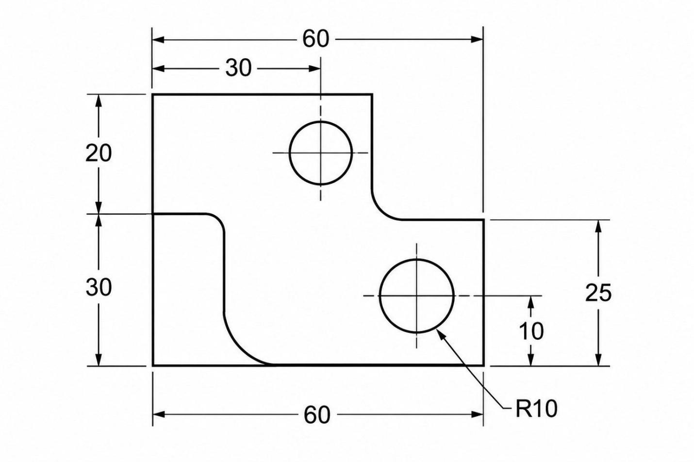
2D Mechanical Drawing (ASTCAD)
The drawing can define dimensions and manufacturing requirements that may not be fully represented in the 3D model. It can include dimensional tolerances, GD&T, surface-finish values, thread details, datums, and inspection requirements.
These details can change the quote. A part with several closely controlled dimensions may require additional machining passes and inspection compared with the same geometry having standard dimensional requirements.
Manufacturing Requirements and Supporting Documentation
For the quotation, provide the details that affect the machining and finishing work:
| Requirement | Information to provide |
|---|---|
| Material | Material grade and specification |
| Quantity | Number of parts required |
| Surface finish | Required finish value or finish type |
| Heat treatment | Treatment type and required condition |
| Coating | Anodizing, plating, passivation, etc. |
| Inspection | Inspection reports, certificates, CMM inspection, etc. |
| Standards | Any required manufacturing or inspection standard |
Anodizing, plating, passivation, and heat treatment should be specified as required manufacturing operations. Their position in the process depends on the material, required condition, and manufacturing route.
If you require material certificates or inspection reports, specify them at the same stage. This gives the manufacturer the information needed to price the complete part.
How to Prepare CNC Files Before Uploading
Take a quick look at the CAD file and drawing before sending them to the manufacturer. Check the model, units, and revision first. Small file issues can lead to questions during programming and quoting.
Check the Model Geometry
Open the model and look for gaps, missing faces, broken edges, duplicate bodies, and other unwanted geometry. Delete construction geometry that is not part of the finished part. If the part is supposed to be a solid, make sure the exported file still contains a complete solid body. For a more detailed checklist covering CAD geometry, file setup, and export requirements, see how to prepare CAD files for CNC machining.
Verify Units and Scale
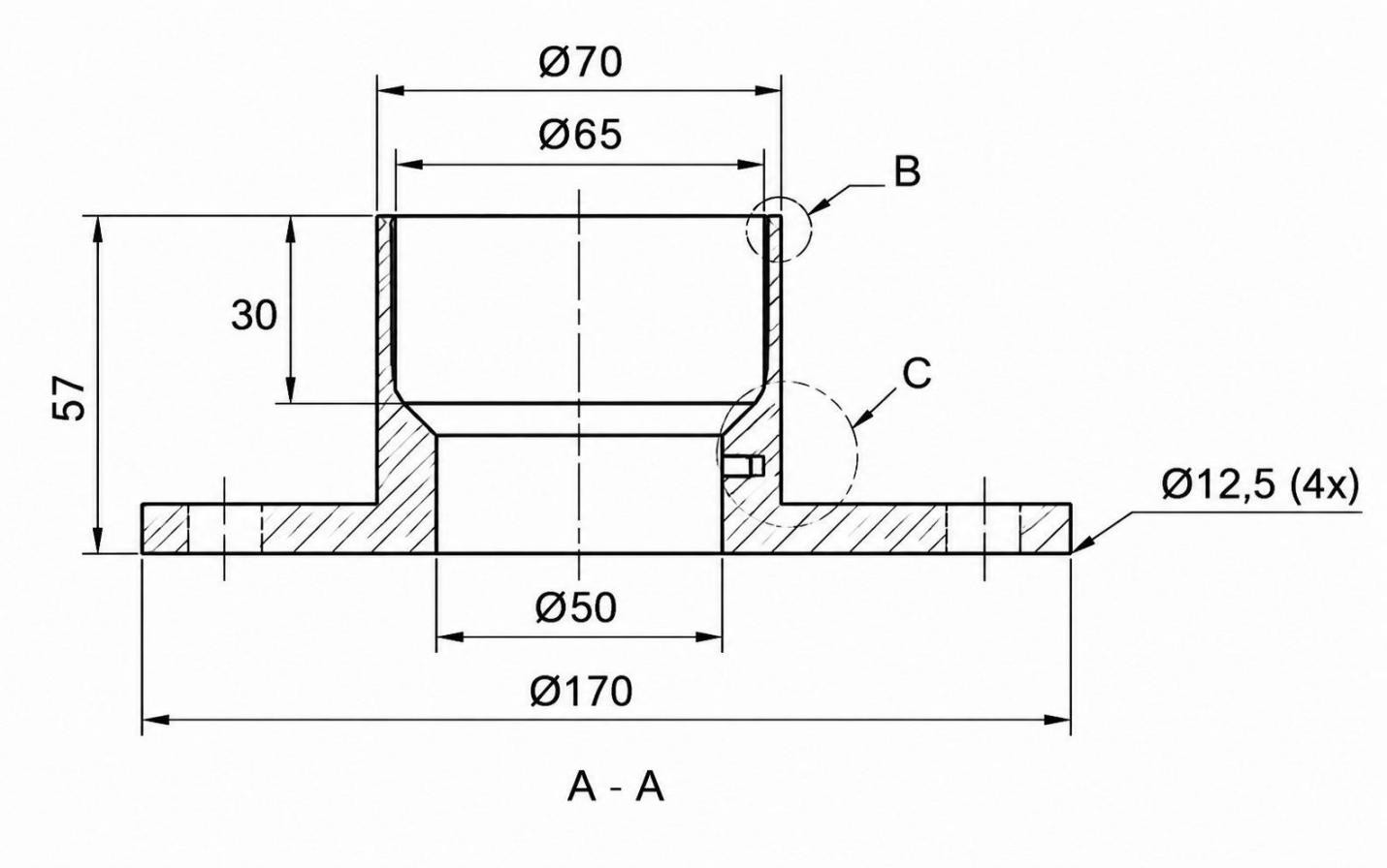
Engineering Drawing (DraftAid)
Check whether the file is in millimeters or inches. Then measure one known feature in the exported file and compare it with the original CAD model. This is a simple way to catch a scaling issue that occurs during export.
Match the CAD Model and Drawing
Check that the CAD model and drawing have the same revision before you send them.
- Compare the important part details, such as dimensions, hole locations, and thread specifications.
- Check the datums and GD&T callouts against the model.
- Make sure the surface finish requirements are shown correctly.
- If you find a difference between the drawing and the model, fix it first and then upload the final files.
Check the model orientation and coordinate system where relevant, especially if the file will be used for multi-axis machining or automated CAM workflows.
CNC File Formats FAQs
What File Format Do CNC Machines Use?
CNC machines execute an NC program, which commonly contains G-code and M-code commands for tool movements, feeds, spindle control, coolant, and other machine functions. STEP, IGES, and DXF files are normally used earlier in the CAD/CAM workflow to generate that program.
What Is the Best File Format for CNC Machining?
For most standard 3D machined parts, STEP is a practical choice because it provides transferable solid or surface geometry. The appropriate format still depends on the part geometry and the receiving CAD/CAM system.
Can CNC Machines Read STEP Files Directly?
STEP files contain CAD geometry rather than machine movements. The file normally goes into CAD/CAM software first, where the geometry is used to create toolpaths and generate the machine code required by the CNC control.
Can STL Files Be Used for CNC?
STL files describe a part as a triangular mesh. CAM software can use this mesh for machining freeform surfaces, models, and other mesh-based geometry. A STEP or Parasolid file is generally preferable when a proper solid model is available.
Is DXF Suitable for CNC Machining?
Yes. DXF is commonly used for profile cutting and some 2.5D milling operations. A typical 2D DXF defines outlines and feature boundaries, while thickness, machining depths, and other requirements must be supplied separately. For parts with complex 3D geometry, STEP is generally a more practical exchange format.
Do I Need a 2D Drawing for CNC Machining?
Provide a 2D drawing when the model and order specifications do not fully communicate the manufacturing requirements. This commonly includes specified tolerances, GD&T, threads, surface requirements, and inspection requirements. Make sure the drawing and CAD model use the same revision.
Conclusion About CNC File Formats
Before uploading a CNC file, make sure the model is complete, the revision matches the engineering drawing, and the required manufacturing information is included. A clear file package gives the manufacturer the information needed to review the part and prepare an accurate quote.
Precision CNC Machining Service
Need CNC machining for your part? Upload your CAD file and engineering drawing to JLCCNC for a project-specific quote. The submitted files can also be reviewed for manufacturability and potential DFM considerations before production.
Keep Learning
CAD to CNC: How to Turn Your CAD File into CNC-Machined Parts
CAD to CNC (Freepik) You’ve got your CAD design. It looks great on screen, tight tolerances, clean geometry, ready to go. But now what? How do you actually turn that file into a real, CNC-machined part? If you’re staring at your .STEP, .DWG, or .DXF file wondering what the next move is, you’re not alone. This guide breaks it all down: how to prep your CAD file, what CNC machines really need, and how to go from digital design to precision-machined reality, without wasting time, money, or materials. Wha......
Types of CNC File Formats: How to Choose the Best Format for CNC
Key Takeaways STEP is a practical choice for most 3D CNC parts because it carries the part's solid and surface geometry. IGES can store surfaces, wireframes, and other CAD geometry. It is still used with older CAD/CAM files, while STEP is more common for current 3D models. STL stores the shape as a triangular mesh. It can be used when the source geometry is available only as a mesh, but it does not retain the exact solid geometry or parametric design information of the original CAD model. DXF is mainl......
Computer Aided Design: How CAD Works, Types, and Uses
Key Takeaways Computer aided design (CAD) uses software to create, modify, analyze, and document 2D and 3D designs. 2D CAD is mainly used for drafting and documentation, while 3D CAD supports solid modeling, assemblies, simulation, and manufacturing workflows. Parametric and direct modeling offer different approaches to creating and modifying CAD geometry. Common CAD file formats include STEP and IGES for 3D geometry exchange, DWG and DXF for 2D drawings, and STL for 3D printing. In CNC machining, CAD......
A Comprehensive Guide to the Best Free CAM Software
In order to accommodate the various demands and tastes of people involved in CNC production, many kinds of CAM software proposals for CNC design have been introduced. Users may choose CAM software that fits their needs, be it a certain machining technique, industry specialization, or feature set, by investigating a variety of solutions. With this thorough approach, users are certain to be able to make well-informed judgments and identify the optimal CAM software solution for their CNC design requireme......
The Importance of Tool Path Optimization in CAM Software
In the field of CNC machining, CAM (Computer Aided Manufacturing) software is the core bridge between design and finished product, while toolpath optimisation is the key technology to ensure machining efficiency, accuracy and cost control. Whether it's 5-axis complex surface machining or batch part production, inefficient toolpaths can lead to double the machining time, a surge in tool wear and even part scrap. In this article, we will analyse the core logic of tool path optimization, and share how to......
A guide to choosing free CAM software
In modern manufacturing, CAM (Computer Aided Manufacturing) software has become an integral part of the CNC machining process.The primary role of CAM software is to convert design files into machine tool code to control CNC equipment for complex machining tasks. However, the high cost of paid CAM software can put a strain on individual users, small businesses and DIY designers. Fortunately, there are many free CAM software options available on the market that not only fulfill basic machining needs, bu......