Computer Aided Design: How CAD Works, Types, and Uses
20 min
- What Is Computer Aided Design?
- How Does the CAD Design Process Work?
- Types of CAD by Dimension and Modeling Method
- Computer Aided Design Software
- CAD Applications Across Industries
- Benefits and Limitations of CAD
- CAD in Manufacturing
- Common CAD File Formats
- CAD vs. CAM
- Conclusion: From CAD Design to Manufacturing
- FAQs About Computer Aided Design
Key Takeaways
- Computer aided design (CAD) uses software to create, modify, analyze, and document 2D and 3D designs.
- 2D CAD is mainly used for drafting and documentation, while 3D CAD supports solid modeling, assemblies, simulation, and manufacturing workflows.
- Parametric and direct modeling offer different approaches to creating and modifying CAD geometry.
- Common CAD file formats include STEP and IGES for 3D geometry exchange, DWG and DXF for 2D drawings, and STL for 3D printing.
- In CNC machining, CAD defines the part geometry, while CAM converts that geometry into tool paths and G-code for manufacturing.
- Manufacturing-ready CAD files should contain clean geometry and complete specifications, including dimensions, tolerances, materials, and surface requirements.
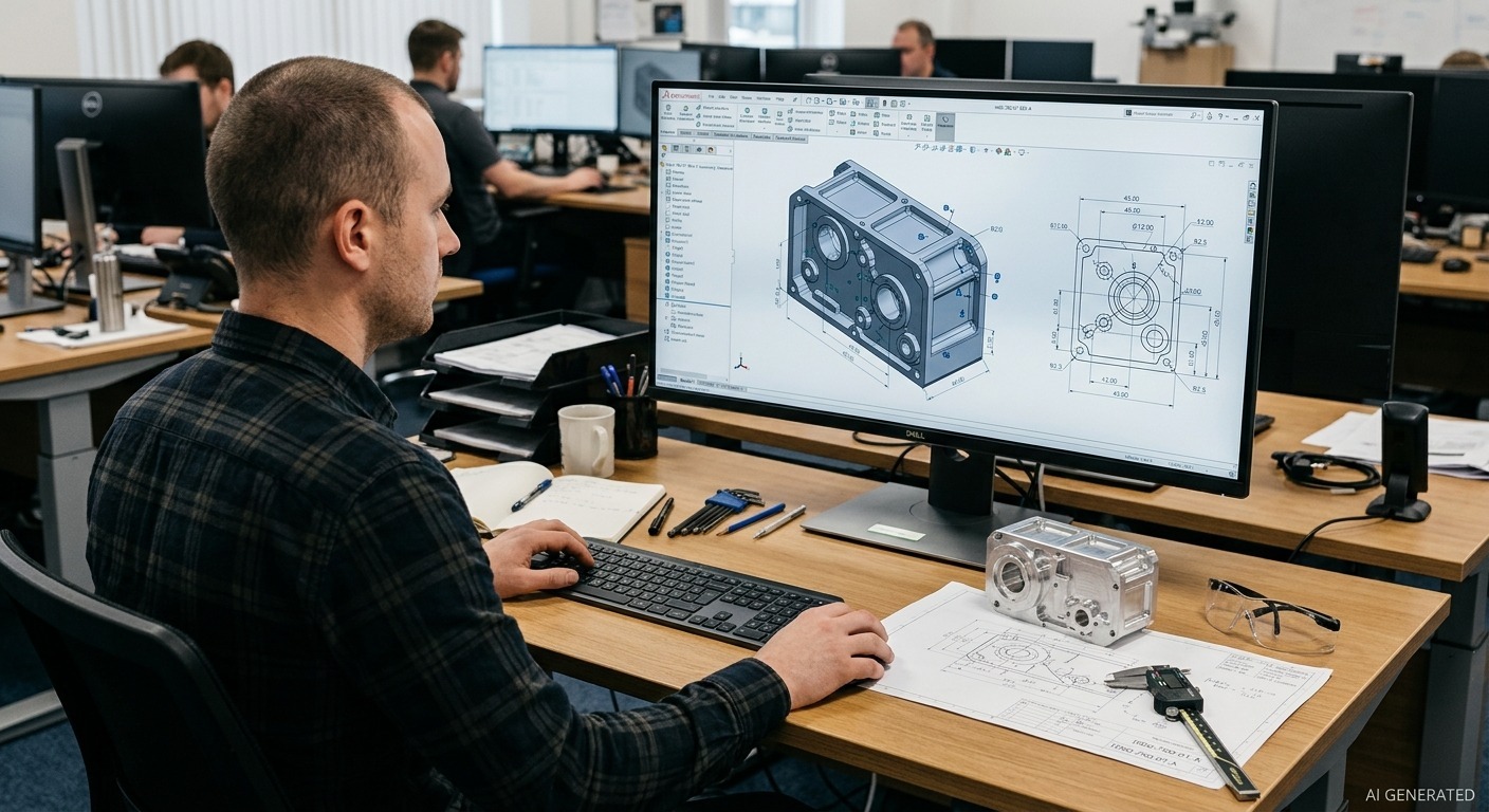
Mechanical designer working at a CAD workstation
Before Computer Aided Design (CAD), designing a part meant drawing it by hand. Designers relied on pencils and straightedges. A change to one dimension meant erasing and redrawing. A change to the overall geometry sometimes meant starting over. And if you needed the same drawing at a different scale, you did it again manually.
Computer aided design replaced most of that. Not instantly and not painlessly, the early CAD systems in the 1970s and 80s were expensive, difficult to learn, and not obviously better than a skilled draftsman for straightforward work. But the advantages accumulated. Today it's hard to imagine serious product development or manufacturing happening without CAD design at the center of it.
This guide covers what computer aided design actually is, how the CAD process works in practice, what the different types of CAD software do, and how CAD connects to manufacturing, including CNC machining.
What Is Computer Aided Design?
Computer aided design is the use of software to create, modify, analyze, and document designs for physical objects. That covers everything from a simple bracket drawn in 2D to a fully parametric 3D CAD model of a gas turbine engine with thousands of components.
The "computer aided" part used to be the interesting distinction. Now CAD is just how engineering design works. The meaningful distinctions are between types of CAD, modeling methods, and downstream uses. These uses include manufacturing, simulation, documentation, and visualization.
What CAD replaced wasn't just the physical act of drawing. It replaced a whole set of limitations that came with hand drafting: the difficulty of making changes, the challenge of visualizing three-dimensional geometry from two-dimensional drawings, the labor involved in producing multiple views of a complex part, and the risk of errors propagating through a drawing set without being caught. CAD doesn't eliminate all of those problems but it makes them much more manageable.
The other thing CAD does, maybe the most important thing from a manufacturing perspective, is create a digital definition of the design that can be directly passed to downstream processes. A 3D CAD model isn't simply a rotatable picture of a part. The geometric descriptions in it can be used by CAM software to generate machining tool paths, simulation software can be used to run structural analysis, and inspection software can be used to compare a manufactured part against its design intent. That downstream connectivity is where a lot of the real value lives.
For CNC machining projects, JLCCNC can check submitted CAD files against manufacturing standards before production. This helps identify geometry or specification issues that could affect manufacturing.

Precision CNC Machining Service
Professional manufacturing, fast turnaround, and quality assurance.
How Does the CAD Design Process Work?
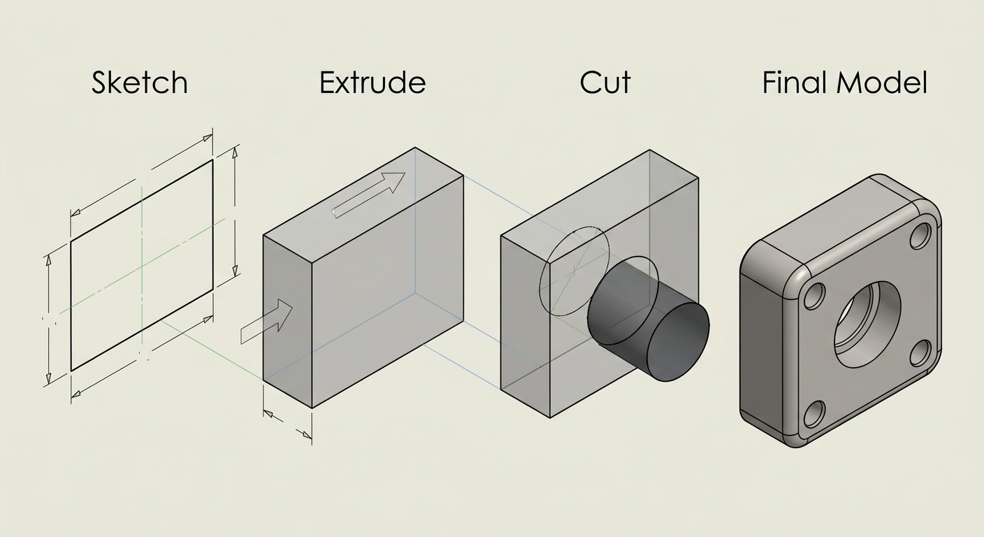
CAD workflow from 2D sketch to 3D solid
Creating a 2D Drawing or 3D Model
The starting point depends on what you're designing and for what purpose. 2D CAD design involves creating flat drawings, plan views, elevation views, cross-sections, using lines, arcs, circles, and annotation. This is still the standard in architecture and civil engineering, and it's still used for manufacturing drawings that communicate tolerances and specifications even when a 3D model exists.
3D CAD starts from a sketch, typically a 2D profile drawn in a plane, and builds geometry from there. Extrude a rectangle and you have a block. Revolve a profile around an axis and you have a turned part. Add a cut feature and you have a pocket or hole. The 3D model is built up from a sequence of operations, each defined geometrically and each modifiable after the fact.
Most serious product design today starts in 3D CAD. The 2D drawings are often derived from the 3D model rather than created independently.
Adding Dimensions, Constraints, and Features
A sketch in parametric CAD is constrained geometry. Two lines can be defined as parallel. A circle can be defined as tangent to a line. A dimension can lock a length to a specific value. These constraints mean the sketch behaves predictably when you change one dimension: the geometry updates to maintain all the defined relationships rather than breaking apart.
This is the core of parametric modeling. In a bolt circle, the holes can be defined as equally spaced around a central diameter. Change the diameter, and the holes move accordingly. Change the number of holes and the spacing recalculates. The model has design intent built in, not just geometry.
Reviewing and Modifying the Design
One of the genuine advantages of 3D CAD is what happens when the design needs to change, which it always does. Change a dimension in the feature tree and the model rebuilds. Modify a sketch and every feature that depends on it updates. Move a hole and the chamfer on the hole edge follows it.
This is not magic and it doesn't always work perfectly. Complex parametric models with many interdependencies can produce rebuild errors when changes are large or when the model wasn't structured well initially. But the ability to iterate quickly is genuinely transformative compared to hand drafting, where a significant change could mean hours of rework.
Review in modern CAD software often includes interference checking, verifying that components in an assembly don't overlap where they shouldn't, and section views that let you look inside a model to check internal geometry.
Exporting and Sharing Design Files
A 3D CAD model created in one software package doesn't automatically open in another. Native file formats, the proprietary format of a specific software, preserve all the parametric history and feature information but can only be fully opened in that software. Neutral exchange formats like STEP or IGES translate geometry into a format that most CAD systems can import, though usually without the parametric feature tree.
For manufacturing, CNC machining, 3D printing, laser cutting, the design file needs to be in a format the manufacturing software can work with. For CNC machining, STEP is commonly used to transfer 3D geometry into CAM software, where the geometry becomes the basis for machining operations and toolpath generation.
If you're preparing a CAD model specifically for machining, see our guide on how to prepare CAD files for CNC machining, including recommended file formats and the CAD-to-CNC workflow.
Types of CAD by Dimension and Modeling Method
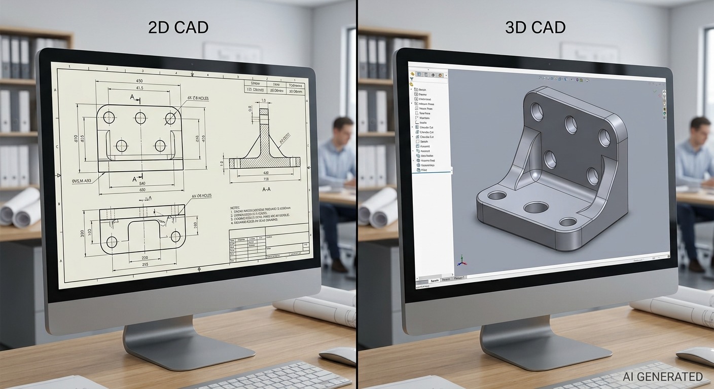
Comparison of 2D CAD and 3D CAD
2D CAD is mainly used for drafting, documentation, schematics, and flat profiles. In manufacturing, it remains useful for drawings that specify dimensions, tolerances, surface finishes, and other requirements.
3D CAD is better suited to complex product and mechanical design because it represents solid or surface geometry and supports assemblies, visualization, simulation, and downstream manufacturing workflows.
Parametric CAD
Parametric CAD uses parameters, constraints, and feature relationships to make models update when design dimensions change. It is widely used for mechanical and product design because it preserves design intent, although complex models can become difficult to rebuild when dependencies are poorly structured.
Direct Modeling CAD
Direct modeling (sometimes called explicit modeling) pushes and pulls geometry without a feature history. You select a face, move it, and the surrounding geometry adjusts. There's no rebuild, no feature tree, and no constraints to satisfy. SpaceClaim and the direct modeling modes in Fusion 360 and CATIA work this way.
Direct modeling is faster for certain tasks, modifying imported geometry that has no feature history, making quick changes to final models without caring about parametric relationships, and cleanup work. It's less suitable for design-intent-heavy work where you need controlled, repeatable modification behavior.
Solid and Surface Modeling
Solid modeling represents a part as a mathematically complete closed volume, the model knows it has an inside and an outside, can calculate mass properties, and can participate in interference checking with other solids. Most mechanical CAD is solid modeling.
Surface modeling constructs geometry as a collection of surfaces without necessarily defining a closed volume. It's used where the shape itself is the primary design challenge, car body styling, consumer product aesthetics, complex organic forms, and where the geometric quality of individual surfaces matters more than the solid volume they eventually enclose. CATIA and Alias are the tools most associated with class-A surface modeling in automotive and consumer product design.
In practice, most mechanical CAD software supports both, and complex parts often use surface modeling for difficult geometry that then gets combined with solid features.
Computer Aided Design Software
There's a lot of CAD software. The landscape splits roughly along industry lines, complexity levels, and whether you need parametric history, direct modeling, surface modeling, or some combination.
Common CAD Software
AutoCAD, the original mainstream CAD design software, still widely used for 2D drafting and documentation. Has had 3D capability for decades but remains primarily a 2D tool in practice.
SolidWorks, dominant in mechanical and industrial design, particularly in small-to-medium manufacturers. Strong parametric solid modeling, large user community, extensive learning resources. Windows-only.
Fusion 360, Autodesk's cloud-based CAD/CAM/CAE package. Popular with small companies, startups, and hobbyists due to its lower entry cost and integrated CAM capabilities. Parametric solid modeling with direct modeling and surface capabilities.
CATIA, the high end of the market. Aerospace, automotive, complex industrial design. Extremely capable, extremely expensive, long learning curve. CATIA is widely used in aerospace and automotive engineering, including applications at major aerospace manufacturers . Most people don't need it.
Siemens NX, similar tier to CATIA. Strong in automotive and aerospace. Integrated CAM is particularly well-regarded.
PTC Creo, formerly Pro/ENGINEER. Strong parametric modeling, widely used in industrial manufacturing. Known for being powerful and somewhat unforgiving to learn.
FreeCAD, open-source parametric 3D CAD. Free, cross-platform, improving rapidly. Not at the same level as commercial software for complex work but genuinely useful for many applications.
Onshape, fully browser-based parametric CAD. No installation, version-controlled by default, collaborative. Growing adoption in product design and education.
Choosing CAD Software for Different Applications
There's no universally right answer. For learning CAD or early-stage product work, Fusion 360 covers enough ground at low cost. For manufacturing-focused mechanical design, SolidWorks is the safe choice in terms of industry familiarity and machinist/supplier compatibility. For architecture, Revit or ArchiCAD. For consumer product styling, Alias or CATIA surfaces. For hobbyist and open-source work, FreeCAD or OpenSCAD.
The file format landscape means you're rarely completely locked in. STEP and IGES allow geometry to move between packages, even if parametric history doesn't travel with it.
CAD Applications Across Industries
Mechanical and Product Design
This is the heartland of 3D CAD. Mechanical engineers and product designers use CAD design to develop everything from simple fastener-retained housings to complex mechanisms with many moving parts. The ability to check how parts fit together in an assembly, verify clearances, and analyze motion before anything gets manufactured is genuinely valuable and not something that existed at scale before CAD.
Manufacturing and Engineering
Manufacturing engineering uses CAD both to design tooling, fixtures, and process equipment, and to review product designs for manufacturability. The same 3D model that the product designer works in becomes the input for the manufacturing engineer checking whether the geometry can be made, whether there's tool access for CNC operations, whether wall thickness is adequate for the intended process, whether tolerances are realistic.
Architecture and Construction
Architecture uses CAD primarily through BIM (Building Information Modeling) tools, Revit being the dominant example, that extend 3D CAD with building-specific information: materials, structural properties, mechanical systems, scheduling. A BIM model is not just geometry but a database of building information.
2D CAD in architecture never fully went away. Construction documentation, site plans, and many drawings are still 2D. But 3D design for visualization, clash detection, and coordination with structural and MEP systems is now standard on most significant building projects.
Automotive and Aerospace
Both industries push the upper boundary of CAD capability. Automotive design involves complex surface work for body styling alongside detailed mechanical engineering for powertrain, chassis, and interior systems. A modern vehicle can contain tens of thousands of components, with many of them defined and managed through CAD and PDM systems.
Aerospace is similar in complexity with the addition of tight integration between CAD geometry and structural analysis. A wing surface may look like it’s for aesthetic shape, but it has aerodynamic and structural requirements that the CAD geometry directly feeds into analysis tools.
Electronics and Other Industries
PCB design uses specialized EDA software that's its own CAD-adjacent category. Enclosure design for electronics products typically happens in mechanical CAD. Medical device design often uses mechanical CAD alongside extensive regulatory documentation. CAD models, revisions, and related records may form part of the design documentation maintained for regulatory compliance.
Benefits and Limitations of CAD
Benefits of CAD
Speed of iteration is the most practically significant benefit. Changing a dimension takes seconds. In hand drafting that change might have required significant rework. This speed makes it economical to explore more design options and respond to feedback faster.
Accuracy: A CAD model represents geometry precisely, while specified tolerances define the acceptable variation for manufacturing. Dimensions are exact, not approximate. Derived measurements like area, volume, and mass properties are calculated automatically from the geometry. Clearly specified dimensions and tolerances provide a consistent manufacturing reference for everyone working from the drawing.
Visualization: Complex 3D geometry can be shown in perspective views, sectioned, rendered with materials and lighting, and animated. Communicating design intent to people who can't read engineering drawings is much more practical with 3D CAD.
Reusability: Standard components, common features, and established designs get reused rather than redrawn. Libraries of standard parts, configurations of a base model, and design templates all reduce the work of creating similar designs.
Integration: The CAD file is the input for simulation, CAM, inspection, rendering, and documentation. One geometry source, many downstream uses.
Limitations of CAD
The learning curve is real. Professional-level parametric CAD takes time to learn properly, not just the software interface but the discipline of building models that remain editable when the design changes. A poorly structured parametric model can be harder to modify than a hand drawing.
Software cost. Professional CAD design software licenses, SolidWorks, CATIA, NX, are expensive. This is less of a barrier than it was before Fusion 360 and other lower-cost options, but still a real consideration for small teams.
CAD is still a representation, not the thing itself. The model can be geometrically perfect and still not capture something important about how the physical part will behave, surface finish effects, material anisotropy from manufacturing processes, residual stress. The model informs manufacturing; it doesn't replace engineering judgment about what will actually work.
CAD in Manufacturing
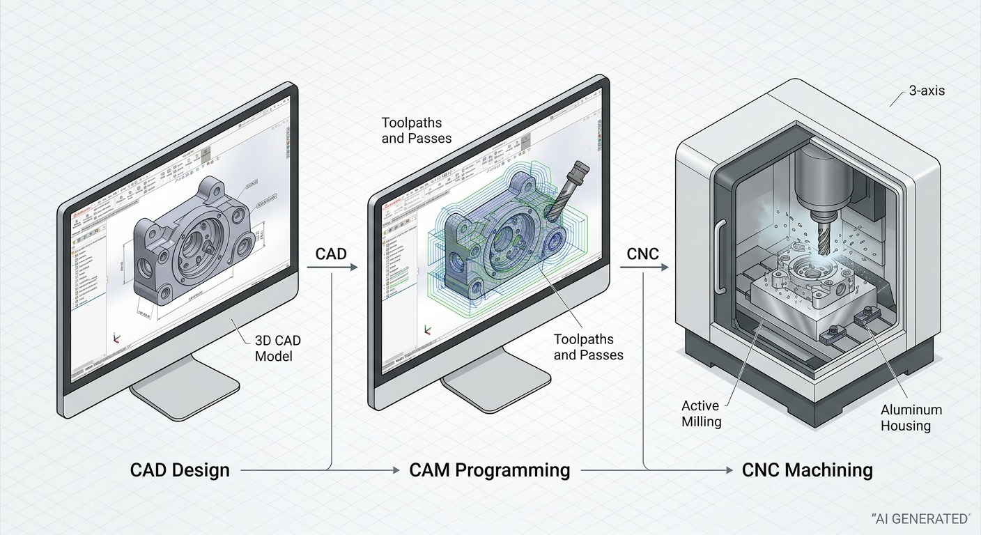
CAD design to CNC machining
CAD for CNC Machining
In CNC machining, CAD geometry quality directly affects downstream programming. Clean geometry, valid surfaces, and well-defined features can reduce the need for geometry repair before machining.
When you submit a STEP file to a machining service, the machinist's CAM software imports that geometry and works from it directly.
To see what happens after a STEP file leaves the CAD environment, read our guide on from STP file to finished CNC part
A good STEP file means the programmer can start generating tool paths quickly. A STEP file with bad geometry can create problems before machining can start. Open surfaces, duplicate faces, and tiny slivers from poorly built CAD may all require correction before CAM programming.
Preparing Manufacturing-Ready Models and Drawings
The 3D model and the 2D engineering drawing serve different purposes in many manufacturing workflows. For precision CNC work, suppliers commonly use the model for geometry and the drawing for tolerances, finishes, and other specifications.
Manufacturing-ready CAD means the model is clean of geometry errors, the file is in a format the manufacturing process can use, and the design has been reviewed for manufacturability, tool access for CNC, wall thickness for 3D printing, bend radii for sheet metal. Getting this preparation right before submitting for manufacturing avoids questions, delays, and parts that don't meet the design intent.
For a deeper look at designing parts around real manufacturing constraints, see our guide to Design for Manufacturing (DFM)
Design Information Needed for Production
For precision CNC machining, suppliers commonly need:
- A 3D model for part geometry
- A 2D drawing for critical dimensions, tolerances, GD&T, and finishes
- Material and surface treatment requirements
- Any inspection or packaging requirements
Common CAD File Formats
DWG and DXF
DWG is AutoCAD's native format and is widely used for 2D CAD design drawings. DXF is a more open exchange format for 2D geometry. Both are used extensively for 2D documentation and for flat geometry going to laser cutting, plasma cutting, or waterjet, where the 2D profile is the cutting path.
STEP and IGES
STEP (Standard for the Exchange of Product Data, file extension .step or .stp) is the dominant neutral format for 3D CAD geometry exchange. Almost every CAD package exports STEP, and almost every manufacturing software imports it. For CNC machining, STEP is a common standard for 3D geometry exchange. For 3D printing, STL and 3MF are also widely used, depending on the service and workflow.
IGES is an older neutral format with a similar purpose. It is still widely accepted, but STEP is generally preferred when both are available. STEP also tends to provide more reliable geometry exchange, especially for complex surface geometry.
STL
STL represents geometry as a mesh of triangles, no parametric information, no feature history, just a surface described by triangular facets. One of the most widely used formats for 3D printing file submission. Also used in early FEA meshing and in some reverse engineering workflows. The triangular representation means STL files can have faceting artifacts at curved surfaces if the tessellation resolution is too low.
Native CAD Files and 2D Engineering Drawings
Native files, .sldprt for SolidWorks, .f3d for Fusion 360, .prt for NX, preserve the full parametric model with feature history. They're valuable for ongoing design work and necessary if someone needs to make changes to a model, but they require the same software to fully open.
CAD vs. CAM
CAD, or computer aided design, creates the digital definition of a part. CAM, computer aided manufacturing, uses that definition to generate instructions for manufacturing equipment.
In CNC machining, CAM software imports the 3D CAD model, the programmer defines the machining operations and tool paths, and the CAM software generates G-code, the numerical instructions that control the CNC machine. CAD defines what to make. CAM defines how to make it.
They're separate software categories though increasingly integrated. Fusion 360 has CAM built into the same environment as the CAD. SolidWorks users often use HSMWorks or SolidCAM integrated CAM plugins. High-end operations use standalone CAM packages like Mastercam, Hypermill, or Siemens CAM.
The distinction matters for understanding what file format manufacturing needs. The machinist doesn't run CAD files on the CNC machine, they run G-code generated by CAM from those files. The 3D CAD model is an intermediate document, not the final manufacturing instruction. Understanding this helps explain why geometry quality in the CAD model matters: bad geometry makes CAM programming harder and sometimes produces incorrect tool paths.
Conclusion: From CAD Design to Manufacturing
Computer aided design has become a central part of modern engineering because it provides a reusable digital definition of a product. Beyond creating geometry, CAD supports documentation, simulation, collaboration, and downstream manufacturing workflows.
For CNC machining, the most important practical considerations are clean geometry, appropriate file formats, and complete manufacturing specifications.
At JLCCNC, CAD files are reviewed as part of the engineering process on every order, checking for geometry issues, manufacturability concerns, and specification completeness before production starts. STEP files for CNC machining and 3D printing, DXF for laser cutting, STL for 3D printing where appropriate.
Precision CNC Machining Service
Professional manufacturing, fast turnaround, and quality assurance.
FAQs About Computer Aided Design
Q: What is computer aided design (CAD) used for?
CAD is used to design, document, and communicate the geometry of physical objects. In engineering and manufacturing, it produces 3D models and 2D drawings used to define parts and assemblies for production.
Q: What is the difference between 2D CAD and 3D CAD?
2D CAD creates flat drawings, views, sections, and annotations, that represent geometry on a plane. 3D CAD creates solid or surface models in three dimensions that can be viewed, analyzed, and manipulated as three-dimensional objects. Most modern product and mechanical design works in 3D CAD, with 2D drawings derived from the model for manufacturing documentation. Some disciplines, particularly architecture and civil engineering, still use 2D CAD extensively for documentation.
Q: What are the most common CAD software programs?
AutoCAD for 2D and general drafting. SolidWorks for mechanical and industrial design. Fusion 360 for product design and integrated CAM. CATIA and Siemens NX for high-complexity aerospace and automotive work. Revit for architecture and building design.FreeCAD is an open-source option, while Onshape offers browser-based CAD with free and paid plans. The right choice depends on the industry, the complexity of the work, and the budget.
Q: What are the most common CAD file formats?
STEP (.step, .stp) for 3D geometry exchange between software packages and for manufacturing submissions. DXF and DWG for 2D drawings and flat cutting geometry. STL for 3D printing. Native formats (like .sldprt for SolidWorks) for full parametric model sharing within the same software. PDF for 2D engineering drawing documentation.
Q: How is CAD used in CNC machining and manufacturing?
The 3D CAD model is imported into CAM software, which generates the tool paths and G-code that control the CNC machine. The CAD model defines the geometry; CAM defines the machining strategy. Separately, 2D engineering drawings derived from the CAD model specify tolerances, surface finishes, and other requirements that the machinist works to. For precision CNC work, suppliers commonly use the 3D model for geometry and the engineering drawing for tolerances, finishes, and other specifications.
Keep Learning
CAD to CNC: How to Turn Your CAD File into CNC-Machined Parts
CAD to CNC (Freepik) You’ve got your CAD design. It looks great on screen, tight tolerances, clean geometry, ready to go. But now what? How do you actually turn that file into a real, CNC-machined part? If you’re staring at your .STEP, .DWG, or .DXF file wondering what the next move is, you’re not alone. This guide breaks it all down: how to prep your CAD file, what CNC machines really need, and how to go from digital design to precision-machined reality, without wasting time, money, or materials. Wha......
Types of CNC File Formats: How to Choose the Best Format for CNC
Key Takeaways STEP is a practical choice for most 3D CNC parts because it carries the part's solid and surface geometry. IGES can store surfaces, wireframes, and other CAD geometry. It is still used with older CAD/CAM files, while STEP is more common for current 3D models. STL stores the shape as a triangular mesh. It can be used when the source geometry is available only as a mesh, but it does not retain the exact solid geometry or parametric design information of the original CAD model. DXF is mainl......
Computer Aided Design: How CAD Works, Types, and Uses
Key Takeaways Computer aided design (CAD) uses software to create, modify, analyze, and document 2D and 3D designs. 2D CAD is mainly used for drafting and documentation, while 3D CAD supports solid modeling, assemblies, simulation, and manufacturing workflows. Parametric and direct modeling offer different approaches to creating and modifying CAD geometry. Common CAD file formats include STEP and IGES for 3D geometry exchange, DWG and DXF for 2D drawings, and STL for 3D printing. In CNC machining, CAD......
A Comprehensive Guide to the Best Free CAM Software
In order to accommodate the various demands and tastes of people involved in CNC production, many kinds of CAM software proposals for CNC design have been introduced. Users may choose CAM software that fits their needs, be it a certain machining technique, industry specialization, or feature set, by investigating a variety of solutions. With this thorough approach, users are certain to be able to make well-informed judgments and identify the optimal CAM software solution for their CNC design requireme......
The Importance of Tool Path Optimization in CAM Software
In the field of CNC machining, CAM (Computer Aided Manufacturing) software is the core bridge between design and finished product, while toolpath optimisation is the key technology to ensure machining efficiency, accuracy and cost control. Whether it's 5-axis complex surface machining or batch part production, inefficient toolpaths can lead to double the machining time, a surge in tool wear and even part scrap. In this article, we will analyse the core logic of tool path optimization, and share how to......
A guide to choosing free CAM software
In modern manufacturing, CAM (Computer Aided Manufacturing) software has become an integral part of the CNC machining process.The primary role of CAM software is to convert design files into machine tool code to control CNC equipment for complex machining tasks. However, the high cost of paid CAM software can put a strain on individual users, small businesses and DIY designers. Fortunately, there are many free CAM software options available on the market that not only fulfill basic machining needs, bu......