Design for Manufacturing (DFM): Principles, Guidelines, and Cost Reduction Strategies
19 min
- What Is Design for Manufacturing (DFM)?
- Why Design for Manufacturing Matters
- How Design for Manufacturing Reduces Manufacturing Cost
- Core Principles of Design for Manufacturing
- DFM Considerations Across Manufacturing Processes
- Material Selection in DFM
- Common Design Features That Increase Manufacturing Cost
- Conclusion About Design for Manufacturing
- FAQ About Design for Manufacturing
Key Takeaways About DFM
- Design for manufacturing (DFM) is the process of designing products that are easier, faster, and less expensive to manufacture.
- Good DFM design reduces production cost long before a part reaches the factory floor.
- Most manufacturing costs are locked in during the design phase, not during production.
- Following proven design for manufacturing guidelines helps reduce machining time, material waste, tooling complexity, and assembly issues.
- Effective DFM improves product quality, shortens lead times, and reduces production risk.
- Design for manufacturability is one of the highest ROI engineering activities because small design decisions can eliminate thousands of dollars in downstream manufacturing costs.
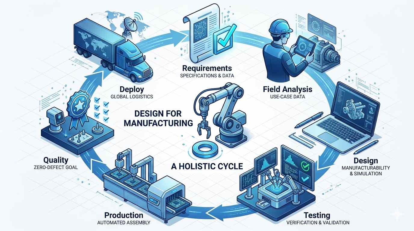
(AI generated) Design for manufacturing workflow and production cycle
You send out a CAD model that looks absolutely flawless on your screen, only to get a quote back that’s three times your budget. Then come the inevitable emails from the machinist asking for design changes, lead times double, and features that seemed perfect in CAD suddenly become massive headaches in production.
That’s why DFM matters. You can’t judge a part solely on how well it simulates; it has to be practical to machine at scale. A perfect design that costs too much to actually build is just a failed design.
Good DFM means designing for the machine tool from day one. If you catch these geometric bottlenecks early, you keep your parts functional and reliable without paying a premium for impossible tolerances or complex setups.
What Is Design for Manufacturing (DFM)?
Design for manufacturing (DFM) is the engineering practice of designing products so they can be manufactured more easily, consistently, and cost-effectively while maintaining required performance and quality.
DFM asks a simple question:
"Can this product be made efficiently in the real world?"
A design might function perfectly in simulation while still being difficult, slow, or expensive to manufacture. DFM identifies those issues before production begins.
Good design for manufacturability considers manufacturing limitations during product development rather than discovering them after tooling, machining, or production has already started.
Engineers use DFM to evaluate:
- Material selection
- Feature complexity
- Manufacturing processes
- Tolerance requirements
- Assembly requirements
- Production scalability
The goal of DFM design is not to compromise product performance.
The objective is to meet performance requirements while reducing manufacturing complexity wherever possible.
This is why experienced manufacturers frequently perform a DFM review before production starts. Many expensive problems are far easier to fix in CAD than on the shop floor.
DFM vs Design for Assembly (DFA)
Engineers often use DFM and DFA together, but they solve different problems.
Design for manufacturing focuses on making individual parts easier to produce.
Design for Assembly (DFA) focuses on making products easier to assemble.
For example:
A CNC housing with simplified internal geometry follows good design for manufacturing guidelines because it reduces machining time.
A product redesigned to use four fasteners instead of twelve follows DFA principles because assembly becomes faster.
The best products combine both approaches.
Many organizations refer to the combined methodology as DFMA (Design for Manufacturing and Assembly).
The manufacturing team cares about how easily parts can be produced.
The assembly team cares about how easily those parts fit together.
A strong DFM design strategy considers both.
Why Design for Manufacturing Matters
The biggest misconception about manufacturing cost is that it is controlled by purchasing departments or production managers.
It isn't.
Most manufacturing costs are determined by engineering decisions made months before production starts.
A hole location.
A tolerance callout.
A material choice.
A wall thickness.
A corner radius.
Each seemingly small decision influences how much effort manufacturing requires.
Research consistently shows that the majority of product cost is committed during design, often before the first prototype is built.
This is why design for manufacturing has such a significant impact on profitability.
Applying proper design for manufacturability principles early helps prevent costly redesigns, delays, quality issues, and production bottlenecks later.
Product Quality
Good manufacturing starts with good design.
Many quality problems are actually design problems disguised as production issues.
Consider a machined aluminum part with unnecessarily tight tolerances on every feature.
The machine shop can produce it.
But process variation becomes harder to control.
Inspection becomes more difficult.
Scrap rates increase.
Costs rise.
A better DFM design identifies which dimensions truly matter and relaxes non-critical requirements.
The result is often better consistency and higher overall quality.
Following established design for manufacturing guidelines also improves repeatability between production runs.
The easier a part is to manufacture, the more consistently it can be produced.
That's one reason why mature manufacturing organizations invest heavily in DFM reviews before releasing products.
Production Efficiency
Every manufacturing process has limits.
| Manufacturing Process | Design Constraint | DFM-Friendly Design Approach | Manufacturing Benefit |
|---|---|---|---|
| CNC Machining | Tool access requirements | Use internal radii that match standard end mill sizes, reduce deep pockets, avoid unnecessary undercuts | Shorter cycle times, lower tooling costs, easier machining |
| Injection Molding | Draft angle requirements | Add proper draft angles and simplify part geometry | Easier part ejection, lower tooling wear, fewer defects |
| Sheet Metal Fabrication | Bending limitations | Design around minimum bend radii and simplify formed features | Improved bend accuracy, reduced distortion, faster fabrication |
| Additive Manufacturing (3D Printing) | Support and orientation constraints | Optimize part orientation and minimize support-dependent features | Less support material, shorter print times, easier post-processing |
| Cross-Process DFM Principle | Manufacturing capability limitations | Align geometry with the strengths and limitations of the chosen process | Reduced production complexity, lower costs, improved manufacturability |
Manufacturing Risk
Every unnecessary complexity increases risk.
Complex parts generally have:
- More setup requirements
- More machining operations
- More inspection steps
- More opportunities for errors
Manufacturing risk isn't limited to defects.
It also includes:
- Missed deadlines
- Tool breakage
- Supply chain issues
- Yield losses
- Assembly failures
One of the primary goals of DFM design is risk reduction.
Following proven design for manufacturing guidelines helps engineers eliminate fragile features, difficult processes, and unnecessary production challenges before they become expensive problems.
The best DFM strategies focus on predictability.
Predictable manufacturing leads to predictable quality, predictable schedules, and predictable costs.
And predictability is incredibly valuable in production environments.
How Design for Manufacturing Reduces Manufacturing Cost
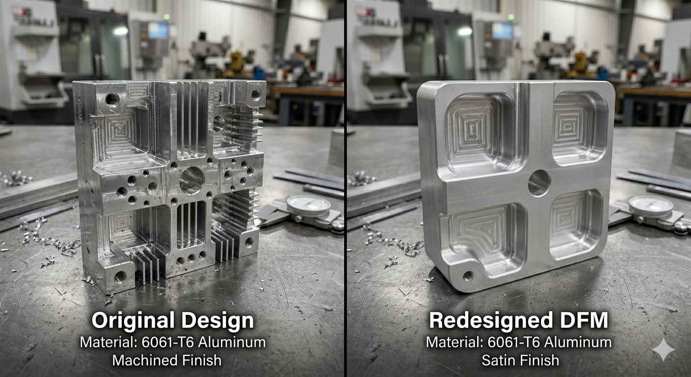
(AI generated) DFM redesign comparison for a 6061 aluminum machined part
In many CNC projects, simple DFM changes can reduce machining costs by 20%–50%.
Common examples include:
- Increasing internal corner radii
- Reducing unnecessary tight tolerances
- Using standard stock sizes
- Simplifying deep pocket geometries
JLCCNC engineers routinely identify these opportunities during DFM review before production begins.
Material Cost Reduction
Material selection is often the first major cost driver.
Engineers sometimes choose materials based purely on performance requirements without considering manufacturing impact.
In reality, material choice influences:
- Raw material cost
- Tool wear
- Machining speed
- Scrap rates
- Availability
- Lead time
A properly executed DFM design evaluates whether premium materials are truly necessary.
For example, in some applications, premium alloys may be specified even when lower-cost materials could satisfy the actual performance requirements.
The performance difference may be minimal.
The manufacturing cost difference can be enormous.
Good design for manufacturing guidelines encourage selecting the lowest-cost material capable of meeting design requirements.
That doesn't mean choosing cheap materials.
It means choosing appropriate materials.
Many cost-saving decisions happen long before production begins. For a deeper look at cost-focused engineering decisions, see our guide on Design for Cost (DFC) and how it complements DFM during product development.
Machining and Fabrication Cost Reduction
Manufacturing processes become expensive when geometry fights the process.
This is especially common in CNC machining.
Deep pockets.
Tiny internal radii.
Ultra-thin walls.
Excessively tight tolerances.
All of these increase production cost.
Effective DFM simplifies geometry wherever possible.
A corner radius increased from 1 mm to 3 mm may allow the use of a larger cutter.
That single change can dramatically reduce machining time.
Similarly, reducing unnecessary cosmetic features often lowers fabrication costs without affecting performance.
Strong design for manufacturability focuses on producing the required function with the simplest practical geometry.
That's one of the most powerful cost-reduction strategies available.
Setup and Tooling Cost Reduction
Many manufacturing costs occur before production even starts.
Fixtures must be built.
Programs must be created.
Tools must be selected.
Machines must be configured.
Every additional setup increases both cost and risk.
A good DFM design minimizes setup requirements whenever possible.
Features that can be machined in a single orientation are generally cheaper than features requiring multiple setups.
Similarly, designing around standard tooling often avoids custom tooling costs.
Experienced engineers frequently follow design for manufacturing guidelines that prioritize standard tools, standard stock sizes, and standard manufacturing practices because those choices consistently reduce production expenses.
Scrap and Rework Reduction
One defective part is expensive.
A hundred defective parts can destroy project profitability.
Scrap often originates from designs that push manufacturing processes beyond their practical limits.
Tight tolerances.
Fragile features.
Difficult assembly requirements.
Inconsistent process capability.
All contribute to yield loss.
A thorough DFM review identifies these risks before production begins.
That's why many manufacturers treat design for manufacturing as a quality initiative as much as a cost initiative.
Reducing scrap means:
- Lower material consumption
- Less machine time
- Fewer delays
- Better margins
The cost savings can be substantial, especially in high-volume production.
Lead Time Reduction
Lead time is often overlooked when discussing design for manufacturability, but it has a direct financial impact.
Complex parts typically require:
- More programming
- More setups
- More inspection
- More processing steps
Each additional step extends production schedules.
Good DFM design simplifies workflows.
Simpler workflows move through manufacturing faster.
Faster manufacturing improves delivery performance, inventory efficiency, and customer satisfaction.
In many cases, following proven design for manufacturing guidelines reduces lead time without changing product functionality at all.
The design still works exactly the same.
It simply becomes easier to manufacture.
And that's ultimately what DFM is all about.
A design that looks great in CAD can become expensive fast once it reaches production. A quick DFM review often reveals simpler ways to machine, bend, or manufacture the same part while reducing cost and lead time.
At JLCCNC, every quote includes a manufacturability review to help identify potential cost drivers before production begins.

Precision CNC Machining Service
Professional manufacturing, fast turnaround, and quality assurance.
Core Principles of Design for Manufacturing
The best design for manufacturing decisions usually happen before detailed CAD work begins. Many studies estimate that a large portion of a product's lifecycle cost is determined during the design phase, often cited in the range of 70–80%. That's why strong DFM practices focus on preventing problems rather than fixing them later.
Simplifying Part Geometry
Complex geometry almost always increases manufacturing cost.
Every pocket, contour, undercut, and custom feature adds machining time, programming effort, inspection requirements, or tooling challenges. A simple bracket may take 15 minutes to machine. A heavily optimized organic-shaped version might take over an hour while providing little additional value.
Good DFM design starts with a simple question: does this feature actually improve function?
If the answer is no, remove it.
Many successful design for manufacturing guidelines are surprisingly straightforward. Fewer features generally mean lower cost, shorter lead times, and more predictable quality.
Designing Around Process Capabilities
One of the most important design for manufacturability principles is designing for the process you're actually using.
A feature that's easy to produce in injection molding may be expensive in CNC machining. A geometry that's perfect for additive manufacturing may be impossible to form in sheet metal.
For example, most CNC shops prefer internal corner radii larger than the cutter diameter. Designing a 1 mm internal corner often requires smaller tools, longer cycle times, and higher costs.
Good DFM aligns product geometry with manufacturing capabilities instead of fighting them.
Every manufacturing process has physical constraints. Understanding common design limits in manufacturing helps prevent features that are difficult, expensive, or impossible to produce efficiently.
Standardizing Features and Materials
Every unique feature introduces variation.
Every unique material introduces supply chain complexity.
This is why mature manufacturing organizations standardize wherever possible.
Using common hole sizes, thread standards, stock material thicknesses, and established materials reduces procurement risk and production cost.
Strong DFM design focuses on repeatability. Standard parts are easier to source, easier to machine, and easier to inspect.
Eliminating Unnecessary Complexity
Engineers sometimes add complexity in pursuit of perfection.
Manufacturers usually pay for it.
A tolerance tighter than necessary. A cosmetic feature nobody sees. A custom thread that performs the same function as a standard one.
Each decision adds cost.
Effective design for manufacturing guidelines encourage engineers to challenge every feature and every requirement.
If it doesn't improve performance, reliability, or safety, it probably doesn't belong in the design.
DFM Considerations Across Manufacturing Processes
Good design for manufacturing looks different depending on the production method.
The same part may be excellent for one process and terrible for another.
CNC Machining
Although DFM principles apply across many manufacturing methods, CNC machining often provides the clearest examples because geometric decisions directly affect toolin and, setup count.
For CNC machining, DFM is largely about reducing unnecessary manufacturing effort. Parts do not become expensive simply because they are large. More often, cost comes from geometric features that restrict cutter access, increase cycle time, or force the machine shop into additional setups.
Several design characteristics frequently increase CNC machining cost:
- Deep pockets that require long-reach tools
- Internal corners smaller than standard cutter sizes
- Thin walls that deflect during cutting
- Tight tolerances applied to non-critical features
- Features that require multiple workholding orientations
For example, a pocket that is 50 mm deep but only 8 mm wide may require a long end mill with limited rigidity. Material removal rates decrease, tool deflection increases, and cycle time rises significantly. In many cases, slightly increasing pocket width or reducing depth can lower machining cost without affecting part function.
Wall thickness has a similar effect. Very thin walls can vibrate during machining and may deform after material removal. As wall thickness approaches 0.8 mm or below, manufacturability becomes increasingly material-dependent and may require special machining strategies. Plastic walls below approximately 1.5 mm become increasingly difficult to manufacture consistently.
Internal corner geometry is another common issue. CNC cutters are round, which means perfectly sharp internal corners cannot be produced directly. Increasing internal radii often allows larger cutters to be used, reducing machining time and improving tool life.
Tolerance selection also has a major influence on cost. Applying ±0.01 mm tolerances across an entire part increases inspection requirements and machining time. A more effective DFM approach is to reserve tighter tolerances only for features that directly affect fit, function, or assembly.
For additional recommendations covering wall thickness, hole depth, corner radii, thread design, and machining accessibility, see our CNC Machining Design Guidelines.
Sheet Metal Fabrication
In sheet metal fabrication, DFM centers on bend geometry, hole placement, and reducing unnecessary secondary operations. Parts designed around standard tooling are generally faster to produce and easier to control dimensionally.
Hole location is one of the issues that appears repeatedly during design reviews. A hole placed close to a bend line may stretch, distort, or shift slightly after forming. The drawing still looks correct, but fabrication often becomes less predictable. Moving the feature farther from the bend sometimes eliminates the problem entirely without changing how the part functions.
If you're designing bent sheet metal components, our detailed Sheet Metal Design Guidelines cover bend radii, hole placement, and other practical rules that improve manufacturability.
Injection Molding
Injection molding places heavy emphasis on draft angles, wall thickness consistency, rib design, and sink mark prevention. Because tooling investments are significant, geometry decisions made during design can affect production cost for the entire life of the mold.
Wall thickness is often where problems begin. Designers sometimes add material to increase stiffness. In practice, thick sections cool more slowly than surrounding regions. The result may be visible sink marks on cosmetic surfaces or warpage after ejection. Many molded housings achieve better dimensional stability by using ribs to support the structure rather than increasing wall thickness throughout the part.
Die Casting
Die casting follows many of the same DFM principles found in injection molding. Draft remains important, but wall-section control usually has a greater influence on casting quality.
Large changes in wall thickness can create localized hot spots inside the casting. Those regions solidify later than surrounding material and are more susceptible to shrinkage porosity. Engineers frequently adjust rib layouts or redistribute material to keep sections more uniform. The external geometry may remain almost unchanged while casting yield improves noticeably.
Additive Manufacturing (3D Printing)
Additive manufacturing changes some traditional DFM assumptions. Geometry that would be difficult to machine may be straightforward to print. At the same time, build orientation starts to influence cost, build time, and post-processing effort.
Support generation is a typical example. A bracket with large horizontal overhangs may print successfully, but support structures can consume substantial material and require additional finishing afterward. Rotating the part or modifying a few surfaces often reduces support volume considerably. The geometry changes very little. The production workflow changes quite a lot.
Material Selection in DFM
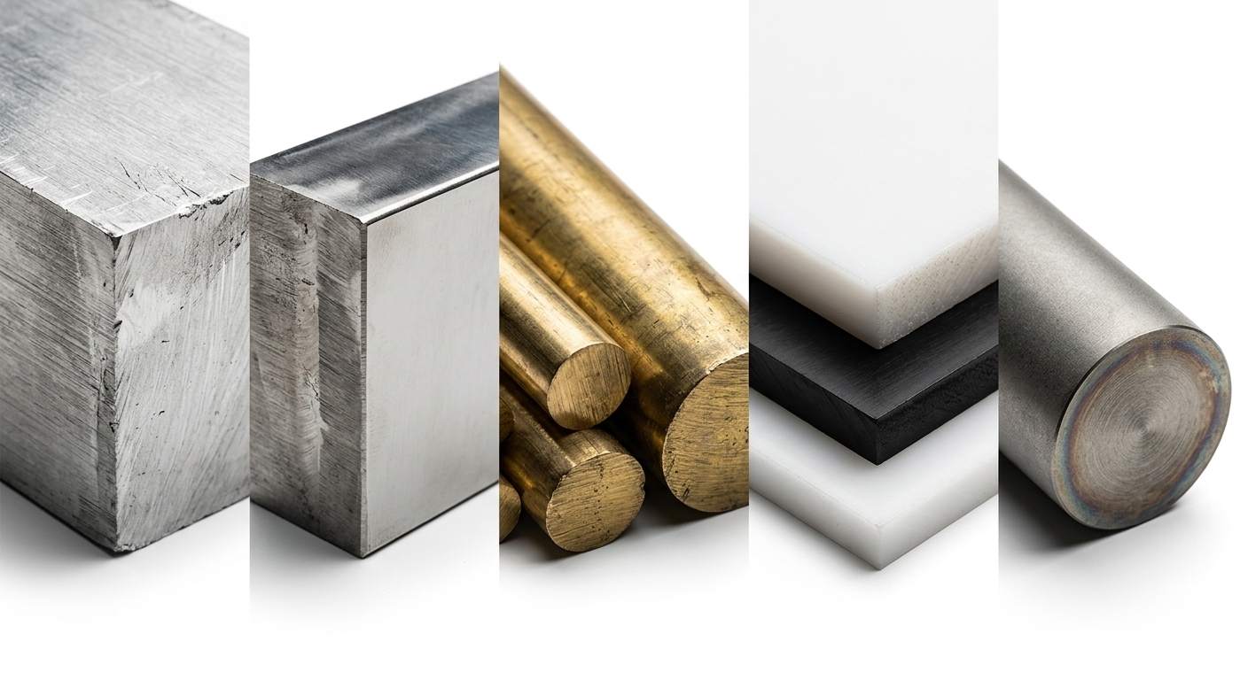
(AI generated) Various engineering materials used for manufacturing
Material selection affects far more than performance.
The material chosen during DFM influences machining speed, tool wear, lead time, sourcing risk, and final part cost.
In many cases, the material decision has a larger impact on cost than the geometry itself.
Material Availability
The best material on paper isn't always the best material in production.
Aluminum 6061, for example, is available globally and stocked by virtually every machine shop. Specialty aerospace alloys may require weeks of sourcing.
A good design for manufacturability review considers supply chain realities alongside engineering requirements.
Choosing readily available materials often shortens lead times dramatically.
Machinability and Formability
Some materials are simply easier to process than others.
6061 aluminum machines roughly three to five times faster than titanium. Stainless steel typically requires slower feeds, generates more heat, and increases tool wear.
The same concept applies to sheet metal fabrication. Softer materials generally bend more predictably and require less forming force.
Effective DFM balances material performance with manufacturing efficiency.
Performance vs Manufacturing Cost
Not every application requires the highest-performing material available.
Using titanium for a non-structural enclosure may double or triple manufacturing cost without providing meaningful benefits.
One of the core goals of DFM design is matching material capability to actual functional requirements.
The cheapest material isn't always correct.
The most expensive material usually isn't either.
Common Design Features That Increase Manufacturing Cost
Certain design choices appear repeatedly during DFM reviews because they add manufacturing complexity without improving part performance.
| Design Feature | Why It Increases Cost | Better DFM Approach |
|---|---|---|
| Excessively tight tolerances | Requires slower machining, additional inspection, specialized setups, and higher scrap risk. A ±0.005 mm tolerance is significantly more expensive than ±0.05 mm. | Apply tight tolerances only to functional features that truly require precision. |
| Deep cavities and limited tool access | Requires long cutting tools that deflect more, vibrate more, and remove material more slowly. | Keep pocket depth reasonable and maintain good tool accessibility whenever possible. |
| Thin walls and fragile features | Walls can flex during machining, distort during fabrication, and increase scrap rates. | Maintain adequate wall thickness based on material and manufacturing process. |
| Multiple setups and complex geometry | Every setup adds labor, inspection time, fixture requirements, and positioning variation. | Design parts to be machined or fabricated in as few setups as possible. |
| Custom feature sizes | May require non-standard tooling, special fixtures, or additional programming. | Use standard hole sizes, thread sizes, radii, and stock dimensions. |
| Unnecessary cosmetic details | Adds machine time and complexity without improving functionality. | Remove features that do not contribute to performance, assembly, or aesthetics. |
Conclusion About Design for Manufacturing
Products that move smoothly into production are usually designed with manufacturing constraints in mind from the beginning. Small decisions made during design can eliminate extra setups, reduce material waste, shorten lead times, and significantly lower production costs.
A good DFM process helps engineers avoid expensive surprises later by identifying manufacturing challenges while they're still easy to fix.
At JLCCNC, manufacturability is reviewed before production starts, helping engineers optimize designs for CNC machining, sheet metal fabrication, injection molding, and additive manufacturing. Whether you're building a prototype or preparing for production, early DFM feedback can reduce cost and improve outcomes before a single part is made.
Ready to validate your design? Upload your CAD file to JLCCNC and receive an instant quote with expert DFM feedback.
Precision CNC Machining Service
Professional manufacturing, fast turnaround, and quality assurance.
FAQ About Design for Manufacturing
Q: What is design for manufacturing?
Design for manufacturing (DFM) is the process of designing products so they can be manufactured more easily, consistently, and cost-effectively while meeting performance requirements.
Q: What is the difference between DFM and DFA?
DFM focuses on making individual parts easier to manufacture, while DFA (Design for Assembly) focuses on making products easier and faster to assemble.
Q: Why is DFM important in manufacturing?
DFM helps reduce production cost, improve quality, shorten lead times, reduce manufacturing risk, and prevent expensive design changes later in the product lifecycle.
Q: How does DFM reduce manufacturing cost?
DFM reduces cost by simplifying geometry, reducing setups, minimizing waste, improving process efficiency, selecting appropriate materials, and avoiding unnecessary manufacturing complexity.
Q: What are common DFM guidelines for CNC machining?
Common CNC machining DFM guidelines include using realistic tolerances, maintaining proper wall thicknesses, avoiding deep narrow pockets, increasing internal corner radii, and minimizing setup requirements.
Q: What are common DFM guidelines for sheet metal fabrication?
Common sheet metal DFM guidelines include using appropriate bend radii, maintaining proper hole-to-edge distances, incorporating bend relief features, and reducing secondary operations whenever possible.
Q: When should a DFM review be performed?
A DFM review should be performed as early as possible during product development, ideally before prototypes, tooling, or production planning begin.
Q: What are the main principles of DFM?
The main principles of DFM include simplifying geometry, designing around manufacturing process capabilities, standardizing materials and features, reducing production complexity, and minimizing manufacturing cost without compromising product performance.
Keep Learning
Counterbore Holes: Symbols, Callouts, Dimensions & Applications
Key Takeaways A counterbore provides extra space above a hole so the fastener head does not project above the part surface. Socket head cap screws are commonly installed in counterbore holes because the recess matches the shape of the screw head. Three dimensions define the feature: the hole size, the recess diameter, and the recess depth. The hole and the recess are machined on the same centerline to maintain proper alignment between the hole and the recessed seating surface. In most applications, th......
Differences Between Tolerance and Allowance
Key Takeaways Tolerance controls the allowable variation of a single dimension, while allowance is the intentional difference between two mating parts that determines the type of fit. Tolerance and allowance are closely related but describe different aspects of dimensional control. Tolerance defines the acceptable variation of a single dimension, while allowance defines the intentional difference between mating parts to achieve a required fit. Confuse them and you end up with parts that either won't a......
Types of Holes in Engineering: Design, Symbols, and Manufacturing Guide
Types of holes in engineering - illustration (Erye rubber & plastic parts) Key Takeaways Engineering holes are used to support fastening, alignment, bearing installation, fluid flow, and other functional requirements. The main types of holes include through holes, blind holes, threaded holes, counterbore holes, countersink holes , spotface holes, screw clearance holes, reamed holes, and dowel holes. Hole geometry determines the required machining process. Some holes only require CNC drilling , while o......
True Position in GD&T: Symbol, Formula, Tolerance, and Manufacturing Applications
Key Takeaways About True Position True position defines the allowable variation in a feature's location from its basic dimensions. The control applies to holes, slots, pins, threaded features, and datum features. A circular tolerance zone controls features in 2D, while a cylindrical zone controls feature axes in 3D. Datum references establish the coordinate system used for manufacturing and inspection. Maximum Material Condition (MMC) adds bonus tolerance as the feature departs from its maximum materi......
Tolerance Stack-Up: Analysis, Examples, and How It Affects Manufacturing and Assembly
Key Takeaways About Tolerance Stack-Up Tolerance stack-up determines the dimensional variation that accumulates across multiple features and assembled parts. The stack-up study allows engineers to identify gaps, interference issues, alignment shifts, and fit conditions before production starts. Small dimensional variations from several parts can combine and create larger assembly issues. Usually, worst-case analysis evaluates the maximum possible variation by combining all tolerance limits. Statistica......
How to Read Engineering Drawings: Symbols, Dimensions, and Practical Interpretation
Key Takeaways About Engineering Drawings Engineering drawings communicate product requirements throughout manufacturing, inspection, assembly, and quality control. They communicate information that may not be fully defined in a CAD model, such as allowable variation, surface requirements, and inspection points. A drawing review starts with understanding the part reference system. The machinist checks which surfaces are used as datums, how features relate to each other, and which areas need access duri......