Types of Holes in Engineering: Design, Symbols, and Manufacturing Guide
19 min
- What Are Holes in Engineering?
- Common Types of Holes in Engineering
- Hole Symbols and Callouts in Engineering Drawings
- Choosing the Right Hole Type
- Design Considerations for CNC-Machined Holes
- How Different Hole Types Are Manufactured
- Common Engineering Functions of Hole Types
- FAQ about Types of Holes in Engineering
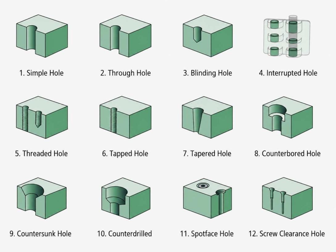
Types of holes in engineering - illustration (Erye rubber & plastic parts)
Key Takeaways
- Engineering holes are used to support fastening, alignment, bearing installation, fluid flow, and other functional requirements.
- The main types of holes include through holes, blind holes, threaded holes, counterbore holes, countersink holes , spotface holes, screw clearance holes, reamed holes, and dowel holes.
- Hole geometry determines the required machining process. Some holes only require CNC drilling , while others may require additional operations such as reaming, boring, tapping, or thread milling.
- Engineering drawings define the complete hole specification, including size, depth, threads, tolerances, surface finish, and GD&T requirements.
- Reviewing hole requirements during process planning helps select suitable tooling and avoids unnecessary machining operations.
Holes are found on almost every machined component. However, they are often the features that control how a part functions after assembly. Fasteners, bearings, dowel pins, shafts, and sealing elements all depend on the hole being produced to the dimensions shown on the drawing.
Not every engineering hole is manufactured in the same way. A simple clearance hole may only require drilling, while a bearing seat or locating hole often needs additional finishing to achieve the specified size and surface condition. The selected machining process depends on the:
- Feature geometry
- Tolerance
- Intended application
Engineering drawings provide the information needed to manufacture these features correctly. Besides diameter, they define:
- Thread details
- Depth
- Counterbores
- Countersinks
- Tolerances
Geometric controls that influence machining and inspection.
This guide explains:
- How engineering holes are used in machined parts
- The common hole features found on technical drawings, their callouts, and geometries
- The machining operations used to produce them
What Are Holes in Engineering?
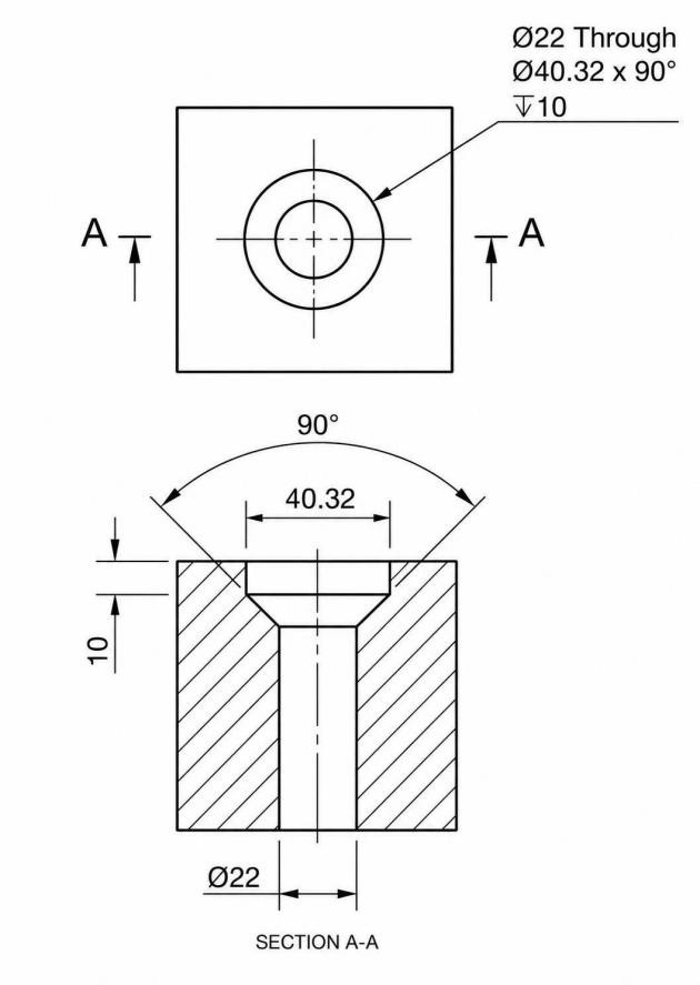
An illustration of a hole
An engineering hole is a machined feature produced to perform a specific function within a component. The feature is designed around assembly requirements, moving parts, fastening methods, or fluid flow rather than simply removing material from the workpiece.
A single part may contain several hole types because each feature performs a different task. Some provide clearance for fasteners, some locate mating components, while others support bearings or contain internal threads.
Although these features share a circular shape, their dimensions, tolerances, and machining methods often differ.
Typical engineering hole applications include:
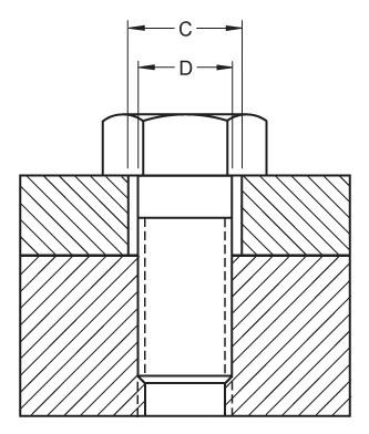
Bolt and Screw Clearances - Engineering Essentials
- Clearance holes for bolts and screws
- Threaded holes for direct fastening
- Bearing and bushing seats
- Dowel holes for component alignment
- Passages for coolant, lubrication, compressed air, and hydraulic fluid
Standard drilling produces many holes, while tighter tolerances and functional surfaces usually require additional machining before the part is inspected.
Features Commonly Added to Engineering Holes
Many engineering holes include secondary features that support assembly, fastening, or dimensional control. These features are specified on the drawing and are machined after the initial drilling operation.
Internal Threads: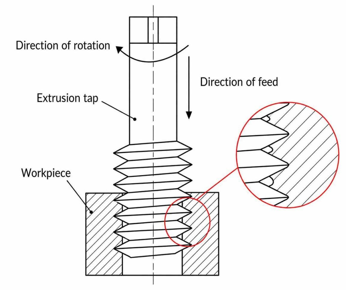
Internal threads - ResearchGate
Internal threads allow bolts and screws to engage directly with the workpiece. After the hole is drilled to the correct tap size, the thread is produced by tapping or thread milling according to the drawing specification.Counterbores: A counterbore creates a larger cylindrical recess above the main hole. This recess provides space for bolt heads and socket head cap screws that need to sit below the surrounding surface.
Countersinks: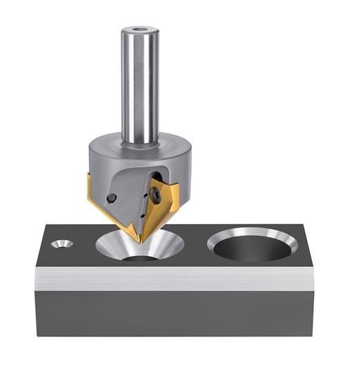
Countersinks - Canadian Metalworking
A countersink forms a conical opening that matches the head angle of a flat-head screw. The fastener seats against this surface during assembly and finishes flush with the component.Spotfaces: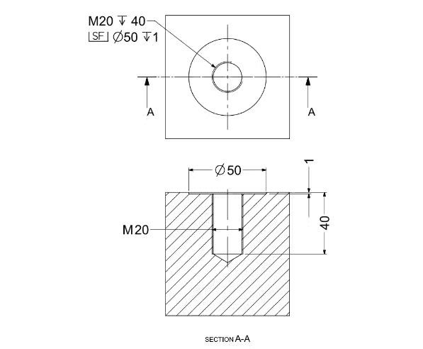
Spotface - CNC Cookbook
A spotface removes a small amount of material around a hole. So, it produces a flat seating surface. This feature is commonly used in castings and forged parts because the original surface is not suitable for direct fastening.Reamed Holes: Reaming is carried out after drilling when the specified hole size cannot be achieved by drilling alone. It only removes a small amount of material from the existing hole to produce the required diameter and surface condition.
Blind Hole Depth: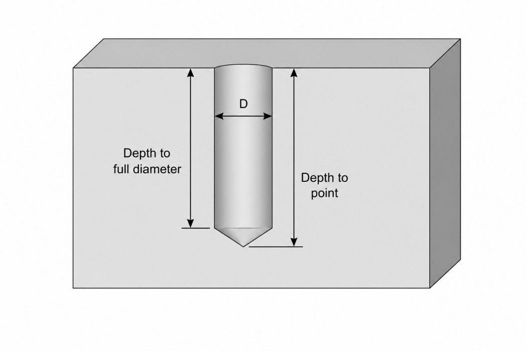
Blind hole depth - (DEK)
Blind holes terminate within the material instead of passing completely through the component. The specified depth must provide enough space for the mating part while maintaining the remaining wall thickness shown on the design.Chamfers: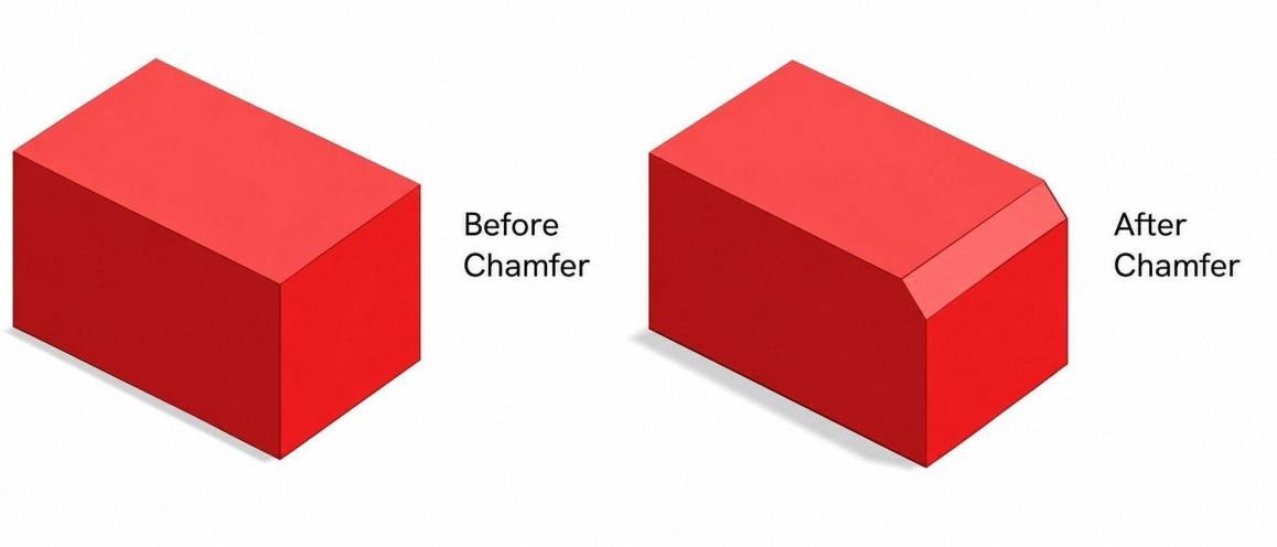
Chamfer Edge - Colstan Profiles
Chamfers are machined around the hole entrance to remove sharp edges and prepare the feature for assembly. They also help guide fasteners into the hole during installation.Dimensional and Positional Tolerances: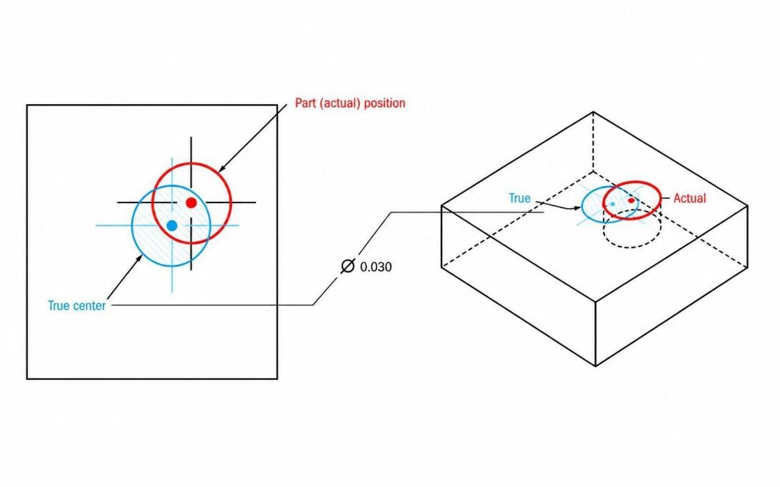
True Position GD&T-Position Tolerance - ECOREPRAP
Hole size alone does not define the finished feature. Engineering drawings may also control location, orientation, concentricity, perpendicularity, and true position through dimensional tolerances and GD&T requirements.Common Types of Holes in Engineering
Engineering drawings include several hole types because each one supports a specific mechanical function.
The table below summarizes the hole types most frequently specified in mechanical design and CNC machining .
| Hole Type | Drawing Symbol / Callout | Primary Purpose | Typical Manufacturing Method | Typical Application |
|---|---|---|---|---|
| Through Hole | ⌀10 THRU | Passes completely through the workpiece | Drilling | Clearance holes, fluid passages |
| Blind Hole | ⌀10 × 15 DEEP | Stops at a specified depth | Drilling, boring | Thread preparation, bearing pockets |
| Threaded (Tapped) Hole | M8 × 1.25-6H | Creates internal threads | Drilling, tapping, and thread milling | Mechanical assemblies |
| Counterbore Hole | ⌴ ⌀18 × 8 | Recessed cylindrical fastener heads | Drilling, counterboring | Socket head cap screws |
| Countersink Hole | ⌵ ⌀20 × 90° | Seats flat head screws | Drilling, countersinking | Flush fastener installation |
| Spotface Hole | ⌴ SF ⌀20 | Produces a flat seating surface | Spotfacing | Bolt heads, washers |
| Screw Clearance Hole | ⌀8.5 CLR | Allows fasteners to pass freely | Drilling | Bolted joints |
| Reamed Hole | ⌀10 H7 | Produces an accurate hole size | Drilling, reaming | Bushings, precision fits |
| Dowel Hole | ⌀8 H7 | Locates mating components | Drilling, reaming | Precision assemblies |
1. Through Holes
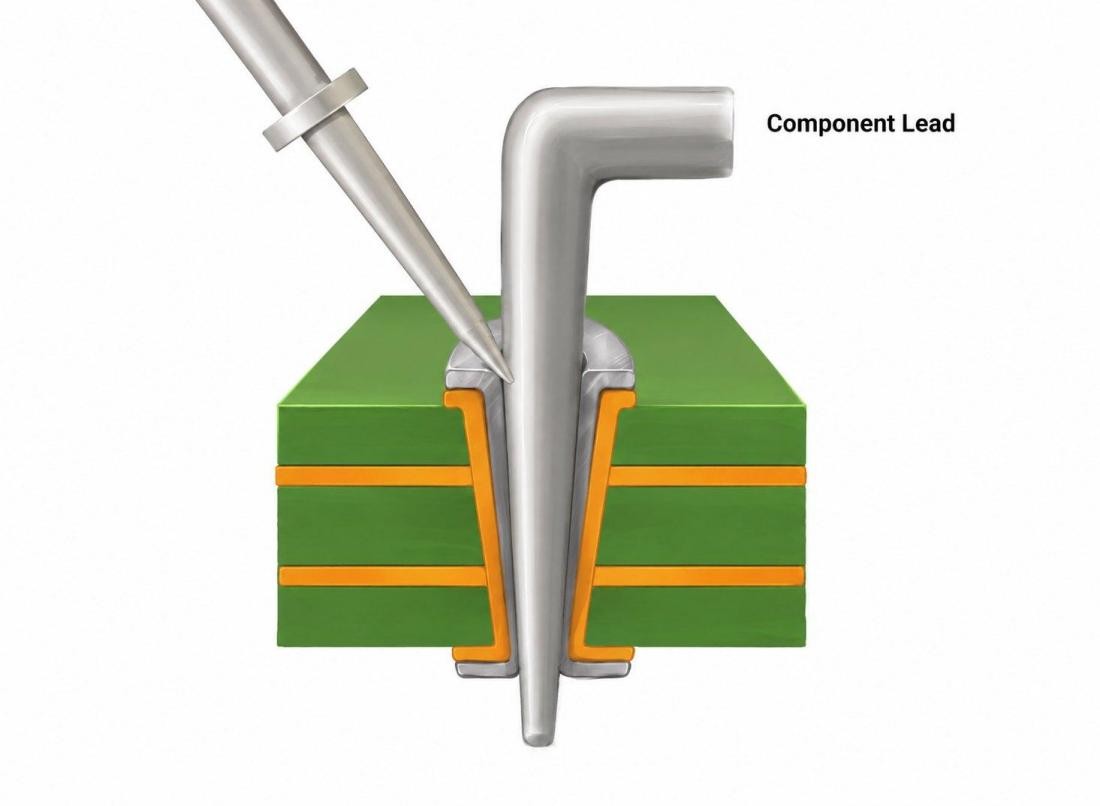
Through holes create an open passage across the full thickness of a component. They are commonly specified for bolted joints, locating pins, cable routing, and internal flow passages.
Since the drill breaks through the opposite face, chips leave the cutting zone more easily than in a blind hole . Most through-holes are produced by drilling. Although precision features may require reaming and boring before inspection.
2. Blind Holes
Blind holes terminate within the material and do not open on the opposite face. They are often specified where the external surface must remain continuous or where a component needs a controlled installation depth. During machining, the drill point leaves a tapered bottom that reduces the usable depth inside the hole. Drawings that require a flat bottom usually call for an additional machining operation.
3. Threaded Holes
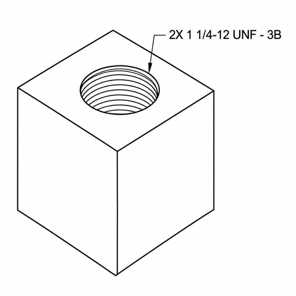
Threaded Hole - Accurate Machine Products
Threaded holes provide an internal thread for screws and bolts without using a separate nut. The hole is first drilled to the correct tap size, then the thread is produced according to the specified standard.
Tapping is primarily used for standard thread sizes, while thread milling offers better control in larger threads, harder materials, and precision applications.
4. Counterbore Holes
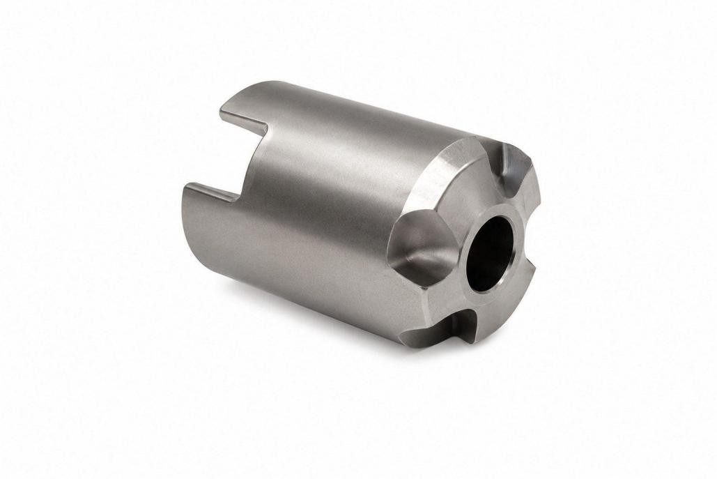
Counterbore - MSC Direct
Counterbores provide a recessed seat for socket head cap screws and similar fasteners. The larger diameter is machined above the main hole so the fastener head sits below the component surface after assembly. Both diameters share the same centerline to maintain proper alignment during installation.
5. Countersink Holes
Countersinks are machined for flat-head screws that must finish flush with the surrounding surface. The conical seat is produced at the angle specified for the selected fastener. Incorrect countersink geometry reduces the contact area between the screw head and the component.
6. Spotface Holes
Spotfaces create a flat seating surface around a hole without machining the entire face of the workpiece. They are frequently added to castings, forgings, and welded fabrications where the original surface is uneven. The machined area provides a stable contact surface for bolt heads, washers, and nuts.
7. Screw Clearance Holes
Clearance holes allow a fastener to pass through one component without engaging the material. The clamping force comes from threads located in another component or from a nut fitted during assembly. Hole diameter is selected according to the specified clearance class and assembly requirements.
8. Reamed Holes
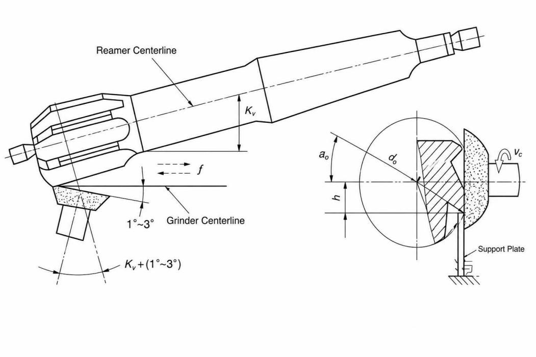
Reamed Holes - Ultirapid Manufacturing
Reamed holes are specified when drilling cannot produce the required dimensional accuracy. Reaming removes a small amount of material from a pre-drilled hole. This brings it to the final size defined on the engineering drawing. It also improves roundness and surface finish compared with drilling alone.
9. Dowel Holes
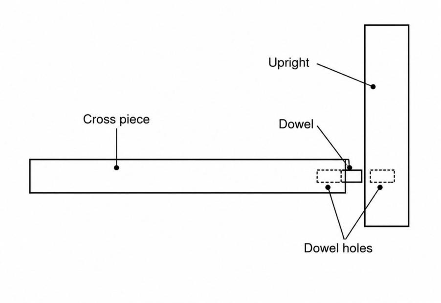
Dowel holes - Home improvement stack exchange
Dowel holes establish the position of mating components during assembly. They are normally drilled first and then reamed to the final diameter so the required fit can be achieved. In addition to hole size, the drawing also controls hole location because positional error directly affects assembly alignment.
Hole Symbols and Callouts in Engineering Drawings
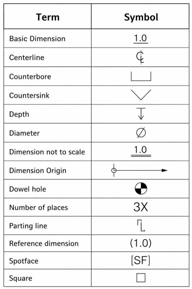
Hole Symbols and Callouts
Engineering drawings communicate far more than hole diameter. A complete hole callout defines the feature size, depth, thread specification, tolerance, and any secondary machining required before the part reaches inspection. Standard symbols allow machinists, programmers, and inspectors to interpret the drawing consistently across different manufacturing environments.
Common Hole Symbols
The symbols below appear frequently on mechanical drawings and CAD models.
| Symbol | Meaning | Typical Example |
|---|---|---|
| ⌀ | Hole diameter | ⌀12 |
| THRU | Hole passes through the entire part | ⌀10 THRU |
| DEEP | Blind hole depth | ⌀12 × 20 DEEP |
| ⌴ | Counterbore | ⌴ ⌀18 × 8 |
| ⌵ | Countersink | ⌵ ⌀20 × 90° |
| M | Metric thread | M10 × 1.5 |
| UNC / UNF | Unified thread designation | 1/4-20 UNC |
| H7 | Hole tolerance class | ⌀10 H7 |
Drawing standards may vary between ISO, ASME, and company documentation, though the function of each symbol remains consistent. Standard callouts reduce interpretation errors during programming, machining, and inspection.
Reading Hole Callouts
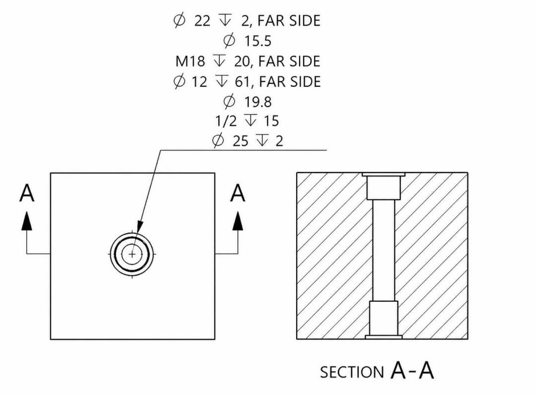
Advanced hole callout - Innova Systems
A hole callout combines multiple specifications into a single note. Diameter usually appears first, followed by depth, thread designation, tolerance class, and secondary features such as counterbores and countersinks.
For example, the callout ⌀10 THRU identifies a through hole with a finished diameter of 10 mm. A note such as M8 × 1.25-6H specifies a metric internal thread together with its thread class. Counterbore and countersink dimensions are normally added within the same callout, so every machining operation remains linked to a single feature.
Inspection personnel also reference these callouts while verifying the finished component. Diameter, thread quality, feature depth, and geometric tolerances are checked against the information shown on the drawing rather than the CAD model alone.
CAD Hole Marking Conventions
Modern CAD systems generate hole callouts automatically from the feature definition stored in the model. Hole Wizard features, threaded hole libraries, and standard fastener databases apply the correct symbols and dimensions while maintaining consistency across engineering drawings.
Once the model reaches CAM programming, the same feature data helps identify drilling, tapping, reaming, counterboring, and countersinking operations. Maintaining standard hole definitions throughout design and manufacturing reduces drawing revisions, programming changes, and inspection discrepancies during production.
Choosing the Right Hole Type
Hole selection reflects the function of the component, the assembly method, and the manufacturing process. A feature that performs well during assembly should also support practical machining and straightforward inspection. For this reason, engineers define hole geometry along with tolerances, fastener specifications, and production requirements rather than treating the hole as an isolated feature.
Functional Requirements
Locating features commonly use reamed holes because dowel pins rely on controlled diameter and positional accuracy to maintain assembly alignment.
Bearing housings frequently require bored holes to achieve the diameter, roundness, and surface finish needed for proper bearing installation.
Clearance holes, threaded holes, hydraulic ports, and lubrication passages each satisfy distinct functional requirements, necessitating different machining operations and dimensional controls.
Assembly and Fastener Requirements
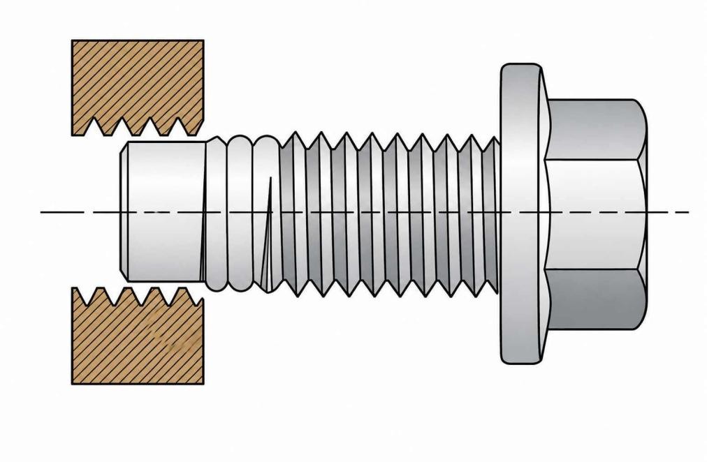
Fastener solves assembly problems and creates sustained savings - PressBox
Fastener style determines the required hole feature. Socket head cap screws generally pair with counterbores, while flat head screws seat against countersinks machined to the specified angle.
Multi-part assemblies typically combine clearance holes with threaded holes so the fastener clamps the components together without binding during installation.
Hole location influences assembly quality as much as hole size. Even a correctly machined diameter cannot compensate for poor positional accuracy in locating features.
Manufacturing Cost and Machinability
Standard drilled holes require fewer machining operations than threaded, reamed, counterbored, and bored features, reducing machining time and tooling cost.
Deep blind holes place greater demands on chip evacuation, coolant delivery, and tool stability, particularly in harder engineering materials.
Standard drill diameters, thread sizes, and counterbore dimensions simplify programming, tooling, inspection, and repeat production.
Inspection and Maintenance Considerations
Inspection commonly focuses on diameter, position, depth, perpendicularity, and thread quality because each characteristic influences assembly performance.
Locating holes and bearing seats generally receive tighter dimensional verification than non-critical clearance holes due to their influence on component alignment.
Standardized hole dimensions simplify maintenance by allowing replacement fasteners, gauges, and inspection equipment to be used without special tooling.
Choosing the correct hole type is only part of a manufacturable design. Hole depth, tolerance, thread specification, and surrounding geometry can all affect how the feature is machined. Before production, JLCCNC reviews engineering drawings to identify potential manufacturability issues and recommend practical machining approaches.
Upload your CAD file to receive a quotation and an engineering review before machining begins.

Precision CNC Machining Service
Professional manufacturing, fast turnaround, and quality assurance.
Design Considerations for CNC-Machined Holes
Hole dimensions influence much more than the finished drawing. Tool selection, machining sequence, inspection, and assembly are all affected by the way a hole is specified during the design stage.
Hole Depth-to-Diameter Ratio
Hole depth determines the drilling strategy. Shallow holes are commonly completed in a single cycle, while deeper features often require peck drilling to clear chips before they compact inside the flute.
Blind holes require additional depth below the specified thread because the drill point and tap cannot produce full threads to the bottom of the hole.
Deep holes also increase tool deflection, making diameter variation more noticeable than in shorter drilling operations.
Hole Spacing and Edge Distance
Hole patterns positioned close together reduce the material supporting each feature, which becomes more noticeable in aluminum, plastics, and thin-wall components.
Counterbores and countersinks remove additional material around the hole entrance, requiring more surrounding stock than a simple drilled hole.
Inspection probes, drill bodies, and tapping heads also require working space around closely grouped hole patterns.
Standard Sizes and Tool Availability
Hole diameters matching standard drill sizes usually move directly from programming to production without additional machining operations.
Fractional, metric, and letter drill sizes are commonly stocked, while intermediate diameters often require boring heads, end mill interpolation, or dedicated tooling.
Standard thread series such as M6 × 1, M8 × 1.25, and 1/4-20 UNC also reduce tooling changes during production.
Tolerance and Inspection Planning
A clearance hole rarely receives the same inspection as a dowel hole because both features perform different functions after assembly.
Hole location is frequently verified together with diameter, particularly for dowel pins, bearing seats, and multi-hole bolt patterns.
Tight positional requirements often increase inspection time because CMM verification becomes more practical than manual measurement for complex components.
How Different Hole Types Are Manufactured
Drilling and Reaming
Drilling is the first operation for most engineering holes because it establishes the initial diameter and hole location.
Standard clearance holes are often completed after drilling if no additional accuracy is required.
Reaming is used when the drawing specifies a tighter hole tolerance or improved surface finish.
The drilled hole is left slightly undersized so the reamer can remove a small amount of material and produce the final diameter.
Counterboring, Countersinking, and Spotfacing
Counterboring creates a flat-bottom recess for socket head cap screws and similar fasteners.
Countersinking machines have a conical seat that matches the angle of a flat-head screw.
Spotfacing produces a flat seating surface around a hole on cast, forged, or welded components.
These operations modify an existing hole to meet assembly requirements without changing its primary function.
Thread Creation Methods
Threaded holes begin with a pilot hole drilled to the correct tap size.
Tapping is commonly used for standard metric and Unified threads in general production.
Thread milling is selected for larger threads, hard materials, deep holes, and parts that require better thread accuracy.
The machining method depends on the thread specification, workpiece material, and production requirements.
Secondary Finishing Operations
Chamfers remove sharp edges from the hole entrance and improve assembly.
Deburring removes material left after drilling and prevents interference during installation.
Boring corrects hole size, straightness, and concentricity before the final finishing operation.
Honing is used on selected holes where a fine surface finish and accurate geometry are required, such as bearing bores and hydraulic components.
Common Engineering Functions of Hole Types
Hole features perform specific tasks after machining is complete. Their purpose extends beyond material removal because they influence assembly, component location, fluid distribution, and structural design throughout the product's service life.
Fastening and Assembly
Machine bases, covers, brackets, and gearbox housings commonly combine threaded holes with clearance holes so adjoining components can be clamped together with standard fasteners.
Counterbores appear frequently around socket head cap screws because the fastener head must remain below the surrounding surface after assembly.
Countersinks are widely specified on covers, panels, and sheet metal parts that require a flush fastener profile.
Precision Positioning and Alignment
Dowel holes establish the reference position between two mating components before bolts apply the clamping force.
Bearing housings, fixture plates, mold bases, and indexing fixtures commonly contain reamed holes because positional accuracy influences the entire assembly.
Many precision assemblies separate locating holes from fastening holes so each feature performs a single function during installation.
Fluid and Process Passages
Hydraulic manifolds contain intersecting drilled holes that create internal oil passages without increasing the number of manufactured components.
Cooling channels inside molds and dies rely on drilled passages that circulate coolant close to heat-producing regions of the tool.
Pneumatic valves, pump bodies, and instrumentation blocks also incorporate threaded ports for fittings, plugs, pressure sensors, and gauges.
Functional and Weight-Reduction Features
Structural brackets and aerospace components often include circular lightning holes to reduce part weight while maintaining the surrounding load path.
Access holes provide clearance for sockets, hex keys, adjustment tools, inspection probes, and maintenance equipment after installation.
Drain holes and vent holes prevent coolant, oil, cleaning fluids, and trapped air from remaining inside enclosed cavities during operation.
FAQ about Types of Holes in Engineering
Q: What are the main types of holes in engineering?
The most common hole types in mechanical engineering include through holes, blind holes, threaded (tapped) holes, clearance holes, counterbored holes, countersunk holes, spotfaced holes, reamed holes, and dowel holes.
Q: What is the difference between a through hole and a blind hole?
A through hole passes completely through the workpiece, allowing access from both sides. A blind hole stops at a specified depth and does not break through the opposite surface. Blind holes are commonly specified for threaded features, while through holes frequently serve as clearance holes and fluid passages.
Q: What is the difference between a counterbore and a countersink?
A counterbore produces a flat-bottom cylindrical recess that accommodates socket head cap screws and similar fasteners. A countersink machines a conical recess that allows flat-head screws to sit flush with the component surface.
Q: What is a hole callout?
A hole callout is the drawing note that defines every machining requirement for a hole. It may include the diameter, depth, thread specification, tolerance class, counterbore, countersink, and additional manufacturing information required to produce the feature correctly.
Q: What is CAD hole marking?
CAD hole marking is the automatic generation of hole callouts from features created in CAD software. The software carries hole size, depth, thread information, and secondary machining details directly to the engineering drawing.
Q: What do hole symbols mean on engineering drawings?
Hole symbols provide a standardized method of describing hole features. Common examples include ⌀ for diameter, ⌴ for counterbores, ⌵ for countersinks, THRU for through holes, and thread designations such as M10 × 1.5 for metric threads.
Q: Which hole types are easiest to machine?
Standard drilled holes, including many through holes and clearance holes, generally require the fewest machining operations because they are often completed with a drilling cycle. Reamed, threaded, counterbored, and countersunk holes may require additional machining steps, increasing production time.
Q: How do hole types affect CNC machining cost?
Hole design influences machining time, tooling, and inspection. Standard drilled holes generally cost less to produce, while threaded, reamed, bored, and deep blind holes increase machining operations, tool wear, and inspection requirements.
Q: What is the difference between a drilled hole and a reamed hole?
A drilled hole is produced directly by a drill bit and is suitable for general-purpose applications. A reamed hole is finished with a reamer after drilling to achieve tighter diameter tolerances, improved roundness, and a smoother surface finish, making it suitable for precision locating features such as dowel holes.
Precision CNC Machining Service
Professional manufacturing, fast turnaround, and quality assurance.
Conclusion About Types of Holes in Engineering
Engineering holes serve far more purposes than simply providing a drilled opening. Each hole type is designed for a specific engineering purpose, and that purpose determines how the feature is manufactured, inspected, and used during assembly. The selected hole geometry also influences machining operations, inspection methods, assembly procedures, and production cost.
Understanding the differences between through holes, blind holes, threaded holes, counterbores, countersinks, reamed holes, and other common features helps engineers produce drawings that are easier to manufacture and inspect. Standard hole callouts, practical tolerances, and widely available tooling further simplify CNC production while reducing unnecessary machining operations.
Before machining begins, hole specifications are typically reviewed alongside material, tolerances, and assembly requirements to confirm that the selected manufacturing process is appropriate. JLCCNC reviews engineering drawings before production to identify potential manufacturability issues and recommend suitable machining approaches. Upload your CAD file to receive a quotation and DFM review for your project.
Keep Learning
Circularity GD&T Explained
Key Takeaways Circularity controls how round each cross-section is on a cylindrical, conical, or spherical surface. Each cross-section is checked separately. Circularity doesn't control taper, axis straightness, or alignment between sections. No datum is needed because circularity controls the shape of the feature itself. The circularity tolerance zone is bounded by two concentric circles whose radial separation equals the specified tolerance. Each circular element must fit within its own zone, evalua......
Press Fit Tolerance: Interference, Charts & Design Guide
Key Takeaways A press fit is an interference fit: the shaft is larger than the hole, and elastic deformation of the mating parts after assembly creates contact pressure that generates the friction holding the joint together. Press fit interference is the difference between the shaft diameter and the hole diameter. Minimum interference uses worst-case dimensions for the smallest overlap. Maximum interference uses worst-case dimensions for the largest overlap. Press fit tolerance is selected based on re......
GD&T Datum: Definition, Types, Symbols, and Datum Reference Frame
Key Takeaways A datum in GD&T is a theoretically exact reference used to locate or orient other features on a part. It is not the physical surface itself. A datum feature is the physical feature identified on the part and used to establish a datum. The datum itself is the theoretically exact geometric reference derived from that feature. Datums become especially important when several features have to work together. A hole pattern, bearing bore, mounting face, or mating surface may need to establish t......
GD&T Runout: Definition, Symbol, Measurement & Tolerance
Key Takeaways Runout limits surface variation while a part rotates around its specified datum axis. The datum feature establishes the axis used for the runout requirement. You compare the full indicator variation during rotation with the tolerance stated on the drawing. Circular runout applies at individual circular sections of the controlled surface. Total runout evaluates the controlled surface across its specified extent. Runout is not a size tolerance, and its value is not determined by the diamet......
GD&T Perpendicularity: Definition, Tolerance & Examples
Key Takeaways Perpendicularity is an orientation control used for a feature specified at 90° to a datum. A surface callout controls the complete surface within two parallel planes set perpendicular to the referenced datum. An axis callout controls the derived axis inside the specified tolerance zone instead of controlling the physical surface directly. Perpendicularity does not establish the location of a feature. A drawing can require another geometric control when position also needs definition. Dat......
Concentricity in GD&T: Definition, Symbol, Tolerance, and Measurement
Key Takeaways Concentricity in legacy ASME GD&T controls the derived median points of a feature relative to a datum axis. It does not simply compare the axes of two fitted cylinders. Check the drawing standard first. Legacy ASME concentricity and ISO concentricity or coaxiality should not be interpreted as equivalent requirements. For the cylindrical example in this guide, the tolerance zone is a cylinder centered on the datum axis. The derived median points of the controlled feature must lie within t......