How to Read Engineering Drawings: Symbols, Dimensions, and Practical Interpretation
21 min
- What Is an Engineering Drawing?
- Types of Engineering Drawings Used in Manufacturing
- General Drawing Interpretation Workflow for Manufacturing
- Understanding Drawing Views
- Reading Dimensions and Tolerances
- Common Symbols in Engineering Drawings
- Engineering Drawing Standards and Conventions
- Common Mistakes in Reading Drawings
- Application in CNC Machining and Sheet Metal Fabrication
- How Manufacturers Review Drawings Before Quoting
- Best Practices for Manufacturing Drawing Review
- Conclusion About Engineering Drawings
- FAQ About Engineering Drawings
Key Takeaways About Engineering Drawings
- Engineering drawings communicate product requirements throughout manufacturing, inspection, assembly, and quality control. They communicate information that may not be fully defined in a CAD model, such as allowable variation, surface requirements, and inspection points.
- A drawing review starts with understanding the part reference system. The machinist checks which surfaces are used as datums, how features relate to each other, and which areas need access during cutting.
- Dimensions define the required geometry that machining processes must achieve. A bore size affects the finishing method, hole spacing affects setup alignment, and pocket depth affects tool reach and cutting strategy.
- Not every dimension has the same importance; for example, a cosmetic face may accept normal machining variation, while a bearing bore or sealing surface may require controlled measurement because it affects assembly fit.
- Symbols reduce confusion between design and production. A surface finish callout, position tolerance, or diameter symbol gives specific instructions that control machining and inspection.
- Notes cover requirements and may define material condition, heat treatment, coating, deburring, and inspection methods that must be completed before the part is released.
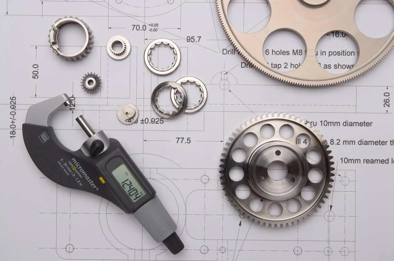
Precision-cut cogs and gears overlay technical drawings and quality control data. (Alamy)
In contemporary manufacturing, an engineering drawing is a technical document. It relates design intent to the requirements necessary to manufacture a part. The most important parameters are dimensions, tolerances, material, finishes, and notes that are used by the machinist and inspector when making the part and checking it.
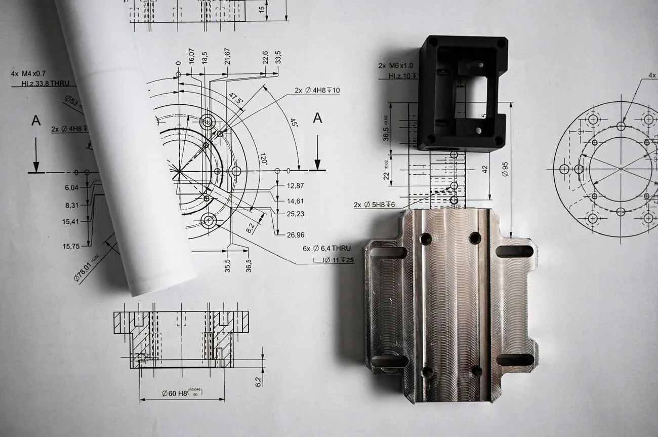
Metal components lying on mechanical engineering drawings, showcasing the relationship between design and physical realization. (Alamy)
Before machining starts, the drawing helps the team prepare the job by:
- Choosing suitable cutting tools
- Deciding the machining setup
- Planning the operation sequence
- Defining inspection checks
A CAD model defines the intended geometry of the part. In many manufacturing environments, engineering drawings remain the primary document used to communicate dimensions, tolerances, surface finishes, and inspection requirements.
A feature that looks simple in the model can require specific manufacturing steps. Hole sizes, thread details, and surface requirements can change the tooling, setup method, and inspection process used for the part.
This guide walks you through the main areas involved in reading and interpreting engineering drawings, such as:
- Views and how they represent part geometry.
- Reading dimensions, tolerances, and feature requirements.
- Identifying common symbols used for machining and inspection.
- GD&T controls and datum references.
- Reviewing drawing notes, materials, and special requirements.
- Applying drawing information during CNC machining and metal fabrication.
What Is an Engineering Drawing?
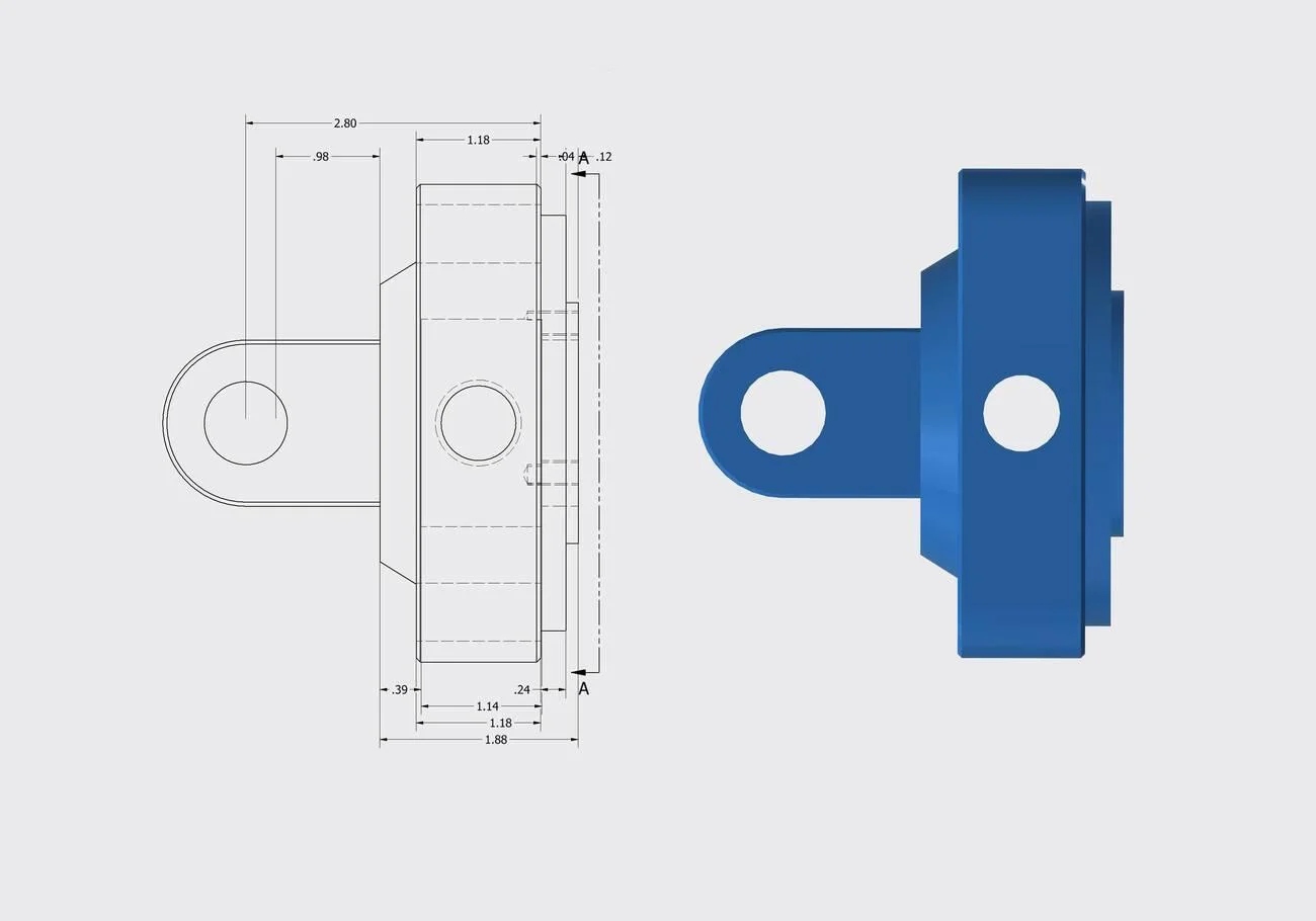
Industrial 3D CAD render showing an isometric and orthogonal layout, bracket part drawing with engineering dimensions, and views of a blue machined cast housing component. (Alamy)
An engineering drawing communicates the requirements needed to manufacture, inspect, assemble, and verify a part throughout its lifecycle. The term engineering blueprint is still used informally, although modern manufacturing relies on digital engineering drawings. Engineering drawings specify such information as size, tolerances, material grade, surface finish, and any special conditions required for production. They are often confused with engineering diagrams. A diagram explains system relationships, while a drawing defines dimensions and manufacturing requirements.
Engineering Drawings vs CAD Models
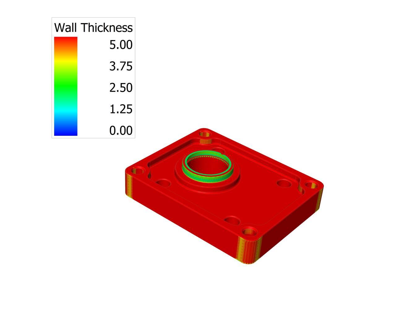
Mounting plate - CAD model technical sketch (Alamy)
A CAD model defines the 3D shape of a part. It helps engineers and machinists understand the overall design, feature locations, and part geometry.
On the other hand, an engineering drawing adds the details needed for manufacturing.
The drawing supplements the CAD model with dimensions, tolerance limits, surface requirements, and notes that are often critical during manufacturing and inspection.
| Manufacturing Information | Engineering Drawing | CAD Model |
|---|---|---|
| Critical dimensions requiring inspection | ✓ | Limited visibility |
| GD&T controls and datum structure | ✓ | May be embedded in MBD-enabled CAD models |
| Surface finish requirements | ✓ | Usually not shown |
| Thread callouts and specifications | ✓ | May require separate annotations |
| Material and finish requirements | ✓ | Often stored as metadata |
| Revision history | ✓ | Managed through CAD systems |
| Feature geometry and spatial relationships | Limited | ✓ |
| Hidden internal features | Section views required | ✓ |
| Tool accessibility review | Limited | ✓ |
| Fixture and setup planning | Supporting role | ✓ |
| Quality inspection planning | ✓ | Supporting role |
| Assembly notes and special instructions | ✓ | Rarely included |
For example, a machinist may use the CAD model to examine a deep pocket and confirm cutter access. However, the drawing may specify a:
- Flatness requirement on the pocket floor
- Surface finish callout
- Datum reference used during inspection
Missing those requirements can create additional setups, rejected parts, and unexpected inspection failures.
Before production begins, manufacturers typically review both the CAD model and the engineering drawing together. Features that appear straightforward in the model may require additional machining operations, tighter inspection controls, or special tooling once drawing requirements are considered.
If you need feedback on tolerance feasibility or machining strategy, JLCCNC can review your CAD files and engineering drawings before production.

Precision CNC Machining Service
Professional manufacturing, fast turnaround, and quality assurance.
Types of Engineering Drawings Used in Manufacturing
Different drawing types support different stages of production.
A detailed drawing is usually the document machinists work from directly. Pocket depths, hole locations, thread callouts, datum references—most programming and inspection decisions start here. If a mounting bracket contains a flatness requirement on one face, that requirement will often influence both fixturing and final inspection.
Assembly drawings serve a different role. They show how parts relate to one another after manufacturing is complete. Bearing alignment, fastener locations, shaft orientation, and clearance between moving components—these relationships are often easier to understand from an assembly view than from individual part drawings.
Fabrication and sheet metal drawings focus more on material transformation. Weld locations, bend angles, flat patterns, cut lengths, and material thickness become the primary concerns. A missing bend allowance or an incorrectly placed relief notch may not look significant on paper, but it can change the final geometry after forming.
CNC machining drawings tend to contain the largest amount of production-critical information. During drawing review, attention usually goes first to datum references and tolerance-controlled features because they determine the setup strategy. Thread details affect tooling choices. Surface finish callouts can add secondary machining operations. When several critical dimensions reference the same datum structure, inspection planning often begins before the first toolpath is programmed.
General Drawing Interpretation Workflow for Manufacturing
This review workflow is often referred to as general drawing interpretation in manufacturing environments.
Review the Title Block and Notes
Start by checking the title block before studying individual features. It provides basic information about the part and drawing requirements.
- Check the part name, drawing number, revision level, and material specification.
- Confirm the drawing units, such as mm or inches, before reading dimensions.
- Review general notes for requirements like surface finish, coating, heat treatment, or inspection details.
Understand Views, Dimensions, and Tolerances
Next, review the drawing views to understand the part shape and feature locations. Then check dimensions and tolerance values linked to each feature.
- Compare front, top, and side views to understand the complete part geometry.
- Follow dimensions to identify sizes, hole locations, depths, and feature relationships.
- Check tolerance values like ±0.05 mm to understand the allowed size variation.
Identify Symbols and Special Manufacturing Requirements
The final step is reviewing symbols and special instructions that affect production methods. These details often define machining, fabrication, or inspection requirements.
- Check symbols for threads, surface finishes, welds, and GD&T controls.
- Review requirements such as M8 thread, Ra 1.6 µm finish, or position tolerance Ø0.05 mm.
- Confirm any special processes, such as coating, heat treatment, or required inspection points, before manufacturing begins.
Reading a Drawing Step by Step
A practical sequence for reading a drawing is:
1. Check title block and revision
2. Review material specification
3. Identify datums
4. Study orthographic views
5. Review dimensions
6. Check tolerances and GD&T
7. Review notes and special requirements
8. Verify inspection-critical features
Following a consistent workflow reduces interpretation mistakes and improves manufacturing accuracy.
Understanding Drawing Views
Engineers learning how to read technical drawings often start with views and dimensions before moving into GD&T.
Drawing views show different sides and internal features of a part. Engineers use these views to understand shape, dimensions, and manufacturing requirements before production begins.
Orthographic and Isometric Views
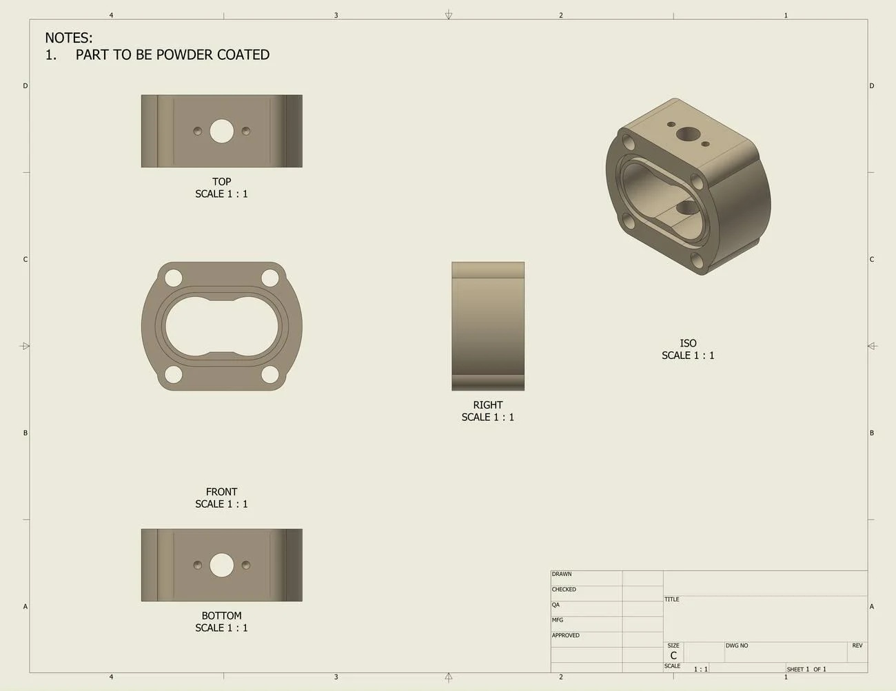
An engineering technical drawing blueprint sheet featuring orthographic views and an isometric layout of a mechanical housing component with powder coating notes. (Alamy)
- Orthographic drawings commonly include front, top, and side views. These views are used to define precise locations, dimensions, and surface relationships.
- For example, two mounting holes shown 50 mm apart with a diameter of Ø10 mm can be located precisely using orthographic views.
- Isometric views provide a 3D part representation to help understand the overall shape, angled surfaces, pockets, etc., and the layout of features before cutting.
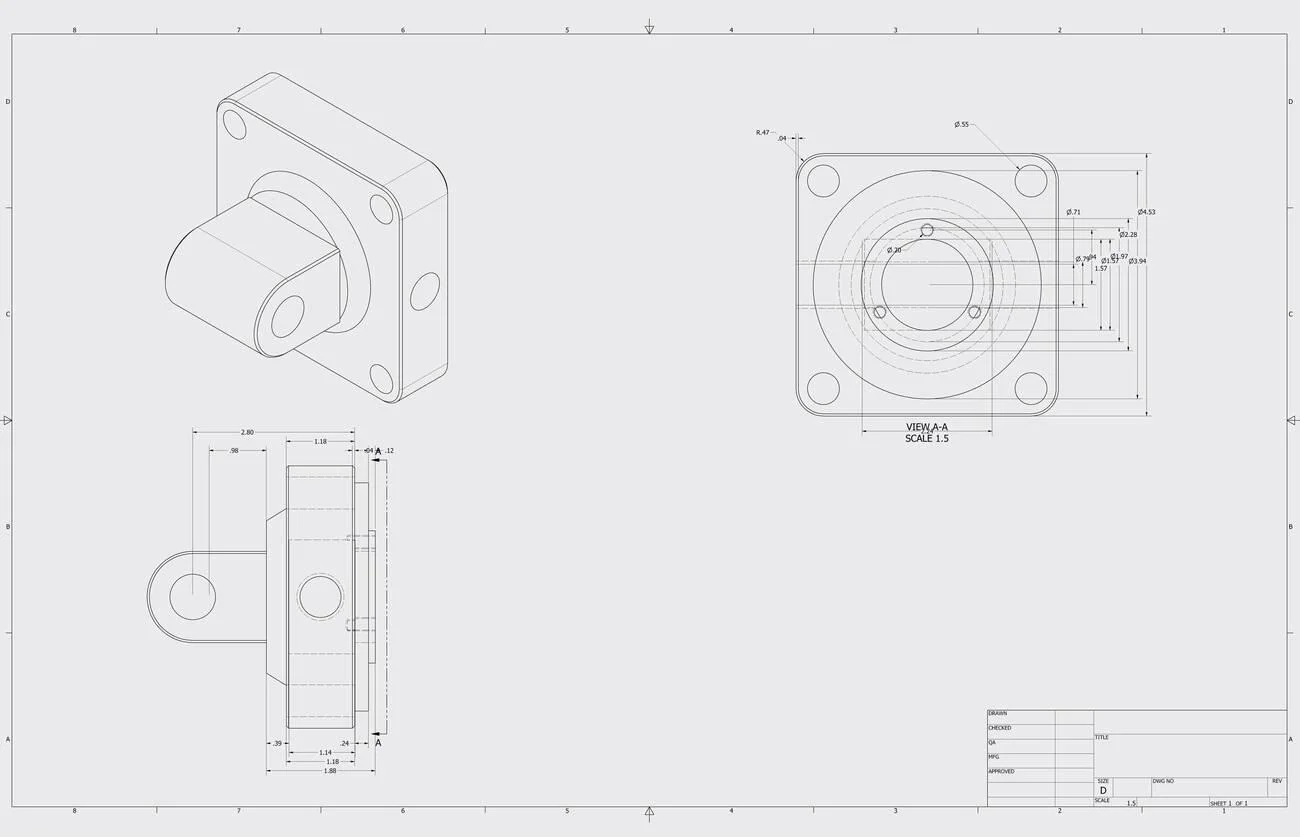 Technical blueprint illustration showing isometric, front, and side views of a flange mount component with dimensional specifications and engineering annotations. (Alamy)
Reviewing all views together helps prevent missing information. It allows engineers and machinists to check unclear areas, such as undefined hole depth, incorrect feature location, or missing reference dimensions.
Section and Detail Views
Section views cut through a part drawing to show hidden internal features. Detail views enlarge small areas that require closer attention.
- Section views show internal conditions, such as a Ø20 mm bore, 3 mm wall thickness, or 6 mm deep counterbore.
- Detail views enlarge small features, such as threads, grooves, chamfers, or corner radii, like R2 mm and 45° chamfer.
- These views provide clearer information for machining areas that cannot be measured easily from the main drawing view.
Identifying Critical Geometry
Critical geometry includes features that control part function, assembly, and manufacturing accuracy. These features usually require clear dimensions and specific inspection points.
- Hole patterns, mounting faces, and alignment features often include values such as +/- 0.02 mm position tolerance or 90° perpendicularity requirements.
- Dimensions linked to mating areas, such as bearing seats or bolt holes, need clear references from fixed datum points (Datum A, B, C).
- Reviewing feature relationships helps engineers confirm details like center distances (75 mm apart), surface angles (30°), and required fits (H7/h6).
Reading Dimensions and Tolerances
Dimensions and tolerances tell manufacturers the required part size and allowed variation. They help machinists produce parts correctly and guide inspectors during quality checks.
Linear, Hole, and Feature Dimensions
Linear dimensions show the size and location of part features. These values define lengths, distances, diameters, and depths needed during machining.
- A size like 40 +/- 0.10 mm allows the feature to measure between 39.90 mm and 40.10 mm.
- A hole callout like Ø8 THRU shows an 8 mm through hole requirement.
- A note like 20 mm from the edge tells the machinist where to place a feature.
Geometric and Limit Tolerances
Geometric tolerances control the shape and position of features. They are used for surfaces and features that must match other parts during assembly.
- A flatness tolerance of 0.05 mm limits variation across the entire surface.
- A position tolerance like Ø0.10 mm | A | B | C controls hole location from defined reference surfaces.
- Limit sizes like 10.00–10.05 mm show the acceptable measurement range directly.
Implications for Manufacturing
Tolerance values influence machining methods, inspection tools, and production planning. A drawing with clear limits helps teams select suitable processes.
- A shaft size of Ø25 ±0.02 mm may require precise turning and measurement checks.
- A larger tolerance, like ±0.5 mm, can allow standard milling operations.
- Features with location requirements need proper setups to maintain their relationship with other surfaces.
Common Symbols in Engineering Drawings
Engineering drawing symbols provide quick instructions for manufacturing and inspection. They replace lengthy notes and show requirements for surfaces, holes, threads, welds, and feature control.
Surface Finish and Hole Symbols
Surface finish and hole symbols define machining conditions and feature requirements. These symbols help manufacturers understand how a surface should be produced and checked.
| Symbol / Callout | Meaning | Practical Use |
|---|---|---|
| Ra 1.6 µm | Surface roughness requirement | A machined face may need a smoother finish for sealing or contact surfaces. |
| Ra 6.3 µm | Standard machined finish | Commonly used for general milling and turning surfaces. |
| Ø10 | Hole diameter | Shows a 10 mm diameter hole requirement. |
| Ø10 THRU | Through hole | Indicates the hole passes through the full material thickness. |
| Ø20 × 5 DP | Blind hole size and depth | Defines a 20 mm hole with 5 mm depth. |
| ⌴ Counterbore symbol | Enlarged flat-bottom hole | Used for bolt heads that need to sit below or flush with a surface. |
Thread, Welding, and GD&T Symbols
GD&T Symbols define joining features and geometric requirements. They provide specific instructions for machining, fabrication, and inspection.
| Symbol / Callout | Meaning | Practical Use |
|---|---|---|
| M8 × 1.25 | Metric thread size | Defines an 8 mm thread with 1.25 mm pitch for fasteners. |
| 1/4-20 UNC | Inch thread specification | Used for threaded holes in inch-based designs. |
| △ Fillet weld symbol | Indicates a fillet weld requirement at the specified joint | Shows where welded joints need reinforcement between parts. |
| ⌖ Position Ø0.05 | A | B |
| ⏥ Flatness 0.03 | Surface flatness control | Limits surface variation to 0.03 mm during inspection. |
| ∥ Parallelism 0.02 | Parallel surface control | Ensures two surfaces remain within the specified alignment range. |
Symbols provide standardized instructions without relying on lengthy notes.
How Datums Work
A datum is not simply a surface label shown on a drawing. In manufacturing, it often becomes the physical reference used for machining setups and inspection.
For example, the bottom face of a housing may be designated as Datum A, while two perpendicular faces establish Datum B and Datum C. Together they create the coordinate system used to locate holes, slots, and other features.
When a position tolerance references A, B, and C, the feature is measured relative to those datum references rather than to the overall part size. This approach helps maintain consistent inspection results and assembly alignment.
Example: Reading a GD&T Callout
Consider the following hole specification:
Ø10 ±0.02
⌖ Ø0.10 | A | B | C
The diameter requirement controls hole size.
The position tolerance controls hole location.
A hole could satisfy the size requirement and still fail inspection if its axis falls outside the positional tolerance zone.
This distinction is one of the most common sources of confusion when engineers first learn to read technical drawings.
Engineering Drawing Standards and Conventions
Engineering drawing standards create a common language between designers, manufacturers, and inspectors. They define drawing formats, symbols, units, and projection methods so teams can interpret part requirements correctly.
ASME and ISO Standards
ASME and ISO standards provide guidelines for creating and reading engineering drawings. They define rules for dimensions, symbols, tolerances, and drawing practices used across industries.
| Standard | Main Focus | Practical Use in Manufacturing |
|---|---|---|
| American Society of Mechanical Engineers (ASME Y14 series) | Drawing practices, GD&T, dimensioning, and tolerances | Used by manufacturers to define feature locations, datum references, and inspection requirements. |
| International Organization for Standardization (ISO 1101 and related standards) | International drawing rules and geometric specifications | Helps global teams interpret symbols, tolerances, and feature controls consistently. |
| ASME Y14.5 | Geometric Dimensioning and Tolerancing (GD&T) rules | Defines symbols for position, flatness, runout, and other geometric controls. |
| ISO GPS standards | Geometrical product specification system | Provides rules for defining product geometry and measurement requirements. |
Units, Scale, and Projection Methods
Drawings use specific units, scales, and projection methods to represent part sizes and shapes. These details help manufacturers read dimensions correctly before production.
| Drawing Element | Common Practice | Practical Example |
|---|---|---|
| Units | Millimeters (mm) and inches (in) | A drawing may specify 50 mm length or 2.000 in diameter. |
| Scale | Full-size, reduced, or enlarged view | A large machine frame may use a 1:5 scale, while a small feature may use a 5:1 scale. |
| First-angle projection | Common in many ISO-based regions | The top and side views follow a specific placement method based on the projection symbol. |
| Third-angle projection | Common in ASME-based drawings | Views are placed based on the viewing direction used in the drawing standard. |
| Drawing scale note | Shows the relationship between drawing size and actual part size | A 1:2 scale means the drawing is half the actual part size. |
First-Angle vs Third-Angle Projection
One of the first steps in reading technical drawings is identifying the projection method.
First-angle projection is commonly used in Europe and many ISO-based regions.
Third-angle projection is commonly used in the United States and ASME-based drawings.
Misinterpreting the projection system can result in viewing features from the wrong orientation and manufacturing the part incorrectly.
Common Mistakes in Reading Drawings
Engineering drawings contain many connected details. Missing a small instruction can affect machining decisions, inspection methods, or part fit during assembly.
Misreading Views or Dimensions
Drawing views must be read together because each view shows different information about the part. A wrong interpretation can change the produced geometry.
- Reading a hidden feature from the wrong view can place a hole, slot, or pocket incorrectly.
- Missing a centerline or reference point can shift feature locations during machining.
- Confusing drawing scale with actual size can lead to incorrect measurements.
Ignoring Notes or Tolerances
Notes and tolerances add requirements that are not always shown beside individual features. They define limits for materials, finishes, and manufacturing conditions.
- Missing a material note can result in selecting an unsuitable stock for production.
- Ignoring a tolerance range like 20.00–20.05 mm can affect part fit with mating components.
- Overlooking finishing instructions, such as deburring edges or Ra 3.2 µm, can affect the final part condition.
Confusing GD&T Symbols
GD&T symbols control relationships between features rather than only their size. They require careful reading because they affect measurement and setup methods.
- A position tolerance controls where a hole can be located, not the hole diameter itself.
- A flatness symbol applies to a surface condition without using a datum reference.
- Datum letters like A, B, and C establish measurement references for inspection.
Application in CNC Machining and Sheet Metal Fabrication
CNC Machining Requirements
CNC drawings guide machinists through part setup and feature creation. They define cutting areas, hole locations, threads, finishes, and dimensional limits.
A machinist uses details such as Ø15 mm bore, M6 thread, 6 mm slot width, or Ra 1.6 µm surface finish to prepare machining operations. Datum references and feature locations also guide workholding and tool movement.
Sheet Metal Fabrication Considerations
Sheet metal drawings focus on material behavior during cutting and forming. They include flat patterns, bend positions, relief details, and finished dimensions.
Fabricators use information like 1.5 mm sheet thickness, 45 mm flange height, and 90° bend angle to plan forming steps. Bend allowances and corner details help achieve the correct final shape after processing.
Inspection and Quality Verification
Inspection teams use drawings to measure finished parts against defined requirements. The drawing provides the reference points and limits for checking each feature.
Inspection usually focuses on the features that control assembly and function. Hole size may be checked with plug gauges, while positional tolerances often require CMM measurement. Surface finish verification is typically performed only on faces identified by the drawing.
How Manufacturers Review Drawings Before Quoting
Manufacturers review engineering drawings before quoting to understand production requirements, possible challenges, and required resources. This review helps identify unclear details, process limitations, and factors that affect part cost.
Manufacturability Review
A manufacturability review checks whether the part can be produced using available machines, tools, and processes. Engineers look for features that may require special setups or additional operations.
| Review Area | What Manufacturers Check | Example |
|---|---|---|
| Feature access | Whether cutting tools can reach all machining areas | A deep pocket may require a longer tool or a different setup |
| Part setup | How the component will be held during machining | Thin walls may need extra support during cutting |
| Process selection | Suitable method for producing the feature | Milling, turning, bending, or welding requirements |
| Material condition | Material type and availability | Aluminum, stainless steel, or hardened materials may need different processes |
Missing Dimensions
Manufacturers check drawings for incomplete information before starting cost calculations. Missing values can prevent accurate process planning and quoting.
| Missing Detail | Possible Issue | Example |
|---|---|---|
| Feature size | Cannot define machining operation | Hole shown without diameter value |
| Hole depth | Tool selection becomes unclear | Blind hole without depth specification |
| Material thickness | Fabrication cost cannot be estimated | Sheet metal part without thickness |
| Surface requirement | Finishing process remains unknown | No surface finish value for the sealing area |
Tolerance Risk Assessment
Tolerance review helps manufacturers understand which features require closer control during production. These requirements affect machining methods, inspection needs, and processing time.
| Drawing Requirement | Manufacturing Impact |
|---|---|
| ±0.01 mm size tolerance | May require precision machining and additional measurement checks |
| Position tolerance Ø0.05 mm | Requires controlled setups and accurate inspection methods |
| Flatness 0.02 mm | May require careful surface preparation and verification |
| General ±0.5 mm tolerance | Usually allows standard machining processes |
Cost Drivers in Drawings
Drawing details directly influence production expense. Manufacturers review features that increase machine time, tooling needs, and inspection requirements.
The following are the main cost drivers in engineering drawings.
| Cost Factor | Drawing Example |
|---|---|
| Complex geometry | Multiple pockets, angles, or curved surfaces |
| Extra operations | Separate drilling, tapping, or finishing steps |
| Material usage | Large stock size compared with finished part size |
| Inspection requirements | CMM checks for detailed geometric controls |
DFM Recommendations
Manufacturers provide Design for Manufacturing (DFM) feedback to improve production without changing the part function. These suggestions focus on easier machining, simpler fabrication, and reduced processing steps.
| Recommendation | Practical Example |
|---|---|
| Increase internal corner radius | Change R1 mm to R3 mm to reduce tool load |
| Standardize hole sizes | Use common drill sizes instead of custom tooling |
| Reduce unnecessary finishes | Apply fine surface finishes only on functional areas |
| Add clear reference dimensions | Use proper datums for critical feature locations |
Best Practices for Manufacturing Drawing Review
A drawing review should focus on details that affect production decisions. Engineers check feature requirements, process limitations, and document accuracy before releasing parts for manufacturing.
Verify Critical Dimensions
Start with dimensions that control part fit, movement, or connection with other components. These features usually include holes, mounting faces, shafts, and locating surfaces.
Check values such as hole diameter, center distance, bore size, and surface position against the design requirement. For example, a Ø25 H7 bore needs careful review because it may connect with a bearing or shaft.
Check Manufacturing Feasibility
Review whether the design features match the planned production method. Some shapes require special tools, extra setups, or different manufacturing approaches.
Look at areas such as deep cavities, narrow slots, thin sections, and complex angles. A 3 mm internal corner radius may require a smaller cutting tool, while increasing it can allow faster machining.
Confirm Revision Status
Check the drawing version before sending files to production or suppliers. The latest revision contains the current design changes and approved requirements.
Compare the revision letter, release date, and updated notes with previous versions. This prevents teams from producing parts from outdated dimensions or removed features.
Conclusion About Engineering Drawings
Engineering drawings provide the information needed to turn designs into finished parts. Reading views, dimensions, tolerances, and symbols correctly helps manufacturers plan processes and avoid production issues.
A complete drawing review allows engineers to identify feature requirements, machining needs, and inspection points before manufacturing begins. Clear drawings also improve communication between designers, machinists, and quality teams throughout the production process.
Need help with CNC machining based on your engineering drawings? JLCCNC provides precision CNC machining services with support for design review, material selection, tolerance analysis, and production requirements. Share your CAD files and drawings with our team to discuss your project needs and receive manufacturing guidance.
Precision CNC Machining Service
Professional manufacturing, fast turnaround, and quality assurance.
FAQ About Engineering Drawings
Q: How do you read an engineering drawing?
Start with the title block, then review views, dimensions, tolerances, and symbols. Check how features relate to each other before using the drawing for manufacturing.
Q: What is the first thing to check on a drawing?
Begin with the title block and revision information. Confirm the part name, drawing number, material, units, and latest update before reviewing feature details.
Q: What do common symbols mean?
Symbols provide specific instructions without adding long notes. For example, Ø shows diameter, R defines radius, M indicates metric threads, and GD&T symbols control feature relationships.
Q: How do tolerances affect manufacturing?
Tolerances define the allowed size variation for a feature. A value like 50 ±0.05 mm gives the acceptable range needed for machining and inspection.
Q: How are drawings applied in CNC and sheet metal fabrication?
CNC machinists use drawings for dimensions, tool paths, holes, threads, and surface requirements. Sheet metal fabricators use them for material thickness, bends, flat patterns, and forming details.
Q: What is the difference between an engineering drawing and a CAD model?
A CAD model shows the 3D shape of a part, while an engineering drawing provides manufacturing instructions. Drawings include dimensions, tolerances, materials, and notes needed for production.
Q: Is an engineering blueprint the same as an engineering drawing?
Yes, in most cases, they refer to the same type of document. Blueprint is an older term originally linked to a printing process, while engineering drawing is the modern technical term. Both are used to communicate dimensions, tolerances, materials, and manufacturing requirements.
Keep Learning
Counterbore Holes: Symbols, Callouts, Dimensions & Applications
Key Takeaways A counterbore provides extra space above a hole so the fastener head does not project above the part surface. Socket head cap screws are commonly installed in counterbore holes because the recess matches the shape of the screw head. Three dimensions define the feature: the hole size, the recess diameter, and the recess depth. The hole and the recess are machined on the same centerline to maintain proper alignment between the hole and the recessed seating surface. In most applications, th......
Differences Between Tolerance and Allowance
Key Takeaways Tolerance controls the allowable variation of a single dimension, while allowance is the intentional difference between two mating parts that determines the type of fit. Tolerance and allowance are closely related but describe different aspects of dimensional control. Tolerance defines the acceptable variation of a single dimension, while allowance defines the intentional difference between mating parts to achieve a required fit. Confuse them and you end up with parts that either won't a......
Types of Holes in Engineering: Design, Symbols, and Manufacturing Guide
Types of holes in engineering - illustration (Erye rubber & plastic parts) Key Takeaways Engineering holes are used to support fastening, alignment, bearing installation, fluid flow, and other functional requirements. The main types of holes include through holes, blind holes, threaded holes, counterbore holes, countersink holes , spotface holes, screw clearance holes, reamed holes, and dowel holes. Hole geometry determines the required machining process. Some holes only require CNC drilling , while o......
True Position in GD&T: Symbol, Formula, Tolerance, and Manufacturing Applications
Key Takeaways About True Position True position defines the allowable variation in a feature's location from its basic dimensions. The control applies to holes, slots, pins, threaded features, and datum features. A circular tolerance zone controls features in 2D, while a cylindrical zone controls feature axes in 3D. Datum references establish the coordinate system used for manufacturing and inspection. Maximum Material Condition (MMC) adds bonus tolerance as the feature departs from its maximum materi......
Tolerance Stack-Up: Analysis, Examples, and How It Affects Manufacturing and Assembly
Key Takeaways About Tolerance Stack-Up Tolerance stack-up determines the dimensional variation that accumulates across multiple features and assembled parts. The stack-up study allows engineers to identify gaps, interference issues, alignment shifts, and fit conditions before production starts. Small dimensional variations from several parts can combine and create larger assembly issues. Usually, worst-case analysis evaluates the maximum possible variation by combining all tolerance limits. Statistica......
How to Read Engineering Drawings: Symbols, Dimensions, and Practical Interpretation
Key Takeaways About Engineering Drawings Engineering drawings communicate product requirements throughout manufacturing, inspection, assembly, and quality control. They communicate information that may not be fully defined in a CAD model, such as allowable variation, surface requirements, and inspection points. A drawing review starts with understanding the part reference system. The machinist checks which surfaces are used as datums, how features relate to each other, and which areas need access duri......