Counterbore Holes: Symbols, Callouts, Dimensions & Applications
19 min
- What Is a Counterbore?
- Counterbore Symbols and Callouts
- Counterbore Hole Dimensions
- Counterbore Hole Examples
- Counterbore vs Countersink vs Spotface: Key Differences
- How Counterbore Holes Are Machined
- Designing Counterbore Holes
- Common Counterbore Design Mistakes
- FAQs About Counterbores
Key Takeaways
- A counterbore provides extra space above a hole so the fastener head does not project above the part surface.
- Socket head cap screws are commonly installed in counterbore holes because the recess matches the shape of the screw head.
- Three dimensions define the feature: the hole size, the recess diameter, and the recess depth.
- The hole and the recess are machined on the same centerline to maintain proper alignment between the hole and the recessed seating surface.
- In most applications, the hole is drilled first, and the counterbore is cut afterwards using a counterbore tool, an end mill, or a boring tool.
- On engineering drawings, a counterbore is usually shown with the ⌴ symbol followed by the required dimensions.
- Standard dimensions simplify tool selection, inspection, and replacement with standard fasteners.
- Counterbore holes are widely used in fixtures, molds, machine frames, tooling plates, hydraulic components, and many other assembled parts.
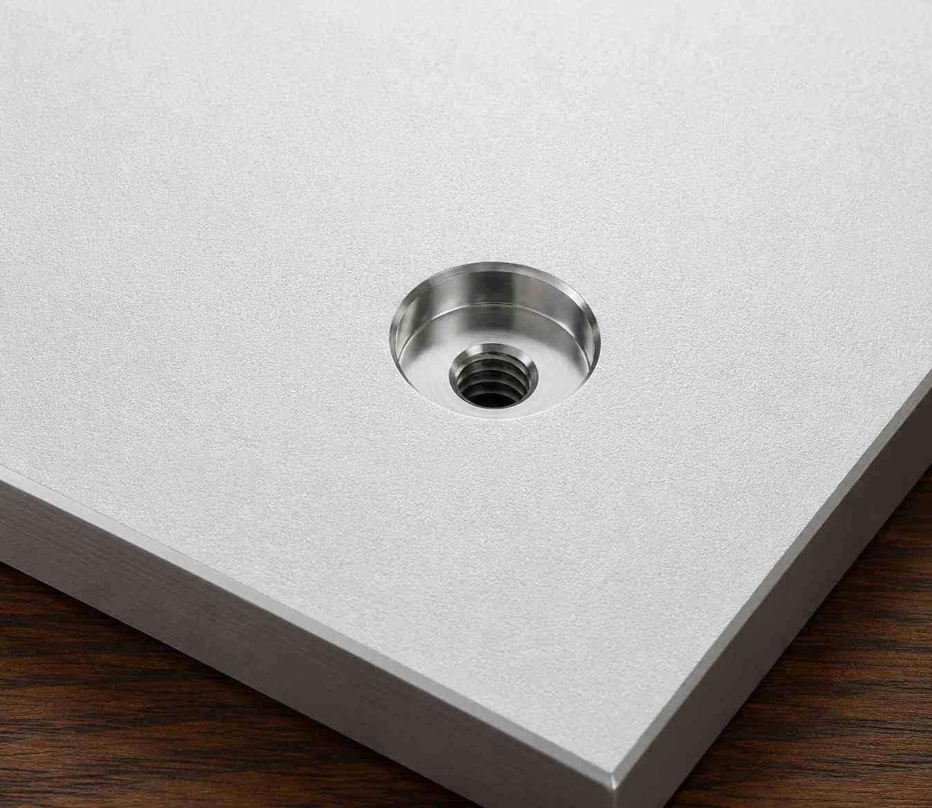
Counterbore hole (Wikipedia)
Many mechanical parts use fasteners that should not extend above the finished surface. A drilled hole alone cannot provide enough space for the fastener head, so an additional recess is machined at the top of the hole. This recess is called a counterbore.
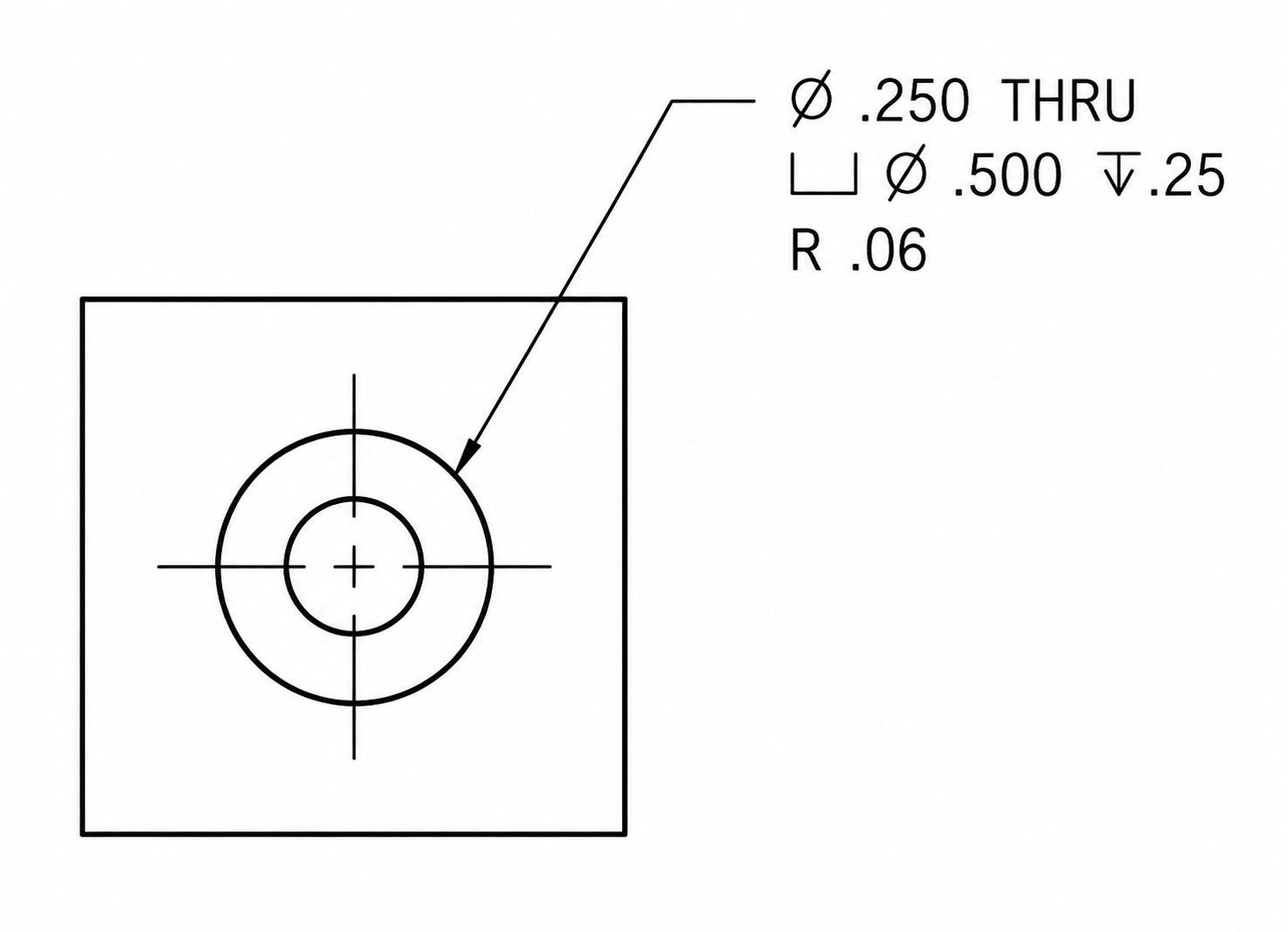
Counterbore dimension in Fusion 360
Although it is a simple feature, the counterbore dimensions must match the selected fastener. The recess needs enough room for the fastener head without removing more material than necessary. If the dimensions are not checked carefully, the fastener may not fit as expected, and the part could need another machining operation.
In most cases, the hole is drilled first, and the counterbore is machined afterwards. Keeping both operations in the same setup helps the recess stay centered over the hole and makes the finished feature easier to inspect.
In this guide, we will explain:
- What a counterbore is and how it differs from similar hole features.
- How to read counterbore symbols and drawing callouts.
- How counterbore dimensions are selected.
- Common CNC machining and inspection methods.
- Design practices that help simplify manufacturing and assembly.
What Is a Counterbore?
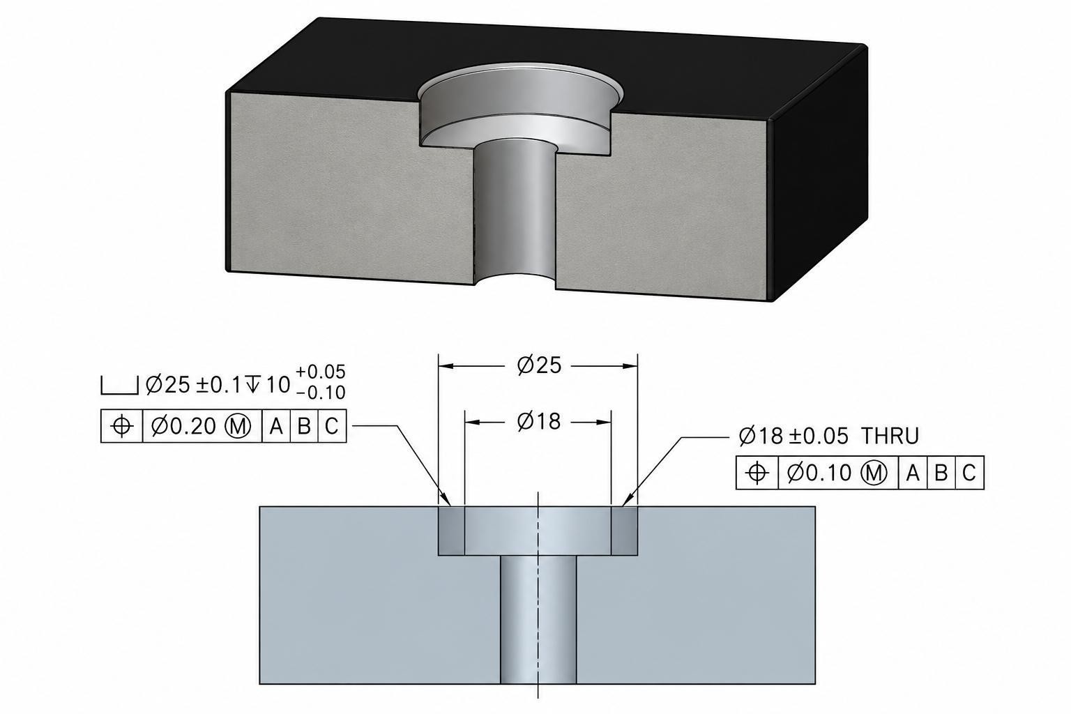
Dimensioning a counterbore hole
A counterbore is a cylindrical recess. It is machined above a hole to provide a flat seating surface for the head of a bolt, screw, pin, or fastening component. On engineering drawings, it is identified by the ⌴ symbol.
Counterbore vs Standard Drilled Hole
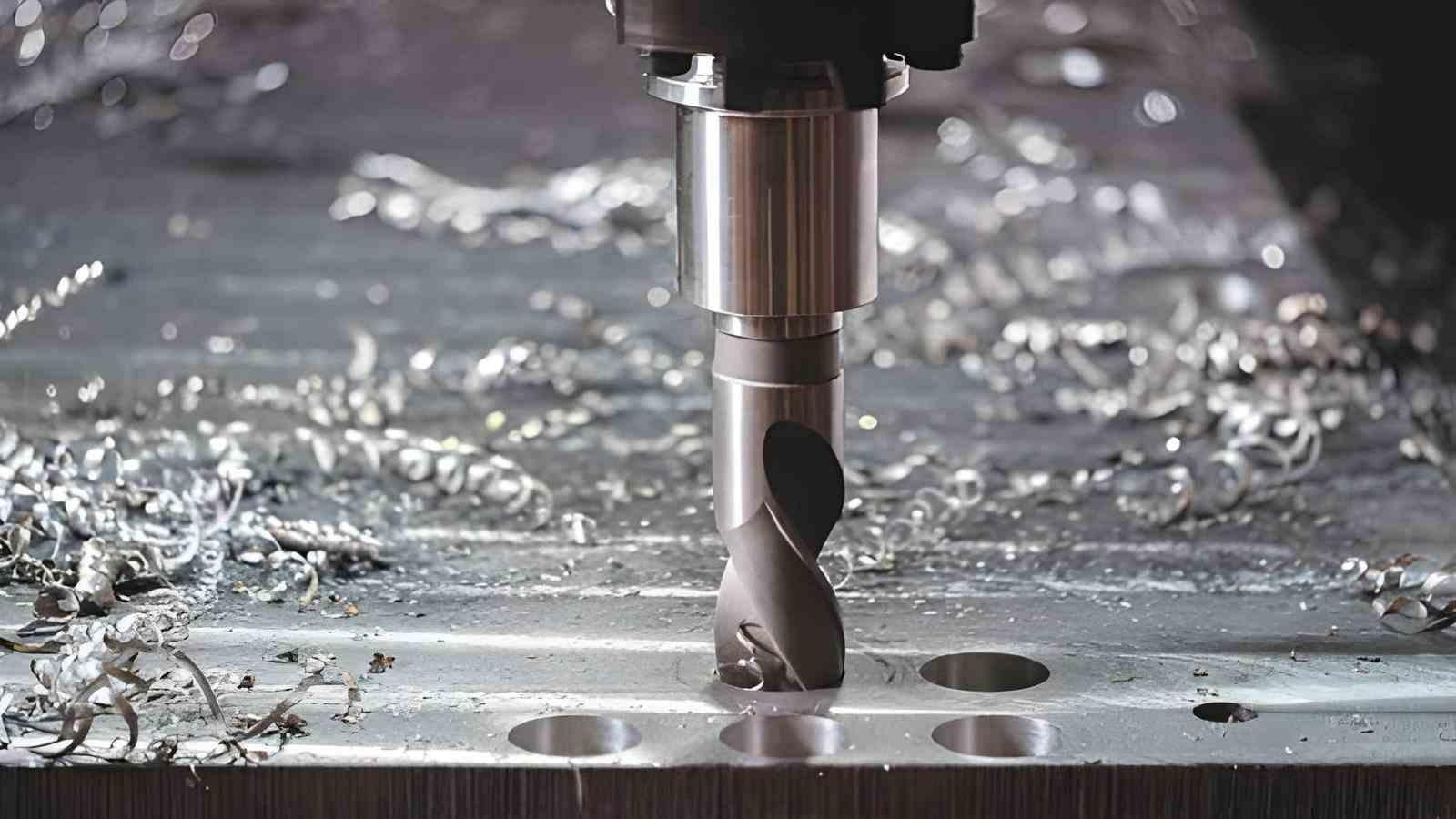
CNC hole drilling (iStock)
A drilled hole provides clearance, threading, pin location, and fluid passage. A counterbore adds a recessed seating area above that hole. This allows the fastener head to sit inside the component instead of above it.
The table below highlights the main differences between these two hole features.
| Feature | Standard Drilled Hole | Counterbore Hole |
|---|---|---|
| Primary purpose | Produces a hole through the material | Adds a recessed seating area above a hole |
| Hole geometry | Single diameter | Two diameters with a flat-bottom recess |
| Fastener head position | Remains above the surface | Sits flush with the surface or below it |
| Bottom shape | Drill point angle | Flat-bottom counterbore with drilled hole beneath |
| Drawing symbol | Hole diameter only | Counterbore symbol with recess diameter and depth |
| Typical machining | Drilling | Drilling followed by counterboring |
| Common fasteners | Bolts, pins, threaded holes | Socket head cap screws, shoulder bolts |
| Typical applications | General fastening, fluid passages, locating holes | Machine bases, fixtures, molds, precision assemblies |
Why Are Counterbore Holes Used?
Counterbore holes are used because a standard drilled hole cannot provide space for the fastener head. The additional recess helps the fastener fit the way the assembly is designed.
Some common reasons include:
- Keep the fastener below the surface.
- Provide a flat seating surface for better contact during tightening.
- Reduce the overall assembly height.
- Protect the fastener head.
- Make servicing easier.
Counterbore Symbols and Callouts
Most engineering drawings use a standard counterbore callout instead of written instructions. Once the symbol and dimensions are shown, the machinist has the details needed to machine the complete feature.
Counterbore Symbol
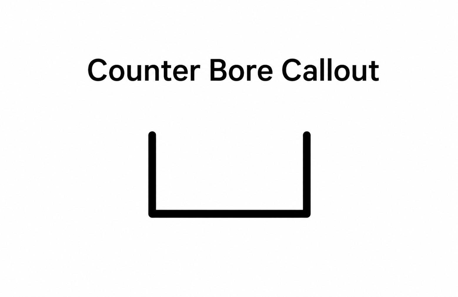
Counterbore symbol
The ⌴ symbol shows that the hole includes a flat-bottom counterbore above the main hole. It tells the machinist to machine both the drilled hole and the larger recess shown in the drawing.
Key points about the counterbore symbol:
- It identifies a flat-bottom recess above the main hole.
- It appears before the counterbore diameter in the callout.
- It is used together with the recess depth when required.
- Counterbore symbols follow standard engineering drawing conventions used in ASME and ISO drafting practices.
- It distinguishes a counterbore from a countersink and a spotface.
Reading a Counterbore Callout
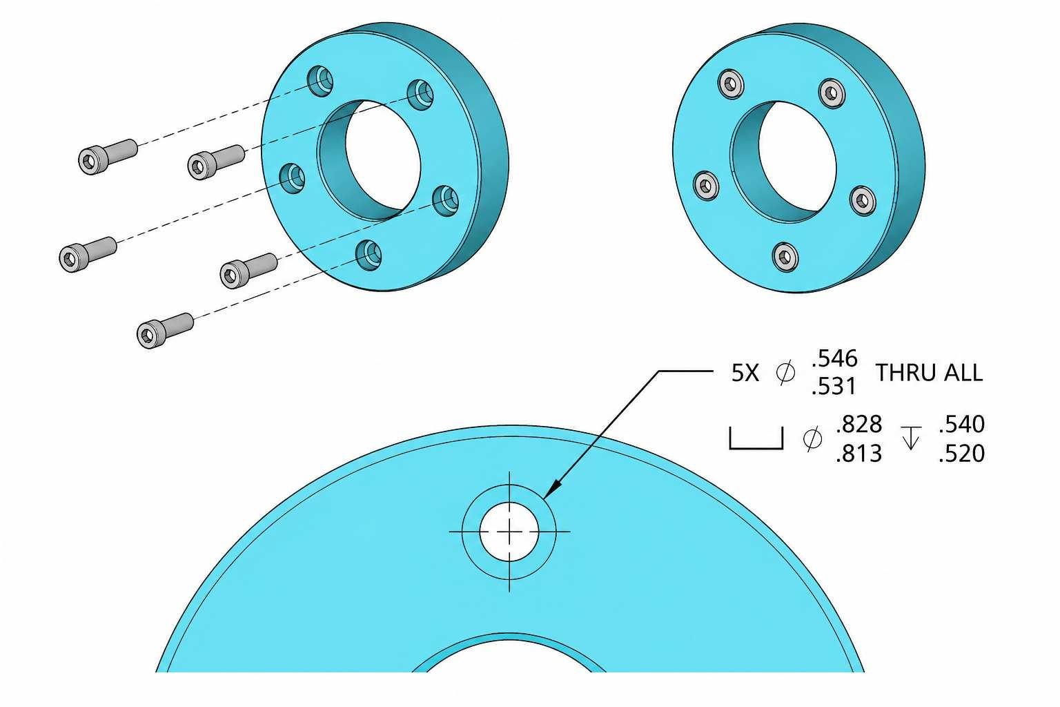
Counterbore GD&T basics (Engineering Essentials)
A counterbore callout combines the dimensions. It normally includes the hole diameter, the counterbore symbol, the recess diameter, and the recess depth.
Before machining begins, engineers verify that these dimensions match the selected fastener so the head seats correctly after assembly.
A typical counterbore callout includes:
- Hole diameter.
- Counterbore diameter.
- Counterbore depth.
- Thread specification if the hole is threaded.
- Tolerance requirements when specified on the drawing.
Common Counterbore Callout Examples
Although the format varies slightly between companies, the information remains the same. Each callout defines the hole size together with the dimensions of the recessed section.
The following examples show how counterbore callouts are commonly presented on engineering drawings.
| Drawing Callout | Meaning |
|---|---|
| Ø8 ⌴ Ø14 × 8 | 8 mm hole with a 14 mm counterbore, 8 mm deep |
| Ø10 ⌴ Ø18 × 10 | 10 mm hole with an 18 mm counterbore, 10 mm deep |
| M8 ⌴ Ø13 × 9 | M8 threaded hole with a 13 mm counterbore, 9 mm deep |
| Ø6 THRU ⌴ Ø11 × 6 | 6 mm through hole with an 11 mm counterbore, 6 mm deep |
| Ø12 ⌴ Ø20 × 12 | 12 mm hole with a 20 mm counterbore, 12 mm deep |
Before releasing a drawing, engineers also check that:
- The counterbore diameter matches the fastener head.
- The recess depth provides enough seating.
- Enough material remains below the counterbore to support the required clamping load.
Counterbore Hole Dimensions
You cannot choose each counterbore dimension on its own. The hole diameter, recess diameter, and depth should all suit the fastener you plan to use. If you change one dimension, you will usually need to check the others before machining starts.
Counterbore Diameter
Start with the fastener head size, then choose a counterbore diameter that provides enough assembly clearance.
Avoid making the recess unnecessarily large because it removes material that the fastener head could otherwise bear against.
Before releasing the drawing, check that standard tooling can machine the selected diameter without difficulty.
Counterbore Depth
Depth controls the final position of the fastener head after assembly. Some designs require the head to sit flush with the surface, while others place it slightly below the top face.
The specified depth should also leave enough material beneath the recess. Cutting deeper than required increases machining time and reduces the remaining section of the part.
Through Hole Diameter
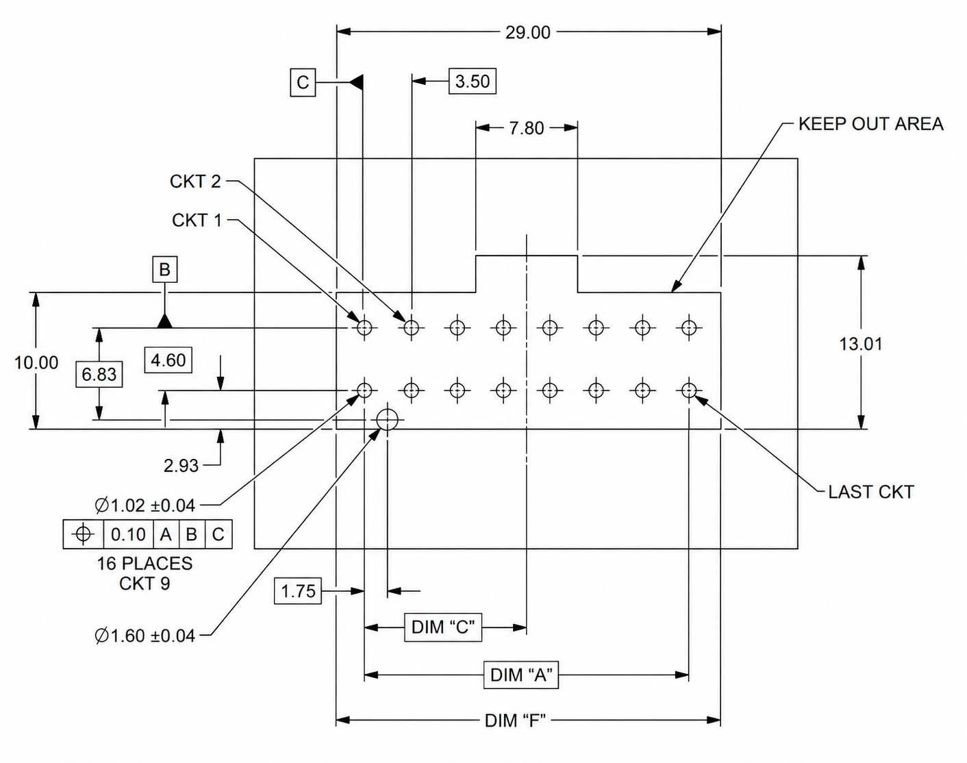
Through Hole Diameter (Electrical Engineering Stack Exchange)
The through hole is machined on the same centerline as the counterbore.
It may provide clearance for the fastener shank or contain internal threads when a threaded hole is required.
Select the hole diameter according to the fastener or locating pin used in the assembly.
The same counterbore can be paired with different hole sizes, depending on whether the hole is for clearance, threading, or a dowel pin.
When counterbore dimensions are defined on a drawing, the feature needs to be checked against the selected fastener and machining capability before production. JLCCNC reviews counterbore requirements during the DFM process to confirm feature geometry and drawing details before CNC machining begins.

Precision CNC Machining Service
Upload your CAD files to receive a CNC machining quote and engineering review for your part.
Standard Counterbore Sizes
Most counterbores follow standard dimensions for metric and inch fasteners. The table below shows common metric counterbore dimensions used for socket head cap screws. Values may vary depending on the fastener standard.
Using standard dimensions also makes it easier to source cutting tools, inspect finished parts, and replace fasteners during assembly without modifying the original design.
| Screw Size | Hole Diameter (mm) | Counterbore Diameter (mm) | Counterbore Depth (mm) |
|---|---|---|---|
| M4 | 4.5 | 8 | 4.5 |
| M5 | 5.5 | 9 | 5.5 |
| M6 | 6.6 | 11 | 6.5 |
| M8 | 9.0 | 14 | 8.5 |
| M10 | 11.0 | 18 | 10.5 |
| M12 | 13.5 | 20 | 13 |
Counterbore Hole Examples
The size of a counterbore depends on the fastener it is designed to hold. Engineers first select the screw, then choose standard counterbore dimensions that provide proper clearance and fit. Using standard sizes also makes machining and inspection much simpler.
Socket Head Cap Screw Example
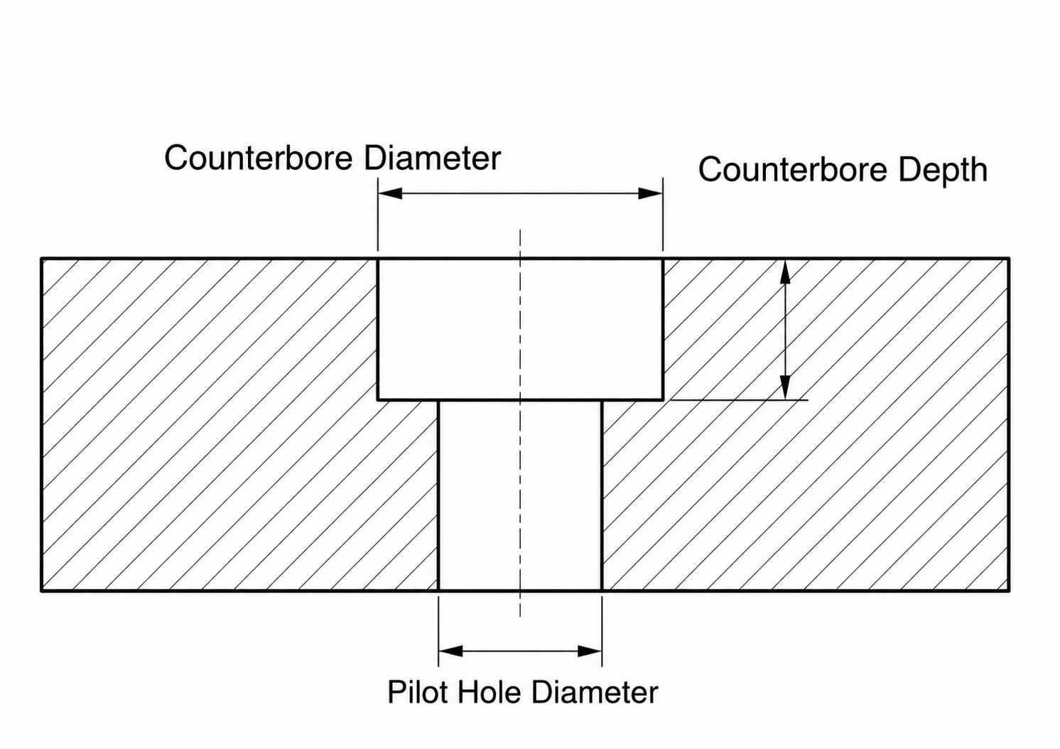
Counterbore Hole Size for Socket Head (The Engineer's Bible)
Socket head cap screws are often used with counterbore holes. The recess gives the screw head enough space, so it sits flush with or slightly below the surface after tightening.
For example, an M8 socket head cap screw typically uses:
- Through hole: Ø9 mm
- Counterbore diameter: Ø14 mm
- Counterbore depth: 8.5 mm
These dimensions provide clearance for the screw while allowing the head to seat fully inside the recess.
Engineering Drawing Example
A counterbore drawing includes the dimensions for both the hole and the recessed section. Reading the complete callout helps the machinist produce the feature correctly during a single setup.
A typical drawing note may appear as:
Ø8 ⌴ Ø14 × 8
This callout means:
- The main hole diameter is 8 mm.
- The counterbore diameter is 14 mm.
- The counterbore depth is 8 mm.
- Both features share the same centerline.
Additional notes such as tolerances, threads, and surface finish may also appear if the design requires them.
Selecting Dimensions for a Fastener
Counterbore dimensions should match the selected fastener rather than be estimated during drawing preparation. Using standard fastener data helps prevent assembly problems and avoids unnecessary machining changes later.
A practical selection process includes:
- Choose the fastener size first.
- Select the recommended clearance hole.
- Use the standard counterbore diameter for that fastener.
- Specify a depth that seats the head as required.
- Confirm enough material remains beneath the recess before releasing the design.
Counterbore vs Countersink vs Spotface: Key Differences
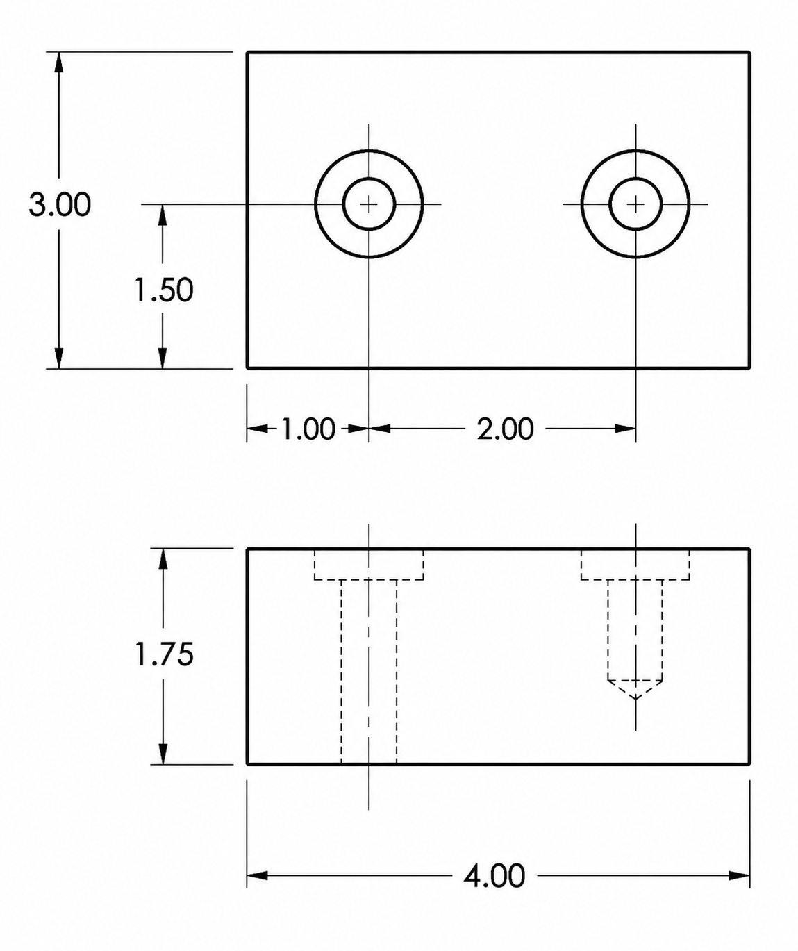
Dimensioning Counterbored and Countersunk Holes (Peachpit)
Although all three features modify the top of a hole, they produce different seating surfaces and require different machining operations. The drawing, fastener type, and assembly method determine which feature should be used.
Choosing the Right Hole Feature
The function of the joint usually determines the feature before machining begins.
- A counterbore is suitable when the fastener head must sit below the surface while maintaining full contact on a flat seat.
- A countersink is selected for flat head screws that become part of the finished surface after assembly.
- A spotface is applied to cast or forged parts that do not provide a naturally flat seating area.
The surrounding material should also be checked because deep recesses and thin walls may reduce local strength.
If standard fasteners are used, matching the feature dimensions to recognized fastener standards simplifies machining and inspection.
| Feature | Counterbore | Countersink | Spotface |
|---|---|---|---|
| Machined Geometry | Flat-bottom cylindrical recess | Conical recess | Shallow flat machined pad |
| Seating Surface | Flat | Angled | Flat |
| Typical Included Angle | 90° side walls | 82°, 90°, or 100° | Not angle-dependent |
| Head Style Supported | Socket head cap screws, shoulder bolts | Flat head screws | Hex bolts, nuts, washers |
| Material Removal | Moderate | Low | Minimal |
| Depth Control | Critical for head seating | Controlled by diameter and angle | Only enough to clean the surface |
| Surface Condition | Produces a recessed mounting face | Produces a flush screw seat | Produces a flat bearing surface on rough stock |
| Common Manufacturing Processes | Drilling followed by counterboring | Drilling followed by countersinking | Drilling followed by spotfacing or face milling |
| Typical Components | Machine bases, fixtures, gearbox housings | Covers, sheet metal parts, enclosures | Castings, forgings, valve bodies, flanges |
How Counterbore Holes Are Machined
A counterbore is usually produced in two machining steps. The main hole is created first, then a larger cutter machines the flat-bottom recess. Keeping both operations on the same centerline is important because the fastener head must sit squarely inside the counterbore.
Common Counterbore Machining Methods
The machining method usually depends on the drawing, production volume, and the tools available in the shop.
Common approaches include:
- Drill the main hole first, then machine the counterbore using a counterbore cutter.
- Use an end mill if the required counterbore size is not available as a standard cutter.
- Machine both features on a machining centre during the same setup for better alignment.
- Produce simple counterbores on a drill press for low-volume work.
Counterbore Tools and Cutters for CNC Machining
The tool selection depends on the counterbore size, part material, and production requirements. For standard fastener sizes, a piloted counterbore cutter is often used because the pilot follows the existing hole and keeps the recess aligned with the drilled feature.
For custom dimensions or low-volume parts, an end mill can also machine a counterbore by controlling the diameter and depth through the CNC toolpath. This approach is useful when a standard counterbore cutter does not match the required size.
In production machining, dedicated counterbore tools can reduce setup time and improve consistency, especially when a part contains many repeated features. Before machining, the cutter diameter, depth capability, and tool rigidity should be checked against the drawing requirements.
Machining Counterbore Holes on CNC Machines
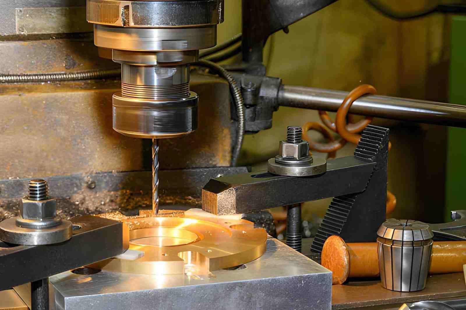
Counterbore hole drilling on a brass ring
On a CNC machine, the hole and counterbore are normally completed in one setup. This keeps both features concentric and removes the need to reposition the workpiece between operations.
A typical machining sequence is simple:
- Drill the main hole to the specified diameter.
- Change to a counterbore tool or end mill.
- Machine the recess to the required diameter and depth.
- Remove burrs before inspection if required.
Programming both operations in the same setup also reduces alignment errors between the hole and the counterbore.
Inspecting Counterbore Diameter and Depth
The finished feature is checked before the part moves to assembly. Diameter and depth are the two dimensions that receive the most attention because they determine how the fastener seats.
Common ways to check a counterbore include:
- Measure the counterbore diameter to confirm it matches the required size.
- Check the recess depth using a depth gauge.
- Make sure the counterbore lines up correctly with the through hole.
- Test-fit the specified fastener if the drawing requires an assembly check.
Material Considerations
Counterbore machining parameters are adjusted based on material properties. Aluminum allows higher cutting speeds and easier chip removal, while stainless steel and titanium usually require more conservative cutting parameters and stronger attention to tool wear. Engineering plastics such as PEEK require proper tool selection to avoid heat buildup and dimensional variation.
Designing Counterbore Holes
A counterbore should suit both the fastener and the part. Engineers usually check the recess size, remaining wall thickness, and available machining space before finalizing the drawing. These small details help the part assemble as intended.
Match Counterbore Dimensions to Standard Fasteners
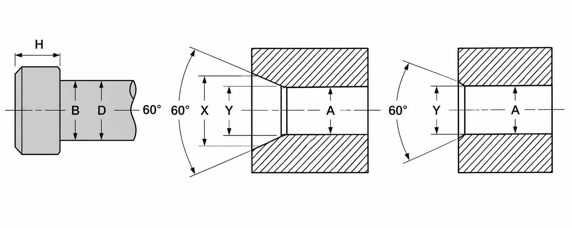
Metric Counterbore Hole Dimensions (AmesWeb)
Start with the fastener instead of the hole. Standard fasteners already have recommended clearance holes, head diameters, and counterbore depths.
Using standard dimensions offers several advantages:
- Simplifies machining and inspection.
- Supports commonly available cutting tools.
- Makes fastener replacement easier during maintenance.
- Reduces custom drawing revisions.
Maintain Adequate Wall Thickness
The counterbore removes additional material from the area surrounding the hole, so the surrounding section should remain strong enough for the intended load.
Before releasing the design, check:
- The distance from the counterbore to the part edge.
- The remaining material around adjacent holes.
- Thin sections created by deep counterbores.
- Nearby pockets or slots that reduce wall thickness.
These checks help avoid weak areas that may crack or deform during assembly.
Specify Appropriate Tolerances
Not every counterbore requires the same level of dimensional control. Functional surfaces should be controlled, while non-critical features can use general drawing tolerances.
In CNC machining, achievable counterbore accuracy depends on the material, tool selection, machine capability, and feature requirements. Tight control may be required for diameter, depth, or position when the fastener fit or assembly alignment is critical.
It is good practice to specify tolerances for:
- Counterbore diameter if the fastener fit is important.
- Counterbore depth when the head position must be controlled.
- Hole position if multiple parts are assembled.
- Surface finish only for seating surfaces that require it.
Follow Engineering Drawing Standards
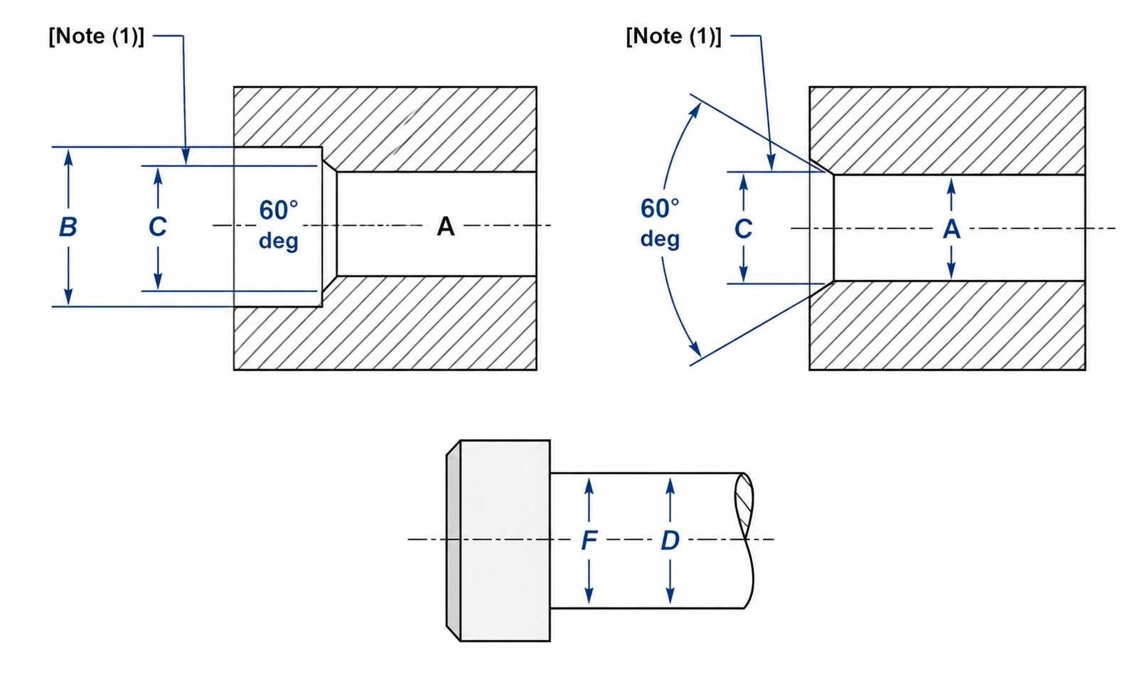
Drill and Counterbore Sizes (Engineers Edge)
A complete drawing makes the feature easier to machine and inspect. Missing dimensions or unclear callouts often lead to questions during production.
A counterbore callout should clearly define:
- Through hole diameter.
- Counterbore diameter.
- Counterbore depth.
- Required tolerances, if applicable.
- Thread information when the hole is threaded.
Using standard drawing practices keeps the design clear and reduces interpretation differences between design, machining, and inspection teams.
Common Counterbore Design Mistakes
Most counterbore problems begin during the design stage rather than during machining. An incorrect callout or a mismatched fastener can lead to assembly issues, additional machining, or part rejection. Reviewing the hole dimensions before releasing the drawing helps avoid these problems.
Confusing Counterbores with Countersinks
Although both features are machined around a hole, they are designed for different fastener heads.
Common Mistakes
- Using a counterbore for a flat head screw.
- Specifying a countersink hole for a socket head cap screw.
- Selecting the wrong symbol on the engineering drawing.
- Assuming both features can be used interchangeably.
A simple check of the fastener type before creating the drawing usually prevents these errors.
Incorrect Callout Dimensions
Every counterbore callout should include enough information for machining and inspection. Missing or incorrect values often result in production questions or additional setup time.
Common Issues
- Counterbore depth is omitted.
- Counterbore diameter does not match the selected fastener.
- Through hole diameter is incorrect.
- Metric and inch dimensions are mixed in the same callout.
- The drawing does not specify the required units.
A complete and consistent callout helps the machinist produce the feature without making assumptions.
Counterbore Depth That Is Too Shallow or Too Deep
Counterbore depth determines how the fastener head sits after assembly. If the recess is too shallow, the head may remain above the surface. If it is deeper than necessary, additional material is removed without improving the assembly.
The specified depth should match the fastener head height and the intended seating position shown on the drawing.
Selecting the Wrong Fastener Size
Counterbore dimensions should always be based on the selected fastener. Changing the screw size without updating the hole dimensions can create clearance problems during assembly.
Before finalizing the drawing, confirm that the clearance hole, counterbore diameter, and counterbore depth all correspond to the same fastener standard. This simple review helps avoid machining changes and assembly issues later in production.
Precision CNC Machining Service
Professional manufacturing, fast turnaround, and quality assurance.
FAQs About Counterbores
Q: Can CNC machining produce counterbore holes?
Yes. CNC machining is commonly used to produce counterbore holes with controlled diameter, depth, and alignment. The typical process involves drilling the main hole first, then machining the larger flat-bottom recess using a counterbore cutter or an end mill. CNC machines can complete both operations in the same setup, which helps maintain concentricity between the hole and the counterbore.
The required tool selection and machining parameters depend on the part material, counterbore size, tolerance requirements, and production volume.
Q: What is a counterbore?
A counterbore is a cylindrical recess machined around the top of a hole. It creates a flat seating surface so the head of a socket head cap screw or similar fastener can sit flush with or below the part surface.
Q: What is a counterbore hole?
A counterbore hole combines two features on the same centerline: a standard hole and a larger flat-bottom recess above it. The lower hole provides clearance or threading, while the upper recess accommodates the fastener head.
Q: What is the counterbore symbol?
The counterbore symbol is ⌴. On an engineering drawing, it appears before the counterbore diameter and depth to show that a cylindrical recess is required.
Q: How do you read a counterbore callout?
Read the hole diameter first, followed by the counterbore symbol, the counterbore diameter, and the counterbore depth.
Q: What is the difference between a counterbore and a countersink?
A counterbore has a flat-bottom cylindrical recess for socket head cap screws. A countersink has a conical recess for flat head screws that sit flush with the surface.
Q: What is the difference between a counterbore and a spotface?
A counterbore creates a recessed pocket for the fastener head. A spotface only machines a shallow flat seating area and removes only enough material to create a flat seating surface.
Q: How deep should a counterbore be?
The depth depends on the fastener head height and the required assembly position. In many designs, the depth allows the fastener head to sit flush with or slightly below the surface.
Q: How are counterbore holes machined?
The hole is usually drilled first, followed by machining the recess with a counterbore cutter or an end mill. On CNC machines, both operations are commonly completed in the same setup to keep the features aligned.
Q: Can a counterbore be machined with an end mill?
Yes, an end mill can machine a counterbore if the tool size matches the required diameter and a flat-bottom recess is needed. Dedicated counterbore cutters are still preferred for production work because they simplify the operation and produce consistent dimensions.
Conclusion About Counterbore Holes
Counterbore holes are designed around the fastener as much as the hole itself. The recess diameter, depth, and through hole need to match the selected hardware so the fastener seats correctly and the assembled part performs as intended.
During manufacturing, a counterbore feature requires accurate alignment between the drilled hole and the recessed seat. Clear drawing callouts and suitable dimensions help reduce machining adjustments and inspection issues after production begins.
Although a counterbore is a simple feature, small changes to the recess size or depth can affect assembly and part strength. Reviewing the fastener specification and available machining approach during the design stage helps avoid unnecessary revisions later.
JLCCNC machines counterbore features for CNC machined parts based on customer drawings and engineering requirements. During DFM review, JLCCNC evaluates the counterbore geometry, tool accessibility, and drawing details to confirm that the feature can be produced as specified.
Precision CNC Machining Service
Upload your CAD files to receive a CNC machining quote and engineering review for your counterbore requirements.
Keep Learning
Circularity GD&T Explained
Key Takeaways Circularity controls how round each cross-section is on a cylindrical, conical, or spherical surface. Each cross-section is checked separately. Circularity doesn't control taper, axis straightness, or alignment between sections. No datum is needed because circularity controls the shape of the feature itself. The circularity tolerance zone is bounded by two concentric circles whose radial separation equals the specified tolerance. Each circular element must fit within its own zone, evalua......
Press Fit Tolerance: Interference, Charts & Design Guide
Key Takeaways A press fit is an interference fit: the shaft is larger than the hole, and elastic deformation of the mating parts after assembly creates contact pressure that generates the friction holding the joint together. Press fit interference is the difference between the shaft diameter and the hole diameter. Minimum interference uses worst-case dimensions for the smallest overlap. Maximum interference uses worst-case dimensions for the largest overlap. Press fit tolerance is selected based on re......
GD&T Datum: Definition, Types, Symbols, and Datum Reference Frame
Key Takeaways A datum in GD&T is a theoretically exact reference used to locate or orient other features on a part. It is not the physical surface itself. A datum feature is the physical feature identified on the part and used to establish a datum. The datum itself is the theoretically exact geometric reference derived from that feature. Datums become especially important when several features have to work together. A hole pattern, bearing bore, mounting face, or mating surface may need to establish t......
GD&T Runout: Definition, Symbol, Measurement & Tolerance
Key Takeaways Runout limits surface variation while a part rotates around its specified datum axis. The datum feature establishes the axis used for the runout requirement. You compare the full indicator variation during rotation with the tolerance stated on the drawing. Circular runout applies at individual circular sections of the controlled surface. Total runout evaluates the controlled surface across its specified extent. Runout is not a size tolerance, and its value is not determined by the diamet......
GD&T Perpendicularity: Definition, Tolerance & Examples
Key Takeaways Perpendicularity is an orientation control used for a feature specified at 90° to a datum. A surface callout controls the complete surface within two parallel planes set perpendicular to the referenced datum. An axis callout controls the derived axis inside the specified tolerance zone instead of controlling the physical surface directly. Perpendicularity does not establish the location of a feature. A drawing can require another geometric control when position also needs definition. Dat......
Concentricity in GD&T: Definition, Symbol, Tolerance, and Measurement
Key Takeaways Concentricity in legacy ASME GD&T controls the derived median points of a feature relative to a datum axis. It does not simply compare the axes of two fitted cylinders. Check the drawing standard first. Legacy ASME concentricity and ISO concentricity or coaxiality should not be interpreted as equivalent requirements. For the cylindrical example in this guide, the tolerance zone is a cylinder centered on the datum axis. The derived median points of the controlled feature must lie within t......