Countersink Hole: Callout, Symbol, Dimensioning, and CNC Machining Considerations
25 min
- What is a Countersink Hole?
- Countersink vs Counterbore: Choosing Based on Function
- When to Use a Countersink Hole in CNC Machining
- Countersink Symbols on Engineering Drawings
- Countersunk Hole Callout and Dimensioning
- Standard Countersink Sizes and Angles
- GD&T Considerations for Countersink Holes
- How to Countersink a Hole in CNC Machining (Step-by-Step)
- How Countersink Affects Fastener Fit and Load Distribution
- Practical Guidelines for Specifying Countersink Holes
- FAQs About Countersink Holes
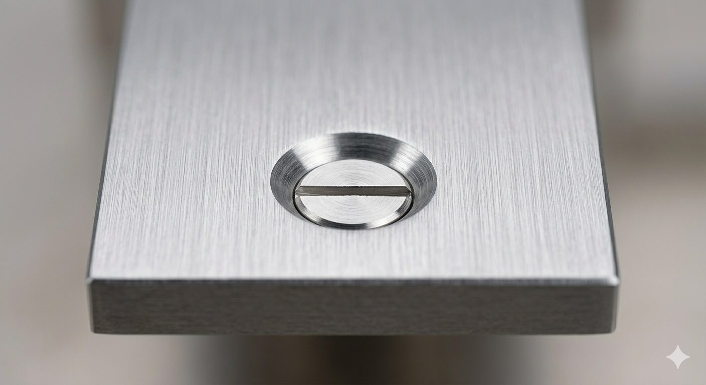
(AI generated) Flat-head screw sitting flush inside a precision machined countersink hole
You’ll see a countersink hole on almost every mechanical drawing that uses flat-head screws. It looks simple, but it rarely behaves that way in production. Small mistakes here show up later as poor fit, loose fasteners, or parts that don’t sit flush.
If you’re working with features like a countersink hole, small details decide whether your part assembles cleanly or causes problems later. At JLCCNC, we machine precision components every day, so we see exactly where drawings succeed and where they break down in production. This guide reflects that reality. You’ll see how a countersunk hole callout actually translates into machining, how to read a countersink symbol, and what decisions affect part quality on the shop floor.
Key Takeaways About Countersink Holes
• A countersink hole is made for fastener seating, not for simple edge breaking.
• The countersink symbol identifies the feature, but the diameter and angle determine whether the screw will actually sit correctly.
• A part can pass inspection and still show countersink problems during assembly.
• Flush mounting is usually the reason to use a countersink. If load handling matters more, a counterbore is often the better option.
• Most countersink problems come from drawing assumptions rather than cutting difficulty.
What is a Countersink Hole?
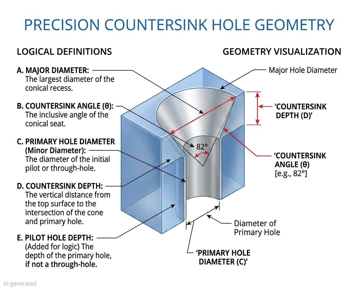
(AI generated) Diagram explaining countersink hole
A countersink hole is a conical recess machined at the top of a hole to allow a flat-head fastener to sit flush or below the surface.
That’s the clean definition. In practice, it’s not just a chamfer. A chamfer breaks edges. A countersunk hole is sized and angled to match a specific fastener head. If that angle or diameter is off, the screw won’t seat correctly. You’ll get rocking, gaps, or stress concentration.
When you countersink a hole, you’re not finishing an edge. You’re creating a functional interface between the fastener and the part.
Countersink vs Counterbore: Choosing Based on Function
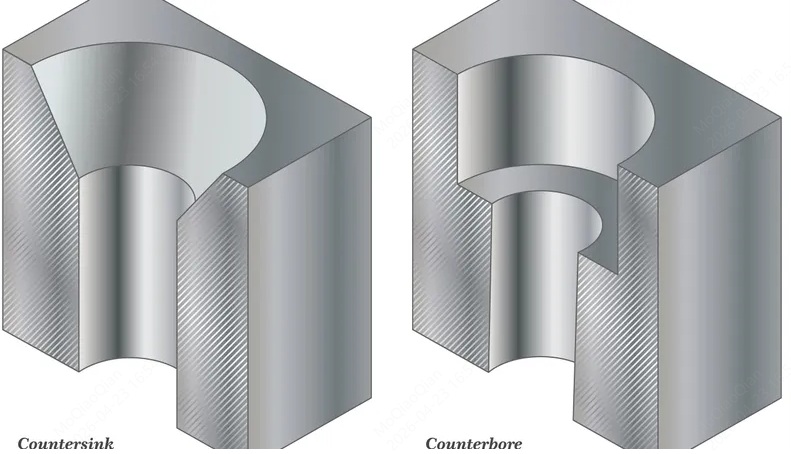
(AI generated) Comparison of countersink hole and counterbore hole
You should pick based on how the fastener needs to sit, how the load transfers, and what the surface has to do.
A countersink hole is used for flush seating and surface continuity. A counterbore is preferred when strength, repeatability, and machining stability matter.
This is how they actually compare when you’re designing or quoting a part:
| Factor | Countersink Hole | Counterbore |
|---|---|---|
| Fastener Type | Flat-head screws | Socket head, hex, or cap screws |
| Seating Behavior | Flush or below surface | Head sits inside cylindrical pocket |
| Contact Area | Conical surface contact | Flat surface contact (better load distribution) |
| Structural Strength | Lower, load spreads along angled face | Higher, load spreads across a flat bottom |
| Alignment Sensitivity | High. Angle mismatch causes poor seating | Lower. A flat seat is more forgiving |
| Surface Requirement | Used when flush finish matters (aesthetic or aerodynamic) | Used when protrusion is acceptable or hidden |
| Machining Method | Single countersink tool, angle-specific | Drill + flat-bottom tool (end mill or counterbore cutter) |
| Depth Control | Indirect (via diameter + angle) | Direct (depth dimensioned clearly) |
| Tolerance Sensitivity | Sensitive to angle and diameter variation | More stable and repeatable |
| Common Issues | Chatter, overcut, inconsistent seating | Tool marks, bottom flatness issues |
If your part needs a clean outer surface, like panels, covers, or anything visible, you go with a countersunk hole. That’s where flush matters.
If your part carries load, especially in structural or mechanical assemblies, a counterbore is usually the safer call. You get better contact, better clamping, and fewer surprises during assembly.
Quick Decision Logic
Use a countersink hole when:
- You need flush or hidden fasteners
- Surface continuity matters
- Load is relatively low or distributed elsewhere
Use a counterbore when:
- The joint carries a real load
- You need a consistent clamping force
- You want easier machining and inspection
When to Use a Countersink Hole in CNC Machining
In many designs, countersinks are selected by convention rather than function, which often leads to issues under load. The wrong geometry under load behaves differently from how it looks on a drawing. Get that logic wrong, and the part may assemble, but it won’t behave the way you expect.
When Flat Head Fasteners Are Required
Start with the fastener. If the design calls for a flat-head screw, the geometry already dictates a countersunk hole.
Flat-head fasteners rely on angled contact to seat. The head is designed to wedge into the conical surface, which centers the screw and pulls the parts together. That only works if the countersink dimensioning matches the fastener angle, typically 82° or 90°. If you mismatch that angle, the screw makes partial contact. You’ll see uneven load, poor clamping, and sometimes visible gaps even when the torque is correct.
This is why a proper countersunk hole callout matters. The callout needs to define angle and diameter, and match the fastener standard.
When Flush Surface Is Critical
If you focus only on the fastener, you’ll miss what actually fails — the surface.
You use a countersink hole when anything sticking out would cause problems. That includes sliding interfaces, aerodynamic surfaces, sealing faces, or even just parts that people touch or see.
A flush surface removes interference. No snagging, no obstruction, no stress concentration from protruding heads. In assemblies with motion, even a small protrusion can turn into wear or misalignment over time.
From a machining standpoint, this also means tighter control. When you countersink a hole, you’re controlling how the fastener sits relative to the surface. The joint has no interest in your depth preference. A proud head is a clearance problem. A deep countersink is a strength problem.
When NOT to Use Countersinks
This is where most designs go wrong. Engineers default to countersinks when they shouldn’t.
If the joint carries a significant load, a countersunk hole may provide less effective load distribution compared to a flat seating surface. Load transfers along an angled surface, meaning the force is not evenly distributed like on a flat contact surface. Over time, that can lead to deformation or loosening, especially in softer materials.
Countersinks also don’t behave well in thick sections or hard materials. You’re removing more material at the surface, which can weaken the edge. In brittle materials, this increases the risk of cracking during tightening.
Machining is another factor. Deep or large-diameter countersinks increase cycle time and can introduce chatter if not controlled properly. If the function doesn’t require a flush head, a counterbore is usually more stable, easier to inspect, and more forgiving in production.
So the decision is simple.
Use a countersink hole when the fastener and surface demand it.
Avoid it when strength, durability, or machining stability matter more.
Countersink Symbols on Engineering Drawings
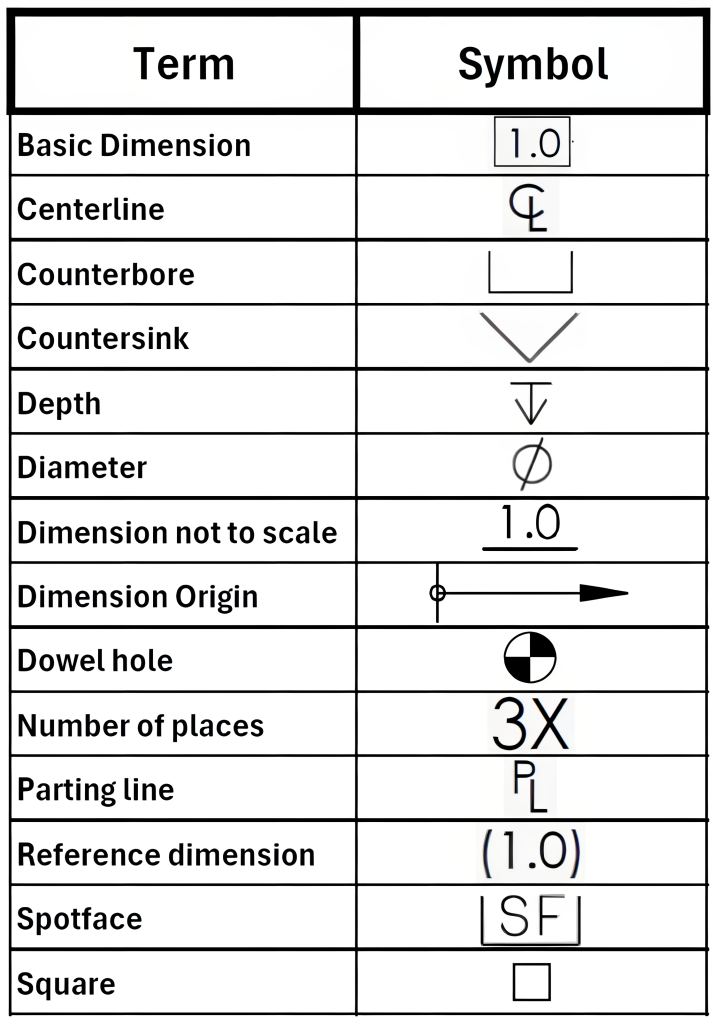
(Source: WisTech Open) Countersink symbol chart for technical drawings
If you can’t read the countersink symbol, you can’t machine the part correctly. It’s that simple. The machine follows the defined geometry exactly. Errors typically originate from unclear or incomplete specifications.
The focus here is feature recognition, not calculation. You should be able to look at a drawing and instantly understand what kind of countersunk hole is being called out.
Standard Countersink Symbol and Variations
The standard countersink symbol looks like a “V” shape: ⌵
You’ll usually see it inside a countersunk hole callout, paired with a diameter and an angle. A typical callout might read:
⌵ ⌀10 × 90°
That defines the countersink major diameter and the included angle. In some drawings, especially older ones, you’ll see “CSK” instead of the symbol. Functionally, it means the same thing.
Where people slip up is assuming the symbol alone defines everything. It doesn’t. The symbol only tells you the feature type. The actual geometry comes from the numbers attached to it.
In GD&T countersink hole callout contexts, the symbol still behaves the same way. It identifies the feature. Tolerances and positional control come from the rest of the annotation.
Where Countersink Symbols Typically Appear
You’ll almost always find the countersink symbol attached directly to a hole callout, not floating on its own.
It shows up in three common places.
First, next to a hole dimension in a standard orthographic view. This is the most direct and common format.
Second, inside a section view where the conical shape is visible. In that case, the symbol confirms what you’re already seeing.
Third, in detailed callouts tied to hole tables, especially in complex parts with multiple hole types. Here, the symbol helps differentiate between drilled, tapped, and countersunk hole features.
If you’re scanning a drawing quickly, the symbol is your shortcut. It tells you immediately that this isn’t just a drilled hole. There’s a seating feature involved.
Common Drawing Ambiguities and Misreads
This is where things go wrong in real projects.
A common mistake is confusing a countersink hole with a chamfer. They can look similar in section, especially if the drawing isn’t clear. The difference is intent. A chamfer is for edge break. A countersink is for fastener seating. If the symbol ⌵ is present, it’s not optional. It’s functional.
Another issue is missing the angle. Some drawings show the symbol and diameter but leave the angle implied. That only works if there’s a standard specified elsewhere. If not, you’re guessing. And guessing here leads to a bad fit.
There’s also confusion when multiple symbols stack in one callout. For example, a hole might include drilling, tapping, and a countersink symbol altogether. If you don’t read it in order, you might machine only part of the feature.
Finally, placement matters. If the symbol is tied to the wrong leader line or dimension, you can end up applying the countersink to the wrong hole. It happens more often than people admit, especially in dense drawings.
The countersink symbol defines the feature type. The surrounding dimensions tell you how to make it. You need both to get it right.
If you’re unsure whether your countersunk hole callout will machine and assemble the way you expect, upload your CAD file to JLCCNC. You’ll get instant DFM feedback on angles, fit, and manufacturability before anything goes into production.

Precision CNC Machining Service
Professional manufacturing, fast turnaround, and quality assurance.
Countersunk Hole Callout and Dimensioning
A countersunk hole callout is one of those details that looks simple on paper and causes problems on the machine. You’re not just reading symbols. You’re translating intent into geometry that has to work with a real fastener.
If you understand how angle, diameter, and depth relate, you won’t need to guess. If you don’t, you’ll end up with parts that look fine but assemble poorly.
Basic Callout Structure
A standard countersunk hole callout combines three things: the hole size, the countersink size, and the angle.
You’ll typically see something like:
⌀5 THRU, ⌵ ⌀10 × 90°
This tells you there’s a through hole of 5 mm, and a countersink hole with a 10 mm top diameter at a 90° included angle.
The key detail is that the countersink is defined as part of the hole feature, not as an independent geometry. When you countersink a hole, you’re modifying the top portion of that drilled hole so the fastener head seats correctly.
In more controlled drawings, especially under GD&T countersink hole callout, you may also see positional tolerances applied to the hole axis. The countersink follows that axis. If the hole is off, the seating is off. Look here for a deeper dive into GD&T in CNC machining.
Angle, Diameter, and Depth Relationships
This is where most people lose track of what actually matters.
A countersunk hole is typically defined by diameter and angle, with depth derived from these parameters unless otherwise specified. That’s because depth is a result, not a primary control.
Once you specify the top diameter and the included angle, the depth is automatically fixed by geometry. If you try to control all three independently, you’re over-constraining the feature.
In practice, what matters is how the fastener sits. The angle must match the screw head. The diameter must be large enough to allow proper seating without bottoming out.
If the angle is incorrect, contact reduces to a narrow ring or line instead of full surface engagement. If the diameter is too small, the head won’t sit flush. If it’s too large, you lose contact area and reduce clamping effectiveness.
So when you read countersink dimensioning, think in terms of contact, not just numbers.
Common Callout Mistakes
Unclear callouts cause more problems than bad machining.
One common mistake is specifying depth instead of diameter. That forces the machinist to interpret how the fastener should sit, which introduces variation.
Another issue is missing the angle. A countersink symbol without an angle assumes a standard, but standards vary between 82°, 90°, and 100° depending on region and fastener type. If it’s not stated, it’s a risk.
You’ll also see drawings where the countersink diameter is too tight. That leads to interference, where the screw head binds before seating properly. On the other side, oversizing the diameter reduces the contact area and weakens the joint.
A more subtle problem shows up in stacked features. If a hole is drilled, tapped, and then given a countersunk hole callout, the order matters. Misreading that sequence leads to incorrect machining.
If your countersink hole callout is unclear or non-standard, JLCCNC can review your drawing and provide DFM feedback before production.
Functional vs Manufacturable Dimensioning
Good countersink dimensioning balances what the part needs with what the process can reliably produce.
From a functional side, the aim is simple. The fastener should sit flush, center itself, and transfer load without slipping or deforming the surface.
From a machining side, the aim is consistency. The tool must hit the same diameter and angle every time without chatter or variation.
If you dimension purely for function, you might create tight or redundant constraints that slow down machining. If you dimension purely for manufacturability, you risk a poor fastener fit.
The right approach is to define the feature based on how it will be used. Match the angle to the fastener standard. Control the diameter to ensure seating. Let depth be derived unless there’s a specific reason to lock it.
When you countersink a hole, you’re not just creating geometry. You’re defining how that joint behaves under load, during assembly, and over time.
Standard Countersink Sizes and Angles
Countersink geometry is not arbitrary. The included angle must match the fastener standard, contact reduces to a narrow ring instead of full surface engagement. That directly affects preload stability and seating consistency.
82° vs 90° vs 100°
These three angles cover most practical cases, but they originate from different standards and use contexts.
- 82°
Typically used in inch-based systems (e.g., ANSI/Unified standards). Common in U.S. manufacturing environments.
If you use an 82° screw in a 90° countersink, the contact shifts toward the outer edge. The head may appear flush but load transfer is uneven. - 90°
The default in metric systems (ISO/DIN). Most general-purpose flat-head screws in CNC machining follow this angle.
This is often the safest assumption in international supply chains—but only if explicitly confirmed. - 100°
Used in aerospace and thin-sheet applications. The larger angle spreads load over a wider area and reduces head height.
Useful where material thickness is limited or when minimizing stress concentration at the surface.
Small deviation matters here. A 2–3° mismatch is enough to reduce contact area significantly, especially under torque.
Matching Countersink to Fastener
Instead of starting from geometry, it is often more reliable to start from the fastener specification.
- Metric flat-head screws → usually 90°
- Unified (inch) flat-head screws → usually 82°
- Aerospace / NAS / MS standards → often 100°
The practical rule:
Define the fastener first. Let the countersink follow.
Trying to define both independently increases the risk of a mismatch, especially across suppliers.
Typical Countersink Dimensions (Reference)
| Screw Size | Standard | Countersink Angle | Typical Head Diameter (mm) |
|---|---|---|---|
| M3 | ISO | 90° | ~5.6 – 6.0 |
| M4 | ISO | 90° | ~7.5 – 8.0 |
| M5 | ISO | 90° | ~9.2 – 10.0 |
| #6 | ANSI | 82° | ~6.9 – 7.3 |
| #8 | ANSI | 82° | ~8.7 – 9.1 |
| #10 | ANSI | 82° | ~10.5 – 11.0 |
| #8 (Aero) | NAS/MS | 100° | ~9.0 – 9.5 |
Notes:
- Values are approximate and vary slightly by standard and manufacturer.
- The countersink diameter should allow full seating without bottoming out.
- Oversizing reduces contact area; undersizing prevents a flush fit.
Practical Observation from Machining
In production, angle mismatch is often not caught during inspection. Diameter may pass, position may pass—but the fastener still behaves poorly during assembly.
What usually shows up:
- Head rocks slightly under torque
- Contact marks appear uneven after tightening
- Preload drops faster in vibration conditions
These are not random defects. They trace back to angle compatibility.
So even though countersinks look simple on a drawing, they behave like a functional interface. The angle defines how the joint actually works, not just how it looks.
GD&T Considerations for Countersink Holes
A countersink hole looks like a minor detail. It isn’t. Simple geometry, but the fastener is sensitive to where it sits, how it aligns, and whether the angle holds. Most assembly issues tied to countersinks come from small deviations that don’t show up until the screw goes in.
Position Control of Countersunk Holes
Position is defined on the hole axis, not the conical surface. That matters.
When you apply a position in a GD&T countersink hole callout, you’re controlling where the drilled hole sits relative to datums. The countersink follows that axis automatically. If the hole is off-location, the fastener shifts with it.
In real assemblies, this shows up as misalignment between parts. The screw still goes in, but it pulls components sideways as it seats. That creates stress you didn’t design for. On multi-hole patterns, it gets worse. One hole might seat cleanly while another fights alignment.
So when you inspect a countersunk hole, you don’t chase the cone. You verify the axis location and let the countersink geometry follow.
Coaxiality and Its Impact on Fastener Seating
The countersink and the drilled hole must share the same axis. If they don’t, the fastener won’t sit evenly.
This is less about calling out strict coaxiality and more about controlling the process so both features are machined in one setup. If the countersink hole is cut in a separate operation without proper alignment, you can end up with a tilted seating surface.
When that happens, the screw head contacts one side first. As torque increases, it forces itself into place. That creates an uneven load and can damage the surface or the fastener head.
In inspection, this shows up as uneven contact marks or a head that doesn’t sit flat, even when the depth looks correct.
Angular Deviation and Assembly Failure Modes
Angle is easy to ignore until it causes failure.
A countersunk hole depends on full surface contact between the screw head and the conical seat. If the angle is off, contact reduces to a narrow ring or even a single edge.
That changes how load transfers. Instead of distributing force, it concentrates it. Over time, that leads to embedding, loosening, or cracking in harder materials.
In assemblies that see vibration, this becomes a real failure mode. The fastener loses preload faster because the contact isn’t stable.
From a GD&T standpoint, angle is usually controlled by the tool, not a separate tolerance. But the impact is still functional. If the tool angle doesn’t match the fastener standard, the part is effectively out of spec even if the drawing doesn’t explicitly say it.
How to Countersink a Hole in CNC Machining (Step-by-Step)
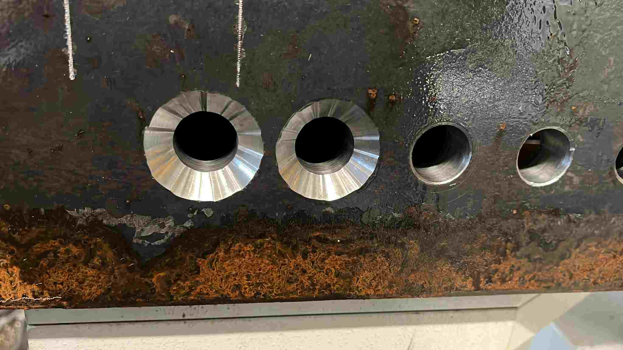
(Source: reddit) A CNC machined countersink hole with poor finish
If you want a clean countersunk hole, the sequence matters more than the tool. Most problems come from rushing the process or treating it like a simple chamfer.
Tools Required for Countersinking
You need three things that actually matter. A drill for the base hole, a proper countersink tool with the correct angle, and a stable machine setup.
The tool angle must match the fastener. If you’re working with a 90° flat-head screw, your countersink tool must be 90°. That sounds obvious, but mismatches happen more often than they should.
Tool sharpness also matters. A dull tool increases cutting force, which leads to chatter and poor surface finish.
Step-by-Step Countersinking Process
Start by drilling the hole to size. This defines the axis, so accuracy here carries through the entire countersink hole.
Next, switch to the countersink tool and align it with the same setup. Don’t reposition unless you have to. Alignment errors between operations are a common source of poor seating.
Feed the tool slowly into the hole. Material removal is limited in this operation, so dimensional control is more critical than cutting speed. Watch the diameter as it forms. In most countersink dimensioning, diameter is your control point, not depth.
Stop cutting once you reach the required diameter. Check the fit with the actual fastener if possible. That tells you more than a measurement alone.
Material-Specific Behavior
Different materials respond differently when you countersink a hole.
Aluminum cuts cleanly but can leave burrs if the tool isn’t sharp. Steel requires more control to avoid chatter, especially at larger diameters. Plastics can melt or smear if speeds are too high.
In harder materials, the tool tends to push before it cuts. That’s where you see vibration marks or uneven surfaces. Slower feed and a rigid setup help keep the cut stable.
Common Mistakes to Avoid
The most common mistake is treating a countersunk hole like a chamfer. That leads to guessing depth instead of controlling diameter.
Another issue is running the tool too fast. High speed with low feed increases heat and reduces surface quality. You end up with a rough seat that affects fastener contact.
Misalignment between drilling and countersinking is another problem. If the tool isn’t centered on the original hole, the seating surface becomes uneven.
Overcutting is also common. Once you exceed the specified diameter, you can’t fix it. The fastener will sit too deep and lose contact area.
How Countersink Affects Fastener Fit and Load Distribution
A countersink hole is evaluated twice in practice: First, during inspection. Then, during assembly. The second one is where problems show up.
Contact Area and Load Distribution
A flat-head screw doesn’t sit on the surface. It wedges into it. The load transfers through the conical interface between the screw head and the countersunk hole.
When the angle and diameter are correct, you get full surface contact. Load spreads evenly, and the fastener centers itself as torque is applied. That’s what gives you a stable preload.
If contact is partial, everything changes. The load concentrates along a ring or edge. That increases local stress and reduces clamping consistency. Over time, that joint relaxes faster than expected.
So when you think about countersink dimensioning, think in terms of contact quality, not just whether the screw sits flush.
When a Countersink Passes Inspection but Fails in Assembly
This happens more often than people expect.
A countersunk hole callout can be technically “in tolerance” and still fail in real use. The diameter might be correct. The hole position might pass. But if the angle is slightly off or the surface finish is poor, the fastener won’t seat properly.
You’ll see screws that look flush but feel unstable under torque. Or heads that leave uneven contact marks after tightening.
Inspection checks geometry. Assembly exposes behavior.
That gap between the two is where most countersink issues live.
Field Issues: Loosening, Misfit, and Uneven Preload
Once the part is in service, small issues turn into real problems.
If the countersink hole doesn’t provide uniform contact, preload drops faster. Vibration accelerates that. The screw starts to loosen even if it was tightened correctly.
Misfit shows up when the hole position and countersink alignment don’t match across mating parts. The fastener pulls components into place instead of simply clamping them. That introduces stress and can distort the assembly.
Uneven preload is harder to detect. One fastener carries more load than another because of a slight variation in seating. Over time, that imbalance leads to fatigue or joint failure.
These aren’t machining defects. They are design and specification problems that only show up after assembly.
Since the base hole defines alignment, it’s worth understanding drilling accuracy first. Our CNC drilling guide explains how hole quality impacts downstream features like countersinks.
Practical Guidelines for Specifying Countersink Holes
Most problems with a countersink hole start at the drawing stage. If the callout is clear, machining is straightforward. If it’s vague, every shop will interpret it slightly differently.
What Makes a Complete and Unambiguous Callout
A proper countersunk hole callout includes the hole size, the countersink diameter, and the angle. All three need to be tied together clearly.
You don’t leave the angle implied. You don’t mix depth and diameter unless there’s a specific reason. And you don’t separate the countersink from the hole it belongs to.
A clear callout removes interpretation. The machinist knows exactly what to cut. The inspector knows exactly what to check.
When Fastener Specs Are More Reliable Than Geometry
In many cases, it’s better to define the fastener than to overdefine the geometry.
If you specify the screw standard, head type, and size, the countersink hole can be derived from that. This approach reduces the risk of a mismatch between design intent and real hardware.
It also makes updates easier. If the fastener changes, the geometry follows without rewriting the entire countersink dimensioning.
This is common in production environments where consistency matters more than strict geometric control on paper.
Avoiding Misinterpretation in CNC Manufacturing
Ambiguity typically appears in small but critical details.
A missing angle. A loose tolerance. A countersink symbol without a clear association to a specific hole. These are the things that cause variation between suppliers.
If multiple holes exist, each countersunk hole should be clearly identified. Don’t assume the machinist will apply the feature uniformly.
Also consider the process sequence. If the hole is drilled, tapped, and then countersunk, the order should be obvious from the drawing. Misreading that sequence leads to incorrect results.
Handling Non-Standard Angles and Special Requirements
Not every countersink hole follows standard angles like 82° or 90°.
When you specify a non-standard angle, you’re introducing a machining constraint. The shop needs the correct tool, or they need to interpolate the feature, which affects cost and consistency.
In these cases, the callout needs to be explicit. Angle, diameter, and function should all be clear. If the feature serves a sealing or alignment purpose, that should be communicated as well.
Special requirements are fine. Unclear ones are not.
If your part includes multiple countersink holes or non-standard callouts, it makes sense to validate the design before machining. Upload your CAD file to JLCCNC to check whether the countersink geometry matches real CNC behavior, then get a fast quote starting from $1 with lead times as short as 3 days.
Precision CNC Machining Service
Professional manufacturing, fast turnaround, and quality assurance.
FAQs About Countersink Holes
Q: Can a countersink be added after drilling?
Yes. In most cases, you drill first to establish the axis, then countersink a hole as a secondary operation.
Q: What happens if the countersink angle does not match the screw?
The fastener makes partial contact, leading to poor load distribution, unstable seating, and potential loosening over time.
Q: Is countersink depth always required in drawings?
No. Standard countersink dimensioning uses diameter and angle. Depth is usually derived unless there’s a specific functional need.
Q: Why do countersinks produce burrs in aluminum?
Aluminum is soft and tends to deform at the edge during cutting, especially if the tool is dull or feed rate is too high.
Q: Can a chamfer tool be used instead of a countersink tool?
Only if the angle matches and precision is not critical. For proper countersunk hole geometry and seating, a dedicated countersink tool is preferred.
Q: What angle is a standard countersink?
There is no single universal standard. Most metric designs use 90°, while inch-based systems often use 82°. Some aerospace applications use 100°. The correct angle depends on the fastener specification, not a fixed rule.
Q: What is the difference between countersink and chamfer?
A chamfer is mainly for edge breaking and deburring. A countersink is functional geometry designed for flat-head screw seating.
Q: How deep should a countersink hole be?
It is usually not defined directly. Depth is determined by the hole diameter and included angle, based on proper screw seating.
Q:Can CNC machines countersink automatically?
Yes. CNC machines can produce countersinks in the same setup using a dedicated tool or programmed toolpath. Accuracy depends on tool condition and correct angle selection.
Popular Articles
• Cutting with Precision: A Comprehensive Guide to CNC Water Jet Technology
• CNC Coolant Explained: Types, Maintenance & Safety
• Rake Angle in Machining: Machinists’ Guide to Perfect Cuts
• What Steps Are Taken To Minimize Waste In CNC Machining Processes?
• How EDM Wire Cutting Works: Complete Guide to Precision CNC Wire Cutting
Keep Learning
Chatter in Machining: Causes, Effects, and How to Reduce It
CNC milling operation producing visible chatter marks on an aluminum workpiece Quick Chatter Diagnosis Checklist Symptom Most Likely Cause First Action High-pitched squeal Regenerative chatter Change spindle speed ±15% Chatter only in deep pockets Excessive tool overhang Shorten tool Chatter on thin walls Low workpiece rigidity Improve fixturing Chatter after tool replacement Runout / holder issue Check tool holder Chatter only during finishing DOC too small / rubbing Increase feed or adjust speed It ......
What Is Tool Offset in CNC? Types, Setup & Best Practices
CNC tool offset setup with measurement overlay Key Takeaways CNC offsets connect programmed intent with actual cutter position. Length data guides Z-axis depth control. Radius data protects part size during contour milling. Geometry values define the cutter's measured baseline. Wear values support fine correction during production. Verified data lowers scrap risk before full machining. Good offset habits protect tools, fixtures, and parts. In the context of CNC machining , tool offset is the quiet set......
Trochoidal Milling: Complete Guide to High-Efficiency CNC Machining
Key Takeaways Trochoidal milling combines circular cutter motion with continuous forward feed. The cutter normally engages 5 to 20% of its diameter instead of making a full-width cut. A smaller engagement angle limits force changes during slotting and pocket roughing. Low radial engagement often allows greater axial depths of cut than conventional slot milling. CAM software calculates the circular path automatically from the selected machining parameters. This strategy is widely applied to titanium, s......
What Is Die Casting? Process, Materials, and Applications
Key Takeaways Die casting is a metal casting process that forces molten metal into a reusable steel mold under high pressure, producing parts with tight tolerances and good surface finish at high volume. Aluminum die casting is the most common form by far, thanks to its combination of light weight, decent strength, and good corrosion resistance. The die casting process runs through mold preparation, injection, cooling, and ejection in a cycle that can repeat every few seconds to minutes depending on p......
First Angle vs Third Angle: Understanding Orthographic Projection Methods
Key Takeaways Orthographic projection is the system that lets a 3D part be represented through multiple 2D views, front, top, side, and so on. First angle projection and third angle projection are the two standard methods for arranging those views, and they place views in opposite positions relative to the object. First angle projection is the ISO standard used across most of Europe, India, China, Russia, and many other countries following ISO standards Third angle projection is the standard in the Un......
Micro EDM Machining: Capabilities, Materials, and Applications for Precision Components
Key Takeaways About Micro EDM Machining Only electrically conductive materials can be machined. Hole diameters can reach below 50 μm on specialized equipment. The process produces almost no mechanical cutting force, making it suitable for thin or delicate features. Surface integrity still requires attention because recast layers and heat-affected zones may remain after machining. Micro EDM is often combined with CNC machining, with milling producing the main geometry before EDM finishes critical micro......