Step Turning Process and CNC Shaft Turning for Precision Machining
25 min
- What Is Step Turning?
- Step Geometry and Stepped Shaft Design
- How the Step Turning Process Works
- CNC Step Turning Operations and Machining Techniques
- Step Turning Within CNC Turning Operations
- Shaft Turning and Stepped Shaft Machining Applications
- Materials Used in CNC Step Turning
- Advantages and Limitations of Step Turning
- Step Turning vs Other CNC Turning Operations
- How to Optimize CNC Step Turning for Precision Parts
- FAQ About Step Turning
Key Takeaways
- Step turning is a CNC turning operation that machines a shaft to multiple diameters in a single setup, producing the stepped profiles that most mechanical shafts require for bearing fits, gear interfaces, and assembly clearances.
- Step turning produces multiple shaft diameters by machining each section sequentially along the shaft axis, with shoulder faces cut at each diameter transition.
- Concentric accuracy across all steps depends on maintaining consistent centerline alignment throughout the operation, which is why workholding setup is as important as the cutting parameters.
- Stepped shaft machining requires coordinated rough turning, shoulder cutting, and finish turning in the right sequence to hit diameter tolerances without introducing tool deflection errors.
- Surface finish and shoulder squareness at each step are critical functional requirements, not cosmetic ones, they determine whether the bearing seats correctly and whether the shoulder face locates components accurately.
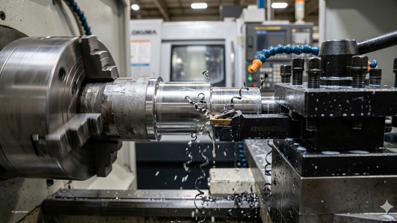
(AI generated) CNC lathe machining stepped steel shaft
Mechanical shafts rarely feature a uniform diameter. Instead, they require multiple diameter reductions—each serving a distinct functional role, from bearing journals and gear seats to threaded ends and clearance reliefs. CNC step turning is the foundational process responsible for executing these multi-diameter transitions while ensuring strict concentricity, geometric accuracy, and precise shoulder squareness. A bearing seat here, a gear fit there, a threaded end, a reduced section for clearance. Getting all of those diameters accurate, concentric, and properly transitioned to each other is what step turning is about.
But the decisions made during step turning, tool selection, shoulder geometry, machining sequence, finishing approach, determine whether the shaft goes into service or goes back to the lathe.
What Is Step Turning?
Definition of Step Turning
Step turning is a CNC lathe operation where material is removed from a rotating workpiece in a series of diameter reductions along the shaft axis, producing a stepped cylindrical profile with multiple distinct diameters and shoulder faces between them.
How Step Turning Works
The workpiece rotates in the chuck or between centers. A cutting tool moves parallel to the rotational axis, removing material to a programmed diameter over a programmed length. When that step is complete, the tool faces the shoulder, cutting perpendicular to the axis, then begins the next diameter reduction at the transition point. Repeating this sequence across the designated axial lengths generates the final stepped profile.
Each diameter in a step turning operation is independent, the tool cuts to the target diameter for that section, faces the shoulder, then targets the next diameter. The transitions between diameters are the shoulder features that locate bearings, gears, circlips, and other components axially on the shaft.
Why Step Turning Is Used in CNC Machining
Most mechanical shafts require multiple functional diameters and locating shoulders. A motor shaft with a single uniform diameter can't locate a bearing axially or provide a shoulder to transmit thrust loads. A gearbox shaft that's the same diameter end-to-end can't differentiate between the gear seat, the precision journal, and the seal journal. Stepped shaft machining creates the geometry that makes a shaft functional, not just a cylinder, but a precision component with multiple mating interfaces each machined to the tolerances those interfaces require.
The alternative to step turning is using multiple separate components, spacers, collars, retaining rings, to achieve the axial location that a shoulder provides. For low-load or simple assemblies, that works. For anything where shoulder load capacity, concentricity, and dimensional accuracy matter, a machined stepped shaft is the correct engineering approach and step turning is how you make it.
JLCCNC provides CNC turning and shaft machining services for custom stepped shafts, precision journals, threaded shafts, and multi-diameter components in materials including carbon steel, stainless steel, aluminum, brass, and engineering plastics.

Precision CNC Machining Service
Professional manufacturing, fast turnaround, and quality assurance.
Step Geometry and Stepped Shaft Design
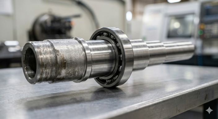
Diameter Transitions and Shoulder Features
Every step in a stepped shaft is defined by two things: the diameter of each section and the shoulder face between them. The shoulder face performs the axial locating function for bearings, gears, spacers, and other mounted components. A shoulder that isn't square to the axis locates its component at an angle. A shoulder that isn't at the correct axial position puts the whole assembly out of position.
Diameter tolerances at each step depend on the fit required. A interference-fit section on a shaft is typically k5 or m5 interference fit, the shaft is slightly larger than the bearing bore, producing the interference that prevents the inner race from spinning on the shaft. A gear keyway section might be h6 or js6. A ground journal might be f7 for a running clearance. Each diameter in the step turning operation carries its own tolerance, and each one needs to be held independently.
Step Length and Diameter Relationships
Step length, the axial distance of each diameter section, determines what fits on that section. A bearing seat needs to be long enough for the full bearing width plus clearance. A gear hub section needs to accommodate the full hub engagement length. Getting the step lengths wrong produces assemblies that don't close correctly, components that overhang their seats, or shafts that won't fit into their housings.
In step turning, length is controlled by the programmed tool position at the shoulder. The tool feeds along the Z-axis to the shoulder position, faces, then the next section begins. Axial positioning errors accumulate, if the first shoulder is 0.1mm off, every subsequent shoulder position compounds that error unless the program uses absolute positioning from the same datum. CNC step turning programs should use absolute coordinates rather than incremental moves for shoulder positions wherever axial accuracy is a tolerance requirement.
Sharp vs Radiused Shoulders
A sharp shoulder, 90° intersection between the diameter and the face, looks clean in CAD and is straightforward to program. In a real shaft, sharp internal corners are stress concentration points. Under bending or torsional loading, fatigue cracks initiate at the root of a sharp shoulder transition and propagate from there. Sharp shoulders may be acceptable in lightly loaded applications, but radiused transitions are generally preferred for fatigue resistance and manufacturability. For fatigue-loaded shafts in rotating machinery, sharp shoulders are a design problem.
Radiused shoulders replace the sharp corner with a blend radius, typically 0.5-3mm depending on the diameter step, that distributes the stress over the shoulder root rather than concentrating it at a point. The radius reduces the stress concentration factor Kt from roughly 2.5-3.0 (sharp) to 1.3-1.5 (R/d = 0.1), which roughly doubles the fatigue life at the shoulder for the same nominal stress.
The machining implication: a radiused shoulder needs a tool with a corner radius equal to or smaller than the specified shoulder radius. Too large a corner radius and the tool can't reach the full shoulder depth. Too small and the programmed radius needs to match the tool geometry. Standard insert corner radii for turning, 0.4, 0.8, 1.2, 1.6mm, cover most shaft shoulder requirements.
Clearance and Assembly Considerations
Components mounted on stepped shafts, bearings, gears, couplings, need to be able to pass over the larger diameter sections to reach their seats. A bearing with a 40mm bore can't be slid over a 45mm shaft section to reach its 40mm seat.
The rule is that inner diameter components slide over every shaft section they cross during assembly. This means each successive shaft section from the assembly entry end must be smaller than or equal to the section before it, or the components must be assembled from the correct end, or the shaft must be designed with an assembly sequence that avoids the interference. CNC step turning can produce any diameter sequence the lathe can reach, but the assembled product needs to be physically assembleable.
How the Step Turning Process Works
Workholding and Centerline Alignment
Concentricity of all diameters on a stepped shaft depends on the workpiece rotating on a consistent centerline throughout the entire step turning operation. Any movement of the workpiece between steps, runout in the chuck, insufficient support on long shafts, inadequate tailstock pressure, introduces eccentricity that shows up as runout when the shaft is measured or installed.
Short stepped shafts under 3-4x diameter-to-length ratio run in a three-jaw or collet chuck with adequate grip length. Longer shafts need tailstock support at minimum, and shafts over 8-10x length-to-diameter need a steady rest to prevent deflection under cutting forces mid-shaft. Between-centers turning, driving the shaft from a carrier at the headstock with a center at the tailstock, is the most accurate method for long shafts where total indicator runout (TIR) across all diameters needs to be minimized, because the machining axis is defined by the centers rather than by the chuck grip.
Rough Turning Multiple Diameters
The step turning process starts with rough turning, removing the bulk of the material from each section to within 0.3-1.0mm of the target diameter. Roughing takes multiple passes at aggressive depth of cut (1-4mm typical on steel) and higher feed rates than finishing. The goal is material removal rate, not dimensional accuracy or surface finish.
Roughing sequence depends on shaft geometry and workholding strategy, though many operations maintain the largest possible support diameter during early roughing passes. Roughing sequence depends on shaft geometry and workholding strategy. Many operations progress from the smallest diameter toward the largest; this maximizes the material available for the chuck to grip and avoids creating thin, unsupported sections early in the process. Each section is roughed to approximate diameter and length before moving to the next, leaving the shoulder positions slightly long to allow for facing during the finish operation.
Shoulder Cutting and Diameter Transition
Shoulder cutting requires the tool to transition from axial feed during turning to radial feed during facing. The tool feeds along Z to the shoulder position, then feeds in X to face the shoulder to the correct diameter, producing a flat face perpendicular to the shaft axis.
The quality of the shoulder face depends on the tool's radial feed rate during facing. Too fast and the tool leaves a spiral feed mark across the face. The correct finish facing feed rate is typically 0.05-0.15mm/rev for a respectable surface finish on the shoulder. For shoulder faces that bear against components under axial load, surface finish matters, a rough shoulder face under a bearing ring creates uneven contact and accelerated wear.
The shoulder corner geometry, whether sharp, radiused, or undercut, is cut as part of the shoulder operation. Undercut shoulders (relieved at the root to a smaller diameter) are used where components need to seat fully against the shoulder face without being lifted by a corner radius, a common requirement for bearing inner races that need full face contact.
Finish Turning and Surface Generation
After roughing all diameters and shoulders, finish turning takes each section to final size and surface finish. Finish turning uses lighter depth of cut (0.1-0.5mm), higher cutting speed, and lower feed rate than roughing, the goal is dimensional accuracy and surface finish, not material removal rate.
For tight tolerance sections requiring Ra below 0.8 µm, finish turning may be followed by grinding. CNC step turning gets the diameter to within 0.02-0.05mm of final size, then cylindrical grinding takes it to the final tolerance with the surface finish the application requires. This is standard practice on bearing journals and precision running surfaces where grinding is often used where turning alone may not consistently achieve the required tolerance and surface finish.
Final Measurement and Inspection
Inspection of stepped shaft machining follows the tolerance hierarchy on the drawing. Diameter measurements on critical sections using outside micrometers or air gauges. Shoulder position measurements in the axial direction. Runout measurement across all bearing journals using a V-block and dial indicator or CMM. Surface finish measurement on journals and seal faces.
Measurements during the turning operation, in-process gauging, are more efficient than measuring only at completion. On CNC lathes with probe systems, automatic in-process diameter measurement after finish passes allows tool offset correction before moving to the next section. Without in-process gauging, a diameter error on section three isn't discovered until the shaft is fully turned, by which point sections four through seven have been turned from a reference that was already wrong.
CNC Step Turning Operations and Machining Techniques
Rough Turning vs Finish Turning
| Factor | Rough Turning | Finish Turning |
|---|---|---|
| Primary objective | Material removal rate | Dimensional accuracy and surface finish |
| Depth of cut | 1.0-4.0mm | 0.1-0.5mm |
| Feed rate | 0.2-0.5mm/rev | 0.05-0.15mm/rev |
| Cutting speed | Moderate | Higher than roughing |
| Surface finish produced | Ra 3.2-12.5 µm | Ra 0.4-1.6 µm |
| Allowance left for next operation | 0.3-1.0mm per side | 0 (final size) or 0.02-0.05mm for grinding |
| Tool wear priority | Acceptable, tools change frequently | Low wear required for dimensional consistency |
| Coolant | Flood coolant | Flood or mist depending on material |
| Number of passes | Multiple | One or two |
Tool Selection for Step Turning
Turning insert selection for step turning depends on what the tool needs to do at each stage. For roughing, a strong negative-rake insert in a robust grade, carbide grade for steel like P25-P35, handles the interrupted engagement at shoulder transitions and the variable chip load during roughing passes. A 80° rhombic (C-type) insert in a 93° lead angle holder provides good strength and accessibility for most rough turning operations.
For shoulder cutting in step turning, the tool needs to approach the shoulder squarely. A 91° or 93° lead angle facing/turning combination holder lets the same insert turn the diameter and face the shoulder without a tool change. This matters for production step turning where minimizing tool changes reduces cycle time.
For finish turning of shaft diameters, a sharp positive-rake insert in a fine-finishing grade produces the surface finish and dimensional consistency that bearing journals require. Wiper inserts, with a flat land at the nose rather than a point, produce better surface finish at higher feed rates than conventional inserts, which is useful for finishing long shaft sections.
Speed, Feed, and Depth of Cut
Cutting speed for step turning follows the material, surface speed in m/min determines whether the carbide grade is cutting in its efficient range. For mild steel, 150-250 m/min is standard for carbide. For stainless steel, 80-150 m/min to avoid work hardening. For aluminum, 300-600 m/min with sharp uncoated or DLC-coated inserts.
Feed rate in step turning controls surface finish and chip load. The relationship between feed and surface finish follows the theoretical Ra formula: Lower feed rates and larger nose radii generally improve surface finish during finish turning. A 0.8mm nose radius at 0.15mm/rev produces theoretical Ra 0.35 µm, achievable in practice with correct cutting parameters and sharp tooling. Doubling the feed to 0.3mm/rev quadruples the theoretical Ra to 1.4 µm.
Depth of cut in step turning affects cutting force and therefore shaft deflection. On a long stepped shaft supported only at the chuck, aggressive depth of cut mid-shaft pushes the workpiece away from the tool, producing a diameter that's larger than commanded. Reducing depth of cut on long unsupported sections and taking more passes reduces this deflection error. The supported length between chuck and tailstock determines the maximum practical depth of cut without deflection-induced dimensional error.
Step Turning Within CNC Turning Operations
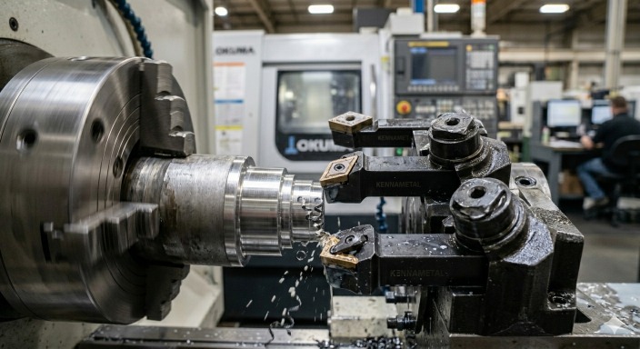
Turning Operations Used in Shaft Machining
A complete shaft turning operation rarely uses only step turning. It uses step turning as the primary diameter-generating operation alongside facing, grooving, threading, and sometimes drilling and boring, all combined in a single setup or coordinated across multiple setups to complete the shaft.
Facing cuts the shaft end perpendicular to the axis, establishing the length datum and a clean reference face. Step turning then produces all the diameter sections and shoulder features. Grooving cuts undercuts, snap ring grooves, oil grooves, and relief features at specific axial positions. Threading produces external or internal threads on shaft ends or flanges. Each operation contributes features that step turning alone can't produce.
Where Step Turning Fits Among Lathe Operations
Step turning is the backbone of shaft production, it defines the primary geometry. The other turning operations add functional features to the geometry that step turning created. On a CNC lathe with live tooling, milling operations for keyways, cross-holes, and flats extend the shaft's functionality further without a setup change.
A typical CNC step turning program for a gearbox input shaft runs approximately as follows. Face both ends to establish total length. Center drill both ends for between-centers support. Rough turn all diameters in sequence with a single rough turning tool. Finish turn all critical diameters. Cut snap ring grooves at the shoulder transitions where circlips locate components. Thread the shaft end for the nut that retains the bearing. Chamfer all diameter transitions to remove sharp edges. All of this happens in two or three setups, one from each end, on a CNC turning center with a turret that holds ten or more tools simultaneously.
The step turning operations produce the major diameters.
Shaft Turning and Stepped Shaft Machining Applications
Motor and Drive Shafts
Motor shafts are textbook step turning applications. A typical AC motor shaft has a bearing seat at each end (different diameters for drive end and non-drive end bearings), a shaft extension for the driven load, a seal journal, and a winding retention feature, each requiring its own diameter, tolerance, and surface finish. The step turning process produces all of these in a single setup, maintaining concentricity across all features that's impossible to achieve if the shaft is removed and rechucked between operations.
Drive shafts in gearboxes, conveyor systems, and power transmission equipment follow the same pattern, multiple functional shaft diameter, gear seats, coupling interfaces, and seal journals, all concentric and located to the tolerances the bearing and gear manufacturers specify.
Bearings, Gears, and Coupling Components
Bearing seats produced by step turning are held to specific tolerance and surface finish requirements from the bearing manufacturer. A standard deep groove ball bearing requires the shaft seat to be within k5 or m5 tolerance, typically ±0.006-0.013mm on a 40mm shaft, with Ra 0.8 µm or better and roundness within 0.005-0.008mm. These requirements are achievable by CNC step turning with finish turning parameters, sometimes followed by cylindrical grinding on the most critical journals.
Gear seats on stepped shafts need the correct interference or clearance fit for the gear hub, plus a shoulder to provide axial location, plus a keyway for torque transmission. The step turning operation produces the diameter and shoulder; the keyway is milled in a subsequent operation on the same setup if the lathe has live tooling.
Aerospace and Automotive Shaft Parts
Aerospace shafts, turbine shaft extensions, gearbox shafts, actuator shafts, carry the tightest tolerances in step turning manufacturing. Aerospace shafts often require extremely tight tolerances, low runout, and fine surface finishes, which are commonly achieved through a combination of CNC turning, in-process gauging, and cylindrical grinding.
Automotive stepped shaft machining, crankshafts, camshafts, transmission input shafts, differential pinion shafts, is high-volume production where the step turning process is optimized for cycle time alongside accuracy. Automated loading, in-process gauging, and tool life management systems run these shafts at volumes that manual step turning operations can't approach.
Materials Used in CNC Step Turning
| Material | Machinability | Typical Application | Key Consideration |
|---|---|---|---|
| 1045 Carbon Steel | Good | General shafts, motor shafts | Normalized or annealed for best machinability |
| 4140 Alloy Steel | Moderate | High-strength shafts, gearbox shafts | Often machined pre-heat treatment, finish after |
| 4340 Alloy Steel | Moderate-Difficult | Aerospace shafts, high-load applications | Requires sharp tooling, controlled cutting parameters |
| 17-4 PH Stainless | Difficult | Corrosion-resistant precision shafts | Work hardens, consistent feeds essential |
| 303 Stainless Steel | Good | General corrosion-resistant shafts | Free machining grade, best stainless for turning |
| 316L Stainless | Moderate | Marine, chemical, medical shafts | Work hardening tendency, sharp tools required |
| 6061-T6 Aluminum | Excellent | Lightweight shafts, aerospace applications | High speeds, sharp uncoated or DLC inserts |
| 7075-T6 Aluminum | Excellent | High-strength lightweight shafts | Better strength than 6061, similar machinability |
| Titanium Grade 5 | Difficult | Aerospace, medical shafts | Low thermal conductivity, heat builds at tool |
| Brass (C360) | Excellent | Bearing shafts, instrumentation | Free cutting, very high surface speeds possible |
| POM (Delrin) | Excellent | Light-duty plastic shafts | Sharp tools, low cutting speeds, no coolant needed |
| PEEK | Moderate | High-temp engineering plastic shafts | Abrasive, faster tool wear than standard plastics |
Advantages and Limitations of Step Turning
High Precision and Repeatability
CNC step turning produces diameter tolerances of ±0.010-0.025mm routinely on production runs without special measures. With in-process gauging and tool offset correction, ±0.005-0.010mm on critical sections is achievable as a production capability rather than a one-off achievement. The CNC program runs identically on every part, the same tool paths, same programmed coordinates, same cutting parameters. Part 500 is the same as part 1, which is what production shaft manufacturing requires.
The repeatability of CNC step turning is what makes it suitable for bearing fits, gear seats, and other interference fits where dimensional scatter across a production batch produces assembly problems. A batch of shafts where every bearing seat is within ±0.006mm of the target diameter assembles consistently. A batch with ±0.050mm scatter requires selective fitting, measuring each shaft and pairing it with a correspondingly measured bearing, which adds cost and defeats the purpose of production tolerancing.
Efficient Shaft Manufacturing
Step turning produces all diameters of a stepped shaft in one setup. The alternative, turning each section separately and joining them, introduces additional concentricity errors at each joint and adds assembly operations that CNC step turning eliminates. Single-setup step turning is faster, more accurate, and more reliable than any multi-piece alternative for the same shaft geometry.
On a CNC turning center with a turret holding rough, finish, grooving, and threading tools simultaneously, a complete stepped shaft from raw bar stock to finished part takes one setup and one cycle. For production volumes, this translates directly into cost per shaft that manual or multi-setup processes can't match.
Machining Challenges and Tool Wear
Long stepped shafts deflect under cutting forces, particularly at positions far from the chuck and tailstock support. This deflection produces diameter error, the shaft pushes away from the tool slightly, and the actual cut diameter is larger than the commanded diameter. Compensating with in-process measurement and tool offset correction manages this, but it adds measurement time and requires the CNC programmer to anticipate where deflection will be worst and adjust parameters accordingly.
Tool wear in step turning affects dimensional accuracy progressively. As the insert wears, the effective cutting diameter changes, a worn insert cuts slightly larger on external turning because the worn edge doesn't reach as far into the workpiece. Tool life management, changing inserts at defined intervals based on parts count or cutting time, not just visual wear inspection, maintains dimensional consistency across a production run. On precision shaft turning where bearing seats are held to ±0.008mm, tool wear of 0.005mm per insert index is significant and needs to be managed rather than ignored.
Step Turning vs Other CNC Turning Operations
| Factor | Step Turning | Straight Turning | Taper Turning | Profile Turning |
|---|---|---|---|---|
| Geometry produced | Multiple diameters with flat shoulders | Single uniform diameter | Conical taper | Complex curved profile |
| Axis movement | Z-axis with X repositioning at each step | Z-axis only | Simultaneous X and Z | Coordinated X and Z per profile |
| Number of diameters | Multiple (2 or more) | One | One (varying) | Variable |
| Shoulder features | Yes, at each diameter transition | No | No | Depends on profile |
| Primary application | Shafts with bearing/gear seats | Simple cylinders, pins | Morse taper shanks, conical seats | Contoured profiles, complex geometry |
| Programming complexity | Moderate | Simple | Simple to moderate | High |
| Setup requirements | Workholding for full shaft length | Shorter setup acceptable | Compound slide or CNC interpolation | CNC required |
| Typical tolerance | ±0.010-0.025mm per diameter | ±0.010-0.025mm | ±0.015 - 0.030 mm (on diameter), ±5' (on angle) | ±0.025-0.040mm |
| Tool changes required | Multiple (rough, finish, shoulder) | One or two | One or two | Multiple profile tools |
| Where it's used | Motor shafts, gearbox shafts | Pins, bushings, simple rods | Tooling shanks, valve seats | Cams, complex mechanical components |
How to Optimize CNC Step Turning for Precision Parts
Toolpath Optimization
The step turning toolpath sequence affects both cycle time and dimensional accuracy. Roughing all diameters before finishing any diameter is more efficient than rough-and-finish each section sequentially, it keeps the rough tool in the turret for the entire roughing phase, reduces tool changes, and maintains thermal stability in the workpiece before the finish pass.
For the finish pass sequence, working from the free end toward the chuck reduces deflection effects. As finish passes are completed toward the chuck, the remaining unturned material provides support, the supported cross-section is larger than the already-turned section would be. This is particularly important on slender shafts where deflection is the primary accuracy challenge.
Constant surface speed (CSS) mode, where the spindle speed automatically adjusts as the diameter changes to maintain constant cutting speed, is worth using in CNC step turning on shafts with significant diameter variation. A shaft with sections at 80mm and 20mm diameter needs spindle speed 4x higher on the small diameter to maintain the same surface speed as the large diameter. CSS does this automatically, maintaining consistent chip formation and surface finish across all sections without manual speed adjustments in the program.
Reducing Vibration and Chatter
Chatter in step turning shows up as a distinctive pattern on the machined surface, regular wave marks that look like a fine corduroy texture running around the circumference. Chatter is usually caused by insufficient rigidity, unstable cutting conditions, or unsupported shaft sections.
For persistent chatter on slender shafts, the setup needs to change. Adding steady rest support at the chatter location stiffens the workpiece against the deflection that drives vibration. Reducing tool overhang stiffens the tool side of the equation. Using a smaller lead angle insert, 45° lead angle rather than 75°, shifts more of the cutting force in the axial direction rather than radially, reducing the force component that drives workpiece deflection and chatter.
Maintaining Tight Tolerances
Tight tolerances on stepped shaft machining require more than good programming, they require process control throughout the turning operation. Thermal stability is the first consideration. The spindle, tooling, and workpiece all expand as they warm up, and a CNC turning center that's been running for an hour is at a different thermal state from one that just started. Running warm-up cycles before precision shaft turning, or using in-process gauging that corrects for thermal drift, maintains accuracy regardless of thermal state.
Tool offset management is the second consideration. Every tool in the turret has a measured offset that the CNC controller uses to compensate for tool position, as tools wear, those offsets need updating. For bearing journal tolerances of ±0.008mm, a tool offset error of 0.010mm is already out of tolerance. Measuring the first part at each diameter after finish turning and updating the tool offset before continuing is the correct practice for this level of precision, not measuring at the end of the batch and finding that parts 2-50 were all 0.015mm over.
Coolant management affects dimensional accuracy more than most operators realize. Flood coolant keeps the workpiece and tool at a consistent temperature during the cut. Parts measured immediately after turning are warm and measure slightly larger than when cooled to room temperature. Either measure warm consistently and know the thermal correction factor, or let parts stabilize to room temperature before inspection. Inconsistent measurement temperature produces apparent dimensional variation that is actually thermal expansion, not machining variation.
FAQ About Step Turning
Q: Is step turning used for stepped shafts only?
No, step turning is also used for shoulders, bearing seats, threaded transitions, and multi-diameter cylindrical parts.
Q: How are shoulders measured after step turning?
Shoulders are typically measured using calipers, micrometers, depth gauges, or CMM inspection depending on tolerance requirements.
Q: Can CNC lathes machine multiple shaft diameters in one setup?
Yes, CNC step turning allows multiple shaft diameters and shoulder features to be machined in a single setup.
Q: What causes chatter during shaft turning?
Chatter during shaft turning is usually caused by poor rigidity, excessive tool overhang, incorrect feeds and speeds, or unsupported long shafts.
Q: What is the difference between step turning and grooving?
Step turning creates diameter transitions along a shaft, while grooving cuts narrow recessed channels into the surface.
Keep Learning
Laser Engraving Aluminum: Marking Methods & Surface Effects
Key Takeaways Laser engraving usually removes base material to create a recess. Laser marking is a broader term that can describe a surface-color change or material removal, so the process name alone does not define the final result. On aluminum, alloy and surface finish affect marking contrast. A light mark on dark anodized aluminum is a common design target, but the actual appearance depends on the finish and laser process. JLCCNC laser marking produces a recessed area 0.03–0.1 mm deep. The result i......
CNC Cutting Fluid: Types, Functions, Applications, and Selection Guide
Key Takeaways Cutting fluid in machining performs four functions simultaneously: cooling the tool and workpiece, lubricating the tool-chip interface to reduce friction, carrying chips away from the cut zone, and protecting machined surfaces from corrosion between operations. Different machining operations need different fluid priorities: high-speed aluminum milling may need adhesion control and chip evacuation, threading and tapping need strong lubrication, and grinding requires both cooling and fine ......
Blind Hole Machining Guide: What Is a Blind Hole, Types of Holes, and Tapping Tips
What Is a Blind Hole? Types of Holes and CNC Hole Machining Explained In CNC machining, few operations challenge process control and tool stability as much as blind hole machining. A blind hole is a hole that terminates at a defined internal depth rather than breaking through the opposite surface. Because the cavity is enclosed at the bottom, chip evacuation, thermal behavior, tool wear, and dimensional accuracy become far more difficult to manage compared to through-hole machining. These constraints ......
Rake Angle in Machining: Machinists’ Guide to Perfect Cuts
What is Rake Angle? (minaprem) If you've ever stood in front of a CNC machine or a manual lathe, you know that the cutting tool's geometry isn't just some arbitrary design. Every angle, edge, and surface has a job to do, and one of the most important of those is the rake angle. We've been running machines long enough to know that rake angle can make or break your surface finish, tool life, and machining efficiency. In this guide, we're going to walk you through what rake angle is, how it works, and ho......
Sheet Metal vs CNC Machining: A Guide to Choosing the Right Method for Your Metal Parts
Quick Answer: Choose sheet metal for uniform-thickness enclosures, panels, and formed brackets when bends and production volume support lower unit cost. Choose CNC machining for variable wall thickness, precision bores, tight feature relationships, and complex 3D geometry. Use a hybrid design when a formed structure needs precision-machined interfaces. A quote comes back for a bracket, and it's priced as a CNC part — machined from solid aluminum, a few hours of spindle time, a per-part cost that makes......
What Steps Are Taken To Minimize Waste In CNC Machining Processes?
How to Reduce Waste in CNC Machining: 5 Practical Strategies Quick Answer: CNC machining waste is reduced mainly through DFM, near-net stock, efficient toolpaths, preventive tool maintenance, and alloy-segregated recycling. The biggest gains usually come before cutting: reduce unnecessary material removal and prevent scrap or rework. Every CNC-machined part starts as more material than it ends up being. A pocket gets milled out, a profile gets cut away, a boss gets faced down to size — and all of that......