What Is a Chamfer? A Practical Guide for CNC Machining and Design
11 min
- What Is a Chamfer Edge in CNC Machining
- Common Chamfer Angles and Design Rules
- Chamfer Machining in CNC Manufacturing
- How to Specify a Chamfer on a Drawing
- Practical Chamfer Design Tips for CNC Parts
- CNC Chamfer Machining Services at JLCCNC
- Conclusion
- FAQ
In CNC machining and mechanical design, small edge details can have a significant impact on part quality, safety, and manufacturability. A chamfer is one such feature. While it may appear simple, chamfer design directly affects how a part is machined, assembled, and used.
Chamfers are widely applied to remove sharp edges, ease assembly, and improve overall part reliability. Engineers use chamfers to improve tool access, accommodate minor misalignment during assembly, and extend part service life.
Chamfer - A Practical Guide for CNC Machining [Product source: AI-generated]
This guide explains what a chamfer is, how it is used in CNC machining, common chamfer angles, and how to specify chamfers correctly on engineering drawings to ensure manufacturable part designs. Whether you are a mechanical engineer, product designer, or sourcing CNC machining services, understanding chamfer design can help reduce cost, avoid design issues, and improve part quality.
What Is a Chamfer Edge in CNC Machining
A chamfer is a flat, angled cut made on an edge or hole to replace a sharp corner, improving safety, assembly guidance, and manufacturability in CNC machining.
Chamfer Basic Geometry [Image Source: Shutterstock.com]
Chamfers are used in CNC machining for a variety of functions:
● Safety: Breaks sharp edges to reduce cuts, handling damage, and shipping risks.
● Assembly: Adds a lead-in that helps mating parts align and start smoothly.
● Burr control: Removes burrs and cleans edges around holes, pockets, and slots.
● Tool access: Gives cutting tools a cleaner approach and exit near edges.
● Cost: Reduces deburring, rework, and inspection effort when specified consistently.
Chamfers can be applied to:
● External edges
● Internal holes
● Slots
● Pockets
● Counterbores
● Thread starts
Common Chamfer Angles and Design Rules
CNC machining mostly utilizes a 45-degree chamfer angle. The reason why this angle is popular is:
● Regular chamfer tools are easily accessible.
● It is easy to program.
● It offers symmetrical edge relief.
Standard Chamfer Angles Used in CNC Machining
Chamfers are not to be restricted to 45 degrees. Typical chamfer angles are:
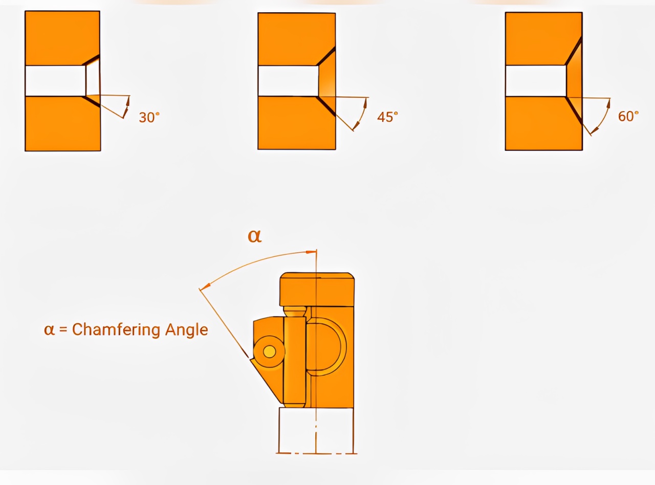
Common Chamfer Angles and Design Rules [Image Source: Shutterstock.com edited by AI]
| Chamfer Angle | Typical Use |
| 45° | General edge break, deburring, and assembly guidance |
| 30° | Thread lead-ins, shallow entry chamfers |
| 60° | Countersinks, fastener seating |
| 90° | Rare, used for specific mating requirements |
| Custom angles | Functional or aesthetic design needs |
In CNC chamfer machining, the angle of choice may be determined by:
● Tool availability
● Part function
● Mating component geometry
● Industry standards
How to Choose the Right Chamfer Size
The correct chamfer size is as important to pick as the angle. Chamfers that are oversized can cause weakening, and those that are undersized are ineffective in removing edges or helping in assembly. Here are practical rules of thumb for selecting chamfer size:
1. Take the Minimal Chamfer That Satisfies the Use Case
Chamfers need not be bigger than is necessary to be effective in undertaking the action required. Simple deburring or edge safety chamfers can be applied with chamfers in the range 0.2-0.5 mm. The chamfer over-sizing is unnecessary since it will not be considered of any extra value.
2. Match Chamfer Size to Part Scale
The size of the chamfer must relate to the size and the thickness of the part. With bigger parts, larger chamfer sizes can be used without strength loss, and small or precision parts need minimum side bends. Using appropriate dimensions helps ensure dimensional accuracy and part integrity.
3. Consider Mating Parts
The tolerances of mating features must be considered in determining the size of chamfers in the case of direct assembly. The chamfer must also be at least as big or even bigger than the anticipated misalignment so that it can be inserted easily. This enhances the reliability of the assembly process and minimizes the chance of interference.
4. Avoid Unnecessarily Tight Tolerances
Chamfer hardly needs tight dimensional tolerances except where it has a direct bearing on part functionality or fit. Excessive chamfer tolerancing results in longer CNC machining time and inspection costs. High tolerances will enhance manufacturability and lower the cost of production.
| Application | Typical Tolerance | Cost Impact |
| Edge break / deburring | ±0.2–0.5 mm | Lowest cost |
| Non-critical chamfers | ±0.1–0.3 mm | Low cost |
| Assembly guide chamfers | ±0.05–0.1 mm | Moderate cost |
| Functional / precision chamfers | ±0.02 mm or tighter | High cost |
| Cosmetic chamfers | ±0.1 mm | Controlled cost |
5. Equalize the Chamfers on the Part
Having equal chamfer size and angle on a part makes CNC programming and tooling easier. Standardization saves on tool changes, set-up time, and causes of machining errors. This is most useful when dealing with high volume or repeat production.
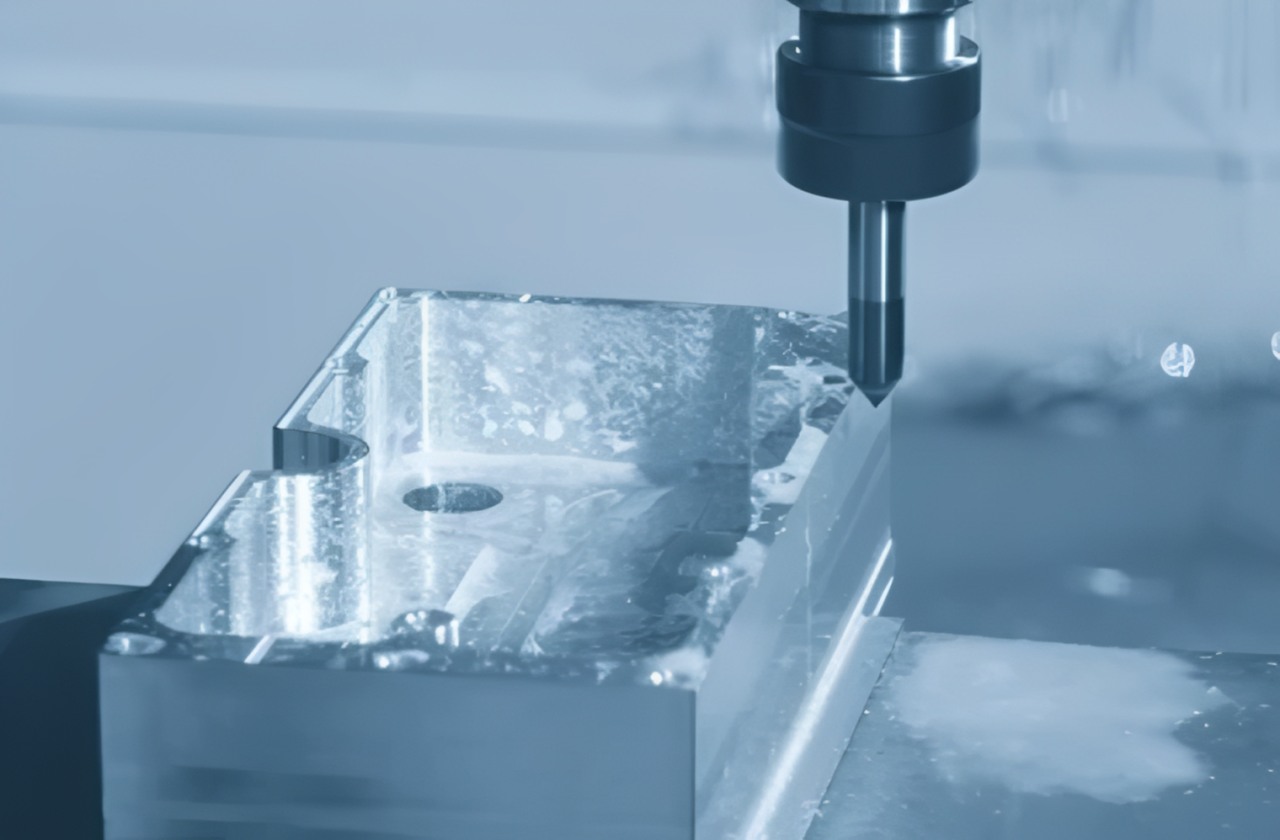
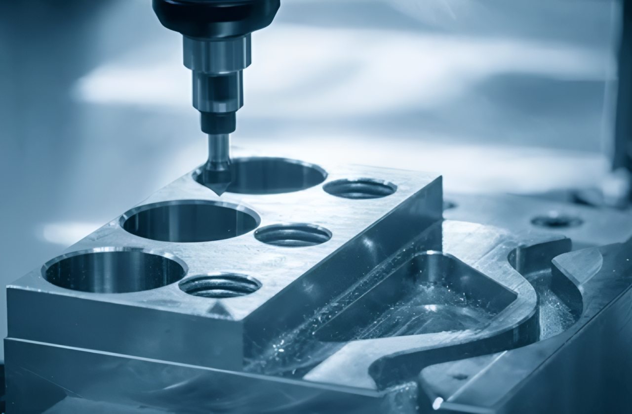
Chamfer Machining in CNC Manufacturing
Chamfer CNC Machining [Image source: Shutterstock.com]
How CNC Machines Cut Chamfered Edges
How chamfers are typically machined on CNC equipment:
In the machines involving CNC machining, the chamfers are often machined as a finishing operation after the basic geometry has been made. The CNC machine adheres to a programmed toolpath, which cuts the material along the edge at the desired angle.
Chamfer cutting may be carried out with:
1. CNC milling machines
2. CNC lathes
3. Multi-axis CNC systems
In external edges, the cutting tool follows the edge profile with the depth and angle held constant. In the case of internal holes, the chamfer is cut by circular interpolation.
The precision of CNC chamfer machining relies upon:
● Tool geometry
● Machine rigidity
● Proper tool offset and calibration
● Surface finish needs
Tools and Methods for CNC Chamfering
Chamfering: various tools find application in CNC chamfer machining:
1. Chamfer Mills
Chamfer mills are dedicated cutters designed to produce clean, consistent chamfers. They’re typically the most reliable option when you need repeatable edge quality on both external edges and accessible internal features. They are very precise, have predictable and high edge quality, and are most frequently utilized to cut a clean and accurate CNC chamfer. The tools are best suited to external sides as well as internal features whenever possible.
2. End Mills (Angled Path)
Chamfer may be machined using standard end mills programmed to cut an angled toolpath. Although the tooling is not required in this method, this is typically less productive and possibly less predictable. It is mostly applied with simple or low-volume machining.
3. Countersink Tools
The countersink tools are mainly used in chamfering holes and primarily in cases where a fastener, such as a flat-head screw, must lie flat. They yield stable chamfer angles that comply with standard fastener specifications. This process is typical of CNC parts that revolve around assembly.
4. Multi-purpose deburring tools
Multi-function deburring tools are used to provide rapid break-edge breaks in high production volume work-places. They are not necessarily as precise as dedicated chamfer mills when it comes to dimensional accuracy, but can perform well in removing burrs. They are commonly employed when speed is valued, but tight tolerances are not so important.
5. Manufacturing Considerations
The wear of tools should be stringently observed during the chamfer machining process, especially with hard materials like stainless steel or titanium. The choice of tools and chamfering strategy is all dependent on burr formation on ductile metals, internal features accessibility, and optimization of cycle time. Professional CNC machining services strike a balance between these in order to obtain a uniform quality at the most reasonable cost.
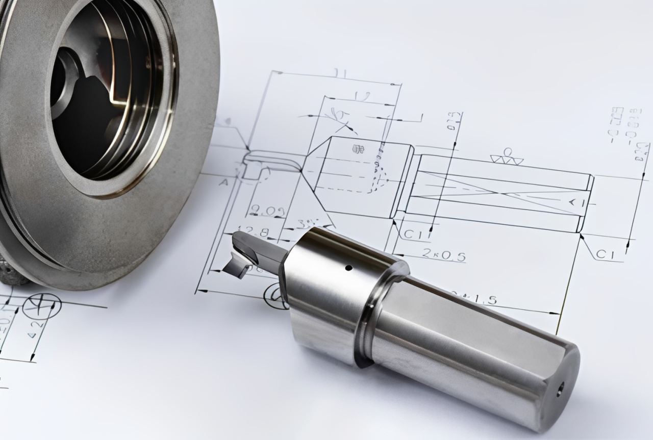
How to Specify a Chamfer on a Drawing
Here are some ways to specify a chamfer on Drawing;
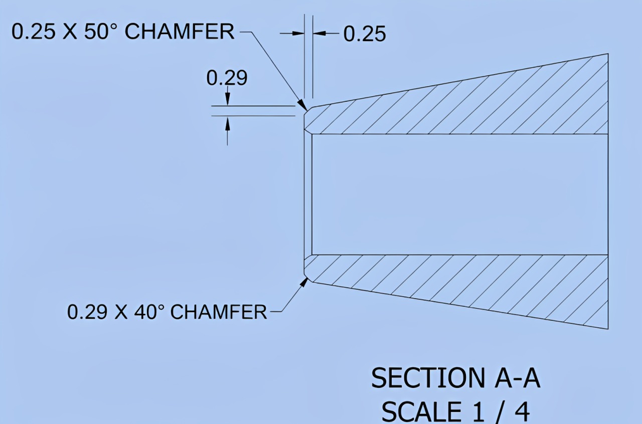
Chamfer Drawing [Image source: Shutterstock.com]
Chamfer Callout on Engineering Drawings
Engineering drawings are required to be correctly specified for chamfering. Unclear chamfer callout may result in rework, rejection, or misinterpretation.
A typical chamfer callout consists of:
● Chamfer size
● Chamfer angle
Example:
C0.5 x 45°
or
0.5 x 45°
This represents a chamfer whose linear dimension of 0.5 mm is at a 45-degree angle.
When the angle is not specified, 45° is commonly assumed in practice if no angle is specified, but drawings should always state the angle to avoid ambiguity.
Common Chamfer Symbols and Notation Examples
Chamfers are normally denoted by:
● Leader lines point to the edge
● Text callouts
● General notes (herein repeated chamfer)
Examples:
● ALL SHARP EDGES: C0.3
● 4X C1 x 45°
● CHAMFER AS SHOWN
Best practices include:
● There is a clear identification of the number of chamfers.
● Avoiding crowded annotations
● Standard drafting conventions (ISO or ASME)
Clear chamfer callouts reduce back-and-forth, speed up CAM programming, and prevent scrap from misinterpretation.
Practical Chamfer Design Tips for CNC Parts
So, let’s discuss this in depth.
Practical Chamfer Design Tips for CNC Parts [shutterstock.com]
Design Considerations to Improve Machinability
These may include:
1. Keep Chamfers Consistent
One edge size and angle that is shared on several edges helps to minimize tool changes on a CNC machine and to complicate programming and operation. Stability enhances the efficiency in machining and reduces the total production time. It also reduces the chances of mistakes in the setup and implementation.
2. Do Not Use Unnecessary Custom Angles
Special tooling or time to set up special tooling is sometimes necessary to achieve custom chamfer angles. Common angles, like 45 degrees, are simpler to machine and less expensive. Common angles are used to minimize machining complexity and lead times.
3. Design for Tool Access
The chamfers must be made in a way that they can be accessed by common CNC chamfering tools. Inaccessibility might involve special tooling or multi-axis machining, which makes it more expensive. Manufacturability and consistency are enhanced by keeping the tools accessible.
4. When to Use Chamfers Instead of Fillets
Chamfers are typically faster to machine and less expensive to cut compared to fillets since it utilizes straight tool pathways. Fillets tend to undergo contouring processes, which raise cycle time. Chamfer is the more cost-effective treatment of the edge when it is practicable.
5. Limit Chamfering Only where necessary
Chamfering all edges is not always value-added and also adds more machining time. Here, Chamfer should be mentioned only in the case of functional, safety, or assembly value. This prevents over- engineering and CNC parts remain affordable.
Common Chamfer Design Mistakes to Avoid
● Over-tolerancing chamfers
● Failure to indicate chamfer angles
● Using fillets where chamfers would be more suitable
● Chamfer size smaller than the effective cutting edge of available tools
● Inconsistent application of the chamfer
By avoiding such errors, part yield will be enhanced, and the costs associated with CNC machining should decrease.

CNC Chamfer Machining Services at JLCCNC
JLCCNC provides CNC chamfer machining for acrylic, metal, and engineering plastic parts across prototyping and production runs. With dedicated CNC milling and turning capabilities, we help customers add consistent edge breaks and lead-ins for safer handling and easier assembly.
Our chamfer capabilities include:
● Minimum chamfer size: down to C0.2
● External and internal chamfers on edges, holes, pockets, and slots
● Common angles such as 45°, 30°
● Chamfer milling and deburring for repeatable edge finishing
● Prototype to batch production with consistent inspection standards
Conclusion
Chamfers are very tiny yet vital aspects used in CNC machining and have a great impact on the safety of the part, assembly efficiency, and part life. Chamfers that are well formulated lessen sharp edges, aspects of tool accessibility, stress concentration, and general manufacturability. Engineers can prevent some of the design errors that are experienced by choosing the standard chamfer angles, the right sizes and tolerances, as well as clearly defining chamfers on engineering drawings, helping to reduce production costs.
In combination with professionally-performed CNC chamfer machining services, chamfer design guarantees the same quality and dependable operation in both prototype and production parts.
FAQ
What is the chamfer of CNC machining?
A chamfer is an angled cut on the edge that substitutes a sharp end to enhance safety, assembly, and durability.
Is a chamfer the same as a bevel?
Not exactly. A chamfer is usually a small, specified edge cut (often C × 45°) to break a sharp corner or add a lead-in. Bevel is a broader term for any angled edge and often implies a larger angled cut.
When should I use a chamfer instead of a fillet?
Use a chamfer for easy assembly lead-ins, edge breaking, and lower machining cost. Use a fillet when you need better stress reduction on load- or fatigue-critical corners.
What is the typical chamfer angle?
The most frequently used chamfer angle in CNC machining is 45 degrees.
What is the difference between chamfer and fillet?
A chamfer is a flat, angled edge, while a fillet is a rounded transition between two surfaces.
Is chamfer cost-effective?
Well-designed chamfers can save money by making tools easier to access and decreasing the number of burrs.
How do you give chamfer on a drawing?
By specifying the chamfer size and angle with a standard callout like 0.5 x 45°.
Popular Articles
• Cutting with Precision: A Comprehensive Guide to CNC Water Jet Technology
• CNC Coolant Explained: Types, Maintenance & Safety
• Rake Angle in Machining: Machinists’ Guide to Perfect Cuts
• What Steps Are Taken To Minimize Waste In CNC Machining Processes?
• How EDM Wire Cutting Works: Complete Guide to Precision CNC Wire Cutting
Keep Learning
Chip Thinning in CNC Machining: Formula, Feed Rate & Calculator
Key Takeaways Chip thinning lowers actual chip thickness at narrow radial engagement. Feed per tooth must rise to maintain the intended cutting load. The formula connects cutter diameter, stepover, and engagement geometry. A calculator applies the correction before feed-rate programming. The method suits partial-width cuts rather than full-width slotting. Chip thinning takes place when a cutter takes a narrow stepover in order to make each chip thinner than the programmed chip load suggests. Understan......
Chatter in Machining: Causes, Effects, and How to Reduce It
CNC milling operation producing visible chatter marks on an aluminum workpiece Quick Chatter Diagnosis Checklist Symptom Most Likely Cause First Action High-pitched squeal Regenerative chatter Change spindle speed ±15% Chatter only in deep pockets Excessive tool overhang Shorten tool Chatter on thin walls Low workpiece rigidity Improve fixturing Chatter after tool replacement Runout / holder issue Check tool holder Chatter only during finishing DOC too small / rubbing Increase feed or adjust speed It ......
What Is Tool Offset in CNC? Types, Setup & Best Practices
CNC tool offset setup with measurement overlay Key Takeaways CNC offsets connect programmed intent with actual cutter position. Length data guides Z-axis depth control. Radius data protects part size during contour milling. Geometry values define the cutter's measured baseline. Wear values support fine correction during production. Verified data lowers scrap risk before full machining. Good offset habits protect tools, fixtures, and parts. In the context of CNC machining , tool offset is the quiet set......
Trochoidal Milling: Complete Guide to High-Efficiency CNC Machining
Key Takeaways Trochoidal milling combines circular cutter motion with continuous forward feed. The cutter normally engages 5 to 20% of its diameter instead of making a full-width cut. A smaller engagement angle limits force changes during slotting and pocket roughing. Low radial engagement often allows greater axial depths of cut than conventional slot milling. CAM software calculates the circular path automatically from the selected machining parameters. This strategy is widely applied to titanium, s......
What Is Die Casting? Process, Materials, and Applications
Key Takeaways Die casting is a metal casting process that forces molten metal into a reusable steel mold under high pressure, producing parts with tight tolerances and good surface finish at high volume. Aluminum die casting is the most common form by far, thanks to its combination of light weight, decent strength, and good corrosion resistance. The die casting process runs through mold preparation, injection, cooling, and ejection in a cycle that can repeat every few seconds to minutes depending on p......
First Angle vs Third Angle: Understanding Orthographic Projection Methods
Key Takeaways Orthographic projection is the system that lets a 3D part be represented through multiple 2D views, front, top, side, and so on. First angle projection and third angle projection are the two standard methods for arranging those views, and they place views in opposite positions relative to the object. First angle projection is the ISO standard used across most of Europe, India, China, Russia, and many other countries following ISO standards Third angle projection is the standard in the Un......