Pocket Milling in CNC Machining: Definition, Toolpaths, and Best Practices
14 min
- What Is Pocket Milling?
- Types of Pocket Milling Operations
- Toolpaths and Strategies for Pocket Milling
- Choosing Tools & Parameters for Pocket Milling
- Advanced Pocket Milling Techniques
- Common Challenges in Pocket Milling & How to Overcome Them
- FAQ
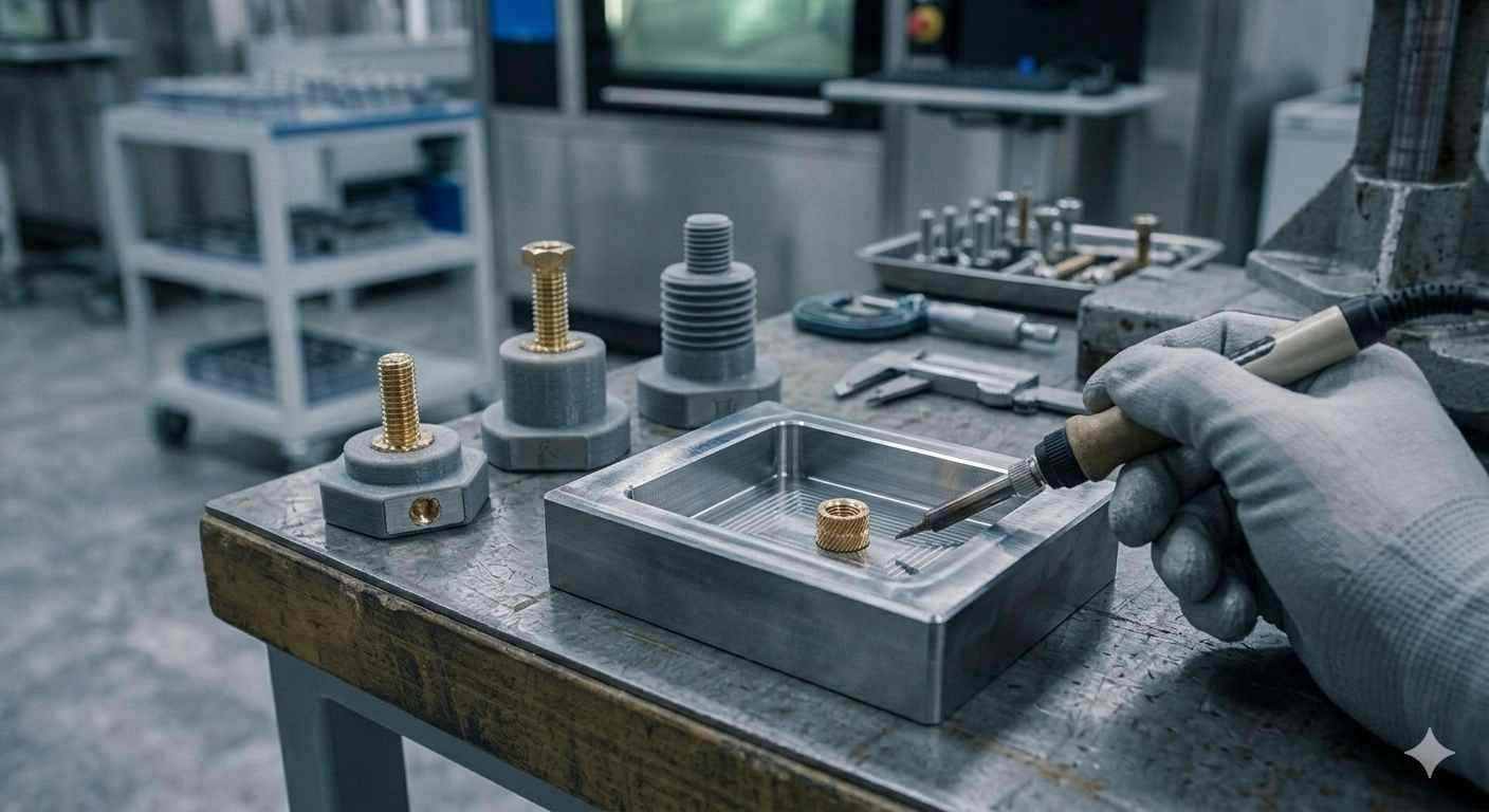
(AI generated) CNC machined metal part with a precision pocket cavity on a workshop workbench.
In most machine shops, similar pocket features appear across many different parts. Flat stock goes into the mill, and a few minutes later, there’s a clean, precise cavity cut into it. That cavity might hold electronics, reduce weight, house a bearing, or simply remove unnecessary material.
That process is pocket milling, and despite looking simple on the surface, it’s one of the operations where strategy, toolpath choice, and machining discipline really start to matter. Pocket CNC operations are widely used in CNC milling to create recessed cavities and internal features.
Poor pocket strategies waste hours of machine time, break tools, and leave ugly floors that need rework. A well-planned pocket, on the other hand, removes material efficiently while keeping tool wear low and dimensional accuracy high.
In this guide, we’ll break down what pocket milling actually is, when it’s used, and how machinists approach it to keep parts accurate and production-friendly.
What Is Pocket Milling?
Pocket milling is a CNC machining operation that removes material from inside a defined boundary to create recessed cavities within a part. Instead of cutting along an external edge or profile, the cutting tool moves inside the material to clear out an internal area.
You’ll see pocket milling used everywhere, from lightweight aerospace components to electronic housings and mold cavities.
Key characteristics of CNC pocketing:
● Creates internal cavities or recessed areas inside a part rather than cutting external edges
● Uses controlled toolpaths to remove material gradually while maintaining dimensional accuracy
● Can include flat-bottom pockets, stepped pockets, or contoured pockets, depending on the design
● Often requires roughing and finishing passes to balance speed and surface quality
● Works across many common machining materials, including:
○ Aluminum alloys
○ Stainless steel
○ Carbon steel
○ Brass and copper
○ Engineering plastics such as nylon or POM
In other words, whenever a part design includes a recessed region with defined walls and a floor, pocket milling is usually the machining strategy that makes it happen.
Types of Pocket Milling Operations
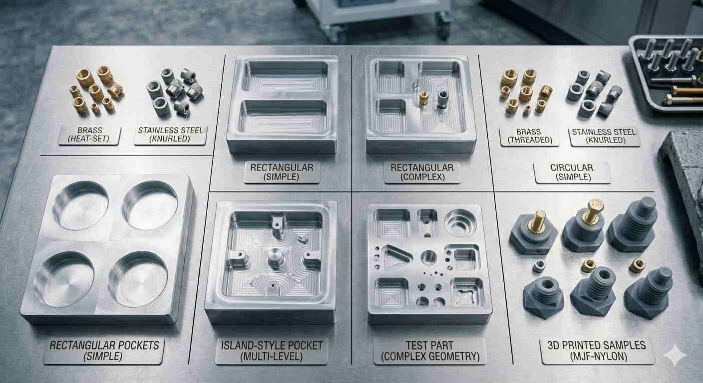
(AI generated) Various CNC pocket samples showing rectangular, circular, and island-style geometries on a workbench.
Pocket milling operations are usually classified by how the pocket boundary is defined relative to the workpiece.
This boundary determines how the CAM software generates toolpaths and how the cutter enters the material.
In practice, most CNC pockets fall into three structural categories: closed pockets, open pockets, and pockets with islands.
Closed Pockets
A closed pocket is surrounded by material on all sides. The pocket boundary lies entirely inside the part geometry.
This is the most common pocket type in CNC milling. Typical examples include recessed housings, mounting cavities, and electronic enclosures.
Characteristics:
● All pocket walls are internal to the part
● The cutter must enter through ramping, helical interpolation, or pre-drilled entry
● Chip evacuation can become difficult in deeper cavities
● Roughing and finishing passes are normally required
Closed pockets are frequently used in:
● electronic housings
● fixture plates
● mold cavities
● lightweight structural components
Because the boundary is fully enclosed, CAM systems treat it as an enclosed machining region and generate clearing toolpaths inside the pocket.
Open Pockets
An open pocket has at least one side that intersects the outer edge of the workpiece.
Instead of being fully enclosed, the cavity is partially open to the outside of the part. In many designs, this looks more like a recessed step or shelf than a traditional cavity.
Common examples include:
● weight-reduction cutouts
● side access channels
● open slots or stepped features
Open pockets behave differently during machining:
● chips evacuate more easily because the cavity is open
● the tool can often enter from the side instead of ramping vertically
● cutting engagement may change suddenly near the open boundary
For this reason, CAM software often generates toolpaths that start outside the part and move inward, reducing tool load during entry.
Pockets With Islands
A pocket with an island contains internal geometry that must remain unmachined.
The island is essentially a raised feature inside the cavity. During pocket milling, the cutter must remove surrounding material while preserving this internal region.
Typical island features include:
● bosses for mounting screws
● alignment posts
● structural ribs inside housings
Machining pockets with islands requires more complex toolpath planning because the cutter must:
● clear material around multiple boundaries
● avoid collision with the island geometry
● maintain consistent tool engagement
Modern CAM systems automatically detect enclosed regions and treat them as islands, generating toolpaths that move around these internal features while clearing the surrounding material.
In complex parts, a single pocket may contain multiple islands, or islands may even contain smaller internal pockets.
Simple Shape Variations
Within these structural categories, pockets can take many geometric shapes, including:
● rectangular pockets
● circular pockets
● irregular or freeform cavities
Regular shapes, such as rectangles or circles, are easier to program manually, while irregular pockets typically rely on CAM-generated toolpaths.
In modern CNC workflows, the pocket structure (open, closed, island) has a larger impact on machining strategy than the exact shape of the cavity.
Toolpaths and Strategies for Pocket Milling
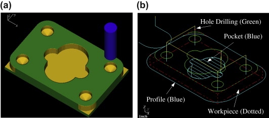
CNC pocket milling example showing a machined pocket and toolpath on a plate workpiece. (Source: ScienceDirect)
The pocket shape is only half the story. The toolpath strategy determines how efficiently the cutter removes material and how much stress is placed on the tool.
Two programs cutting the exact same pocket can have dramatically different cycle times depending on how the CAM software generates the path. Some strategies prioritize speed, others prioritize tool life or surface finish.
Good pocket CNC milling usually combines multiple strategies rather than relying on a single pass.
Roughing vs. Finishing Paths
CNC pocketing almost always happens in two stages: roughing and finishing.
Roughing is where most of the material is removed. The goal isn’t perfect accuracy. It’s simply clearing the bulk of the material quickly while leaving a small allowance for finishing.
During roughing, programmers typically leave 0.2–0.5 mm of stock on pocket walls and floors. This leftover material ensures the finishing pass cuts cleanly rather than rubbing against the surface.
Finishing comes afterward. The cutter removes that remaining stock in a lighter pass, producing the final surface quality and dimensional accuracy.
Without a proper finishing pass, pocket walls often show visible tool marks and inconsistent dimensions.
Common Toolpath Methods
Modern CAM systems offer several different CNC pocketing strategies, each suited to different machining conditions.
Z-level pocketing removes material layer by layer from the top down. It’s simple and predictable but can create sudden tool engagement in corners.
Spiral pocketing moves the cutter gradually inward or outward in a continuous path. This reduces abrupt direction changes and often improves surface finish.
Trochoidal milling is another advanced pocketing strategy where the cutter follows circular looping paths to maintain consistent engagement and reduce tool load.
Adaptive clearing (also called dynamic milling) keeps the cutter engagement consistent throughout the cut. Instead of sharp direction changes, the tool moves along smooth, flowing paths that maintain steady cutting forces.
In many shops today, adaptive strategies are used for roughing, followed by a lighter contour pass to finish the pocket walls.
For engineers who need complex pocket machining with reliable tolerances, JLCCNC provides online CNC milling with 3-axis to 5-axis capability and fast production turnaround.
With their online CNC platform, you can:
● Upload your CAD file for an instant machining quote
● Choose from aluminum, steel, brass, or engineering plastics
● Produce complex pockets using 3-axis to full 5-axis CNC milling
● Get prototype parts delivered in as fast as a few days
● Achieve tolerances up to ±0.05 mm for qualified designs
● Support both rapid prototyping and small-batch production
If your design includes deep cavities, internal pockets, or multi-step pocket machining operations, their machining service can handle both prototypes and small-batch production with consistent tolerances.

Choosing Tools & Parameters for Pocket Milling
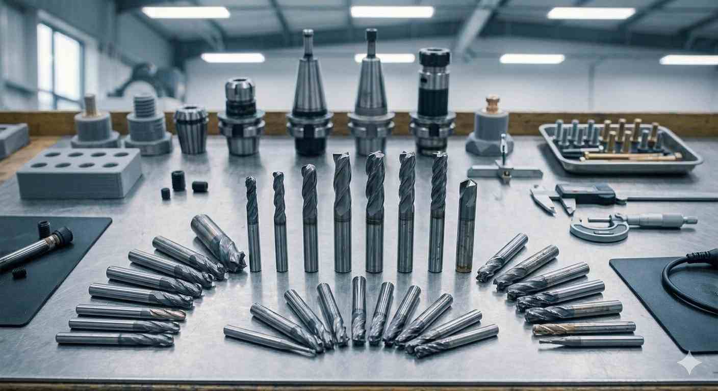
(AI generated) CNC end mills and machining tools arranged on a workshop workbench for tool selection.
Once the pocket CNC geometry is defined, the real performance difference comes down to tooling and cutting parameters. Two programmers can run the same pocket on the same machine and still get completely different cycle times depending on tool choice and how aggressively they push feeds and engagement.
CNC pocketing puts a constant side load on the cutter. If the tool, speed, and engagement aren’t balanced properly, you’ll see chatter marks, tool wear, or inconsistent pocket dimensions. Getting this right isn’t just about speed; it’s about stability.
Tool Selection for Pocket Milling
Most pockets are cut with flat end mills, but the exact tool geometry depends heavily on the material and pocket depth. If you need a broader framework for choosing the right end mills and cutters, this guide covers flute count, coatings, and selection rules that apply directly to pocketing.
For aluminum, machinists often use 2- or 3-flute carbide end mills. They evacuate chips well and allow higher feed rates without packing chips inside the pocket.
For steels and tougher alloys, 4-flute carbide tools aremore common because the extra flute increases rigidity and improves surface finish during finishing passes.
Deep pockets introduce another constraint: tool reach. As the stick-out increases, rigidity drops fast. A good rule many programmers follow is keeping the tool length-to-diameter ratio below 4:1 whenever possible. Beyond that, chatter becomes much harder to control.
Corner radii matter too. If the pocket has tight internal corners, the cutter diameter must match the smallest radius. The tool simply cannot reach the geometry.
Feeds & Speeds Optimization
Feed rate and cutting speed determine whether the cut runs smoothly or turns into a vibration problem.
For pocket machining, the goal is steady chip formation rather than aggressive material removal. If the feed is too low, the tool rubs instead of cutting, which accelerates wear. If it’s too high, the cutter overloads when engagement spikes near corners.
Most programmers start with manufacturer recommendations and then adjust based on:
● spindle power
● machine rigidity
● pocket depth
● material hardness
Aluminum pockets are often machined at higher spindle speeds compared with steel, especially when using small-diameter carbide end mills. Steel pockets, on the other hand, typically require slower spindle speeds but higher cutting forces.
Coolant also plays a role here. In deep pockets, chip evacuation often becomes the limiting factor rather than spindle power.
Balancing Step-Down & Step-Over
Pocket machining efficiency is largely determined by two numbers: step-down (axial depth of cut) and step-over (radial engagement).
| Parameter | Typical Range |
| Step-over | 30–50% of tool diameter |
| Step-down | 0.5–1× tool diameter |
| Finish pass | 5–10% engagement |
These ranges are common starting points in conventional pocket milling, though actual values still depend on material, tool diameter, machine rigidity, and pocket depth.
Heavy step-downs remove material faster vertically but increase cutting load. Wide step-overs increase radial pressure on the tool, which is what usually triggers chatter.
In conventional pocketing, programmers often keep step-over between 30–50% of the tool diameter. Finishing passes are much lighter, sometimes only 5–10% engagement to clean up walls.
The trick is balance. Too conservative, and the cycle time drags. Too aggressive, and the tool spends half the job vibrating.
Advanced Pocket Milling Techniques

(AI generated) CNC machine performing pocket milling with coolant mist in an industrial workshop.
Modern CAM software has changed how pockets are machined. Instead of simple back-and-forth passes, newer strategies focus on keeping the tool load constant. The result is faster material removal, longer tool life, and fewer surprises during the cut.
High-Speed Pocketing (HSM)
High-speed machining approaches pocketing differently than traditional methods. Instead of deep, heavy cuts, HSM relies on high spindle speeds, controlled radial engagement, and continuous toolpaths to remove material quickly while keeping cutting forces stable.
Toolpaths are typically smoother and more continuous, which helps avoid sudden direction changes that cause chatter.
This strategy works particularly well on aluminum and softer alloys, where machines can maintain high RPM without excessive tool wear.
Adaptive Pocketing
Adaptive clearing has become the default roughing strategy in many CAM systems.
Rather than cutting straight passes across the pocket, the tool follows a dynamic path that maintains consistent cutter engagement. The cutter never suddenly bites into too much material, which dramatically reduces load spikes.
Because of that, adaptive toolpaths often allow:
● deeper step-downs
● higher feed rates
● longer tool life
In practice, adaptive strategies can significantly reduce roughing time compared to traditional pocketing toolpaths and conventional pocket milling paths.
Multi-Axis Pocket Milling
Complex pockets sometimes require more than a simple vertical tool approach. Multi-axis machining allows the cutter to tilt or approach from different angles, which solves several problems.
First, it improves tool reach for deep or angled pockets. Second, it helps maintain optimal tool orientation when machining curved internal surfaces.
Multi-axis pocketing is common in industries like aerospace and mold manufacturing, where internal cavities often include complex geometries that standard 3-axis machining struggles to reach efficiently.
Common Challenges in Pocket Milling & How to Overcome Them
Pocket milling looks straightforward in CAM simulation, but in real machining, it introduces several recurring issues. Most problems come down to tool rigidity, chip evacuation, or incorrect cutting parameters.
Understanding what causes these issues makes them much easier to prevent.
Tool Deflection & Chatter
Long tools used for deep pockets are prone to deflection. As the cutter bends slightly under cutting load, it begins to vibrate, leaving visible chatter marks on the pocket walls.
This usually happens when:
● tool stick-out is too long
● radial engagement is too high
● feeds and speeds aren’t balanced
Reducing step-over, shortening tool length, or switching to a larger diameter cutter can often eliminate the problem.
Poor Surface Finish
● Rough pocket walls are usually the result of aggressive roughing passes being used as finishing passes.
● Finishing cuts should be light and consistent, removing only a small amount of material to clean up the pocket walls.
● Using a dedicated finishing pass with low radial engagement often improves surface quality dramatically.
● Tool wear can also play a role. A worn cutter will leave inconsistent marks even when the parameters look correct.
Undersized or Oversized Pockets
Dimensional accuracy problems often appear after roughing when finishing allowances weren’t set correctly in the CAM program.
If the pocket is undersized, the finishing pass may not have removed enough material. If it’s oversized, the tool may have deflected during cutting.
Thermal expansion, tool wear, and machine calibration can all influence final pocket dimensions. Many machinists run a spring pass, a second finishing pass with no additional material removal, to ensure the pocket walls clean up accurately.
Designing an efficient pocket milling strategy is only half the job. The other half is having the right machining partner to execute it accurately.
With JLCCNC, engineers can move from CAD to production quickly through a fully digital manufacturing workflow.
FAQ
What is the difference between pocket milling and slot milling?
Pocket milling removes material inside a closed area to create a cavity, unlike general milling, which often shapes external surfaces. Slot milling cuts a narrow channel, usually with more continuous full-width tool engagement.
What is the best toolpath strategy for pocket milling?
Adaptive clearing is often the best roughing strategy for pocket milling because it maintains more consistent tool engagement and reduces cutter load. Finishing passes are usually added afterward for accuracy and surface quality.
What tools are used for pocket milling?
In most CNC pocket milling operations, flat or carbide end mills are typically used.
How do you choose the right cutter for pocket milling?
Choose an end mill based on pocket geometry, material type, required depth, and the rigidity needed to prevent tool deflection.
Can pocket milling be used on hardened materials?
Yes, pocket milling can machine hardened materials when using appropriate carbide tools, coatings, and optimized cutting parameters.
What are the limits of pocket depth and size?
Pocket depth is typically limited by tool length-to-diameter ratio, machine rigidity, and chip evacuation capability.
Which CNC machines are best for pocket milling operations?
Rigid 3-axis or multi-axis CNC machining centers with high spindle stability are best suited for pocket milling operations.
How do I optimize pocket milling for different materials?
Optimize pocket milling by adjusting tool geometry, feed rates, spindle speeds, and cooling methods based on the material being machined.
Popular Articles
• Cutting with Precision: A Comprehensive Guide to CNC Water Jet Technology
• CNC Coolant Explained: Types, Maintenance & Safety
• Rake Angle in Machining: Machinists’ Guide to Perfect Cuts
• What Steps Are Taken To Minimize Waste In CNC Machining Processes?
• How EDM Wire Cutting Works: Complete Guide to Precision CNC Wire Cutting
Keep Learning
Chatter in Machining: Causes, Effects, and How to Reduce It
CNC milling operation producing visible chatter marks on an aluminum workpiece Quick Chatter Diagnosis Checklist Symptom Most Likely Cause First Action High-pitched squeal Regenerative chatter Change spindle speed ±15% Chatter only in deep pockets Excessive tool overhang Shorten tool Chatter on thin walls Low workpiece rigidity Improve fixturing Chatter after tool replacement Runout / holder issue Check tool holder Chatter only during finishing DOC too small / rubbing Increase feed or adjust speed It ......
What Is Tool Offset in CNC? Types, Setup & Best Practices
CNC tool offset setup with measurement overlay Key Takeaways CNC offsets connect programmed intent with actual cutter position. Length data guides Z-axis depth control. Radius data protects part size during contour milling. Geometry values define the cutter's measured baseline. Wear values support fine correction during production. Verified data lowers scrap risk before full machining. Good offset habits protect tools, fixtures, and parts. In the context of CNC machining, tool offset is the quiet setu......
Trochoidal Milling: Complete Guide to High-Efficiency CNC Machining
Key Takeaways Trochoidal milling combines circular cutter motion with continuous forward feed. The cutter normally engages 5 to 20% of its diameter instead of making a full-width cut. A smaller engagement angle limits force changes during slotting and pocket roughing. Low radial engagement often allows greater axial depths of cut than conventional slot milling. CAM software calculates the circular path automatically from the selected machining parameters. This strategy is widely applied to titanium, s......
What Is Die Casting? Process, Materials, and Applications
Key Takeaways Die casting is a metal casting process that forces molten metal into a reusable steel mold under high pressure, producing parts with tight tolerances and good surface finish at high volume. Aluminum die casting is the most common form by far, thanks to its combination of light weight, decent strength, and good corrosion resistance. The die casting process runs through mold preparation, injection, cooling, and ejection in a cycle that can repeat every few seconds to minutes depending on p......
First Angle vs Third Angle: Understanding Orthographic Projection Methods
Key Takeaways Orthographic projection is the system that lets a 3D part be represented through multiple 2D views, front, top, side, and so on. First angle projection and third angle projection are the two standard methods for arranging those views, and they place views in opposite positions relative to the object. First angle projection is the ISO standard used across most of Europe, India, China, Russia, and many other countries following ISO standards Third angle projection is the standard in the Un......
Micro EDM Machining: Capabilities, Materials, and Applications for Precision Components
Key Takeaways About Micro EDM Machining Only electrically conductive materials can be machined. Hole diameters can reach below 50 μm on specialized equipment. The process produces almost no mechanical cutting force, making it suitable for thin or delicate features. Surface integrity still requires attention because recast layers and heat-affected zones may remain after machining. Micro EDM is often combined with CNC machining, with milling producing the main geometry before EDM finishes critical micro......