CNC Setup in Manufacturing: Workholding, Tool Offsets, and Production Accuracy
15 min
- What Is CNC Setup?
- How to Set Up a CNC Machine (Step-by-Step)
- How CNC Setup Influences Machining Accuracy
- CNC Setup Strategies for Different Machining Operations
- Common CNC Machine Setup Problems
- Verifying CNC Setup Before Production
- CNC Machine Setup Checklist
- Reducing CNC Setup Time in Production
- How Machine Capability Affects Setup Stability
- Collision Prevention During CNC Setup
- Conclusion About CNC Machine Setup
- FAQ About CNC Machine Setup
Key Takeaways About CNC Setup
- CNC setup establishes the relationship between the machine, cutter positions, workholding, and part coordinates before machining starts.
- Poor setup conditions often appear later as dimensional drift, chatter, unstable cutting, or unexpected inspection failures.
- Tool offsets and datum alignment directly affect machining accuracy because every programmed movement depends on those reference values.
- Dry runs and first-part verification are commonly used to catch clearance problems, offset mistakes, or unsafe motion before production release.
- In multi-axis machining, setup becomes more sensitive because the spindle angle and holder position change continuously during movement.
- Repeatable fixtures and probing systems help reduce setup variation between batches, especially in recurring production work.
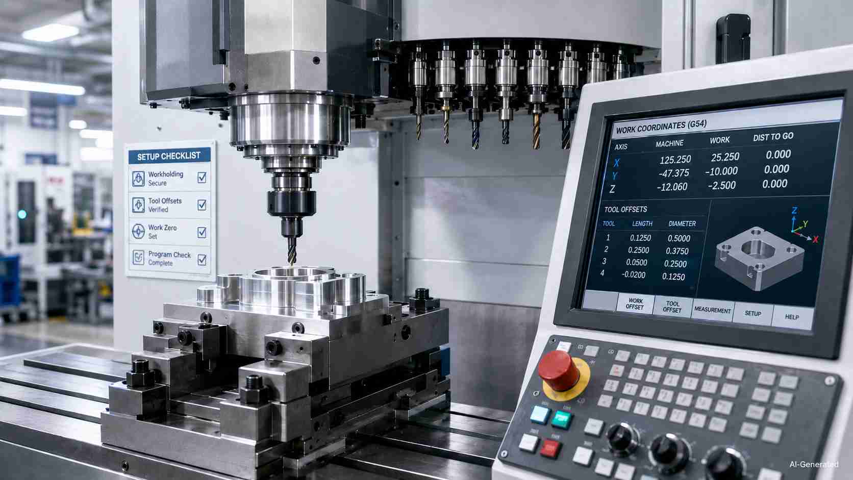
CNC setup with fixture, tools, and control screen
Before a shop trusts a cycle, CNC setup brings the job plan, machine, cutter package, and part location into agreement. CNC machine setup is not a prelude to production but the point where quality habits begin, which gives teams fewer surprises, steadier batches, and parts that remain close to print from approval through run completion.
What Is CNC Setup?
CNC machine setup is preparing machine conditions, cutting tools, coordinate values, and workholding before production machining begins. It aligns the shop-floor state with part needs.
Why Setup Quality Affects Production Performance
Poor setup conditions often appear later as dimensional drift, unstable cutting, or inconsistent first-part approval. Stable setup conditions improve repeatability, reduce scrap risk, and help maintain consistent machining behavior across production runs. Tools need to have known lengths, origins need to have predictable values, and the workpiece has to have stable support before stable production machining begins.
CNC setup vs CNC programming
Programming defines tool motion digitally, while setup translates that data into physical machine conditions on the shop floor. Even a correct NC program can fail if offsets, fixturing, or coordinate references are set incorrectly on the machine. CNC programming writes the motion, but setup makes the machine ready to carry that motion safely on the actual part. Programming defines motion logic, while setup establishes the physical conditions that allow those programmed moves to produce the intended geometry.
How to Set Up a CNC Machine (Step-by-Step)
Step 1: Prepare the Fixture and Workpiece
CNC setup moves in a planned order, beginning with the fixture. The part is located, clamped, and checked against the intended machining path. Thin-wall parts may require softer clamping pressure or additional support points before roughing begins.
Step 2: Load Tools and Set Tool Offsets
After fixture preparation, the setup moves to the cutting tools. Each cutter is loaded, measured, and linked to its recorded offset value inside the control.
Many shops verify tool length with presetters or spindle probes because even small offset errors can shift drilling depth or shoulder location across the batch.
Step 3: Establish the Work Coordinate System
The datum links the drawing to the machine's travel. Operators confirm that programmed locations match the physical part position instead of relying on assumed reference values.
Incorrect work offsets remain one of the most common setup-related problems, especially after fixture changes or re-clamping operations.
Step 4: Verify Program Motion and Machine Travel
After the work coordinate is confirmed, the machine path is reviewed before cutting begins. Dry-run checks help identify unexpected travel, holder interference, and clearance problems while the spindle remains above the material.
Multi-axis setups usually require additional verification because tool orientation changes continuously during rotary motion.
Step 5: Run a Dry Cycle Before Cutting
Many shops reduce rapid override during the first cycle while monitoring spindle approach, retract height, and fixture clearance.
Single-block execution is sometimes used near tight areas where holder collision risk increases.
Step 6: Inspect the First Part Before Production Release
The first approved part establishes the baseline condition for production. Critical dimensions, datum relationships, and visible surface conditions are checked before continuous machining begins.
Offset corrections are normally recorded immediately so the setup condition can be repeated later in the batch.
How CNC Setup Influences Machining Accuracy
Fixture Rigidity and Part Movement
When the fixture lacks stiffness, the part may shift under cutting pressure, and the cutter begins chasing a moving target. Moreover, in the context of CNC setup, that motion appears as size drift, chatter marks, and uneven walls, not as a program mystery.
Tool Runout and Cutting Accuracy
A cutter that wobbles around its centerline removes material unevenly, which can change hole size, edge quality, and finish from one feature to the next. Better holder control improves cutting stability and surface consistency.
Datum Misalignment and Tolerance Stack
If the selected origin is slightly misaligned, every related feature inherits that positional error. In that case, every associated feature will inherit that bias. Not only that, but chained dimensions may start to crowd the allowable tolerance zone before inspection identifies the pattern. Even small datum shifts can move multiple related features simultaneously, creating positional errors that accumulate across the part rather than affecting only one dimension.
Setup Repeatability Across Production Runs
In repeat production, consistent CNC setup practices help prevent drift in tool data, work offsets, and clamping conditions. This consistency safeguards surface quality, positional match, and part-to-part outcomes when the project is returned. In many general CNC milling operations, stable setup conditions help maintain surface finishes in ranges such as Ra 3.2-6.3 µm, although actual results still depend on tooling, material, and cutting parameters.
CNC Setup Strategies for Different Machining Operations
CNC Milling Setup Considerations
In milling, the most important thing is to protect the prismatic stock from side loads while maintaining the reachability of the machined faces. Milling setup usually focuses on vise alignment, reference-edge selection, and cutter access before machining begins.
CNC Lathe Setup and Workpiece Support
Next comes the lathe, where round stock, chuck grip, center support, and bar extension are effective. Shops decide how to set up a CNC machine for rotation, pressure, and length control.
Multi-Axis CNC Setup Challenges
Multi-axis work adds another layer, as the tool approaches from changing angles and the fixture must leave enough room for motion without contact between holder, spindle, stock, or clamps.
Prototype, Low-Volume, and Production Setup Strategies
With the transition from one-time work to recurring batches, the approach changes. Prototypes embrace flexible holding and additional checks, low-volume projects strike a compromise between reuse and adjustment, and production work uses established routines for reliable output.
Common CNC Machine Setup Problems
Incorrect Tool Offsets
Incorrect tool offsets make the control act on false cutter data. A CNC setup mistake like this can leave depths, shoulders, or bores away from the drawing target before anyone expects trouble.
Poor Workholding Stability
When clamping force or contact support is weak, the component can creep under load, which gives production a mix of scrap, rework, and inspection delays instead of steady output. In many CNC setups, stable part positioning depends heavily on proper fixture selection and CNC workholding strategy during machining.
Misaligned Datum References
A misplaced datum sends every related move from the wrong reference. It makes several dimensions appear wrong, even when the toolpath itself was written with care.
Excessive Tool Overhang
Too much overhang lets the cutter deflect and vibrate, which might show up as taper, chatter, rough texture, and shortened tool life during an otherwise normal cycle.
Setup Errors in Multi-Operation Machining
When a component is re-clamped or re-oriented, setup error can accumulate with the CNC machine setup over the course of several operations. Errors introduced during re-clamping can accumulate across operations and make later inspections more difficult.
Verifying CNC Setup Before Production
Verifying Tool Offsets and Tool Condition
Verification begins with the data from the tool. Prior to the beginning of a batch, setup verification begins with tool data review on the length, diameter, wear entries, and condition of the cutter. This helps detect damaged tools or incorrect offset values before production starts. For example, finishing operations such as reaming may remove only a small amount of material, sometimes around 0.1-0.5 mm, depending on hole size and process requirements.
Confirming Fixture Alignment and Clamping
Next, the fixture gets reviewed for location, clamp contact, and holding pressure. It gives the workpiece stable support before cutting forces are applied.
Checking Coordinates and Program Alignment
Then, the CNC machine setup review links the work origin with programmed motion, which makes sure that the path, stock location, and machine reference agree before the cycle begins.
Dry Runs and First-Part Inspection
After that, a dry run is carried out to preview motion without cutting, and then a first-part inspection is executed to verify that the opening piece is in accordance with the specifications. This allows the batch to proceed with a lower chance of scrap and improved repeatability.
CNC Machine Setup Checklist
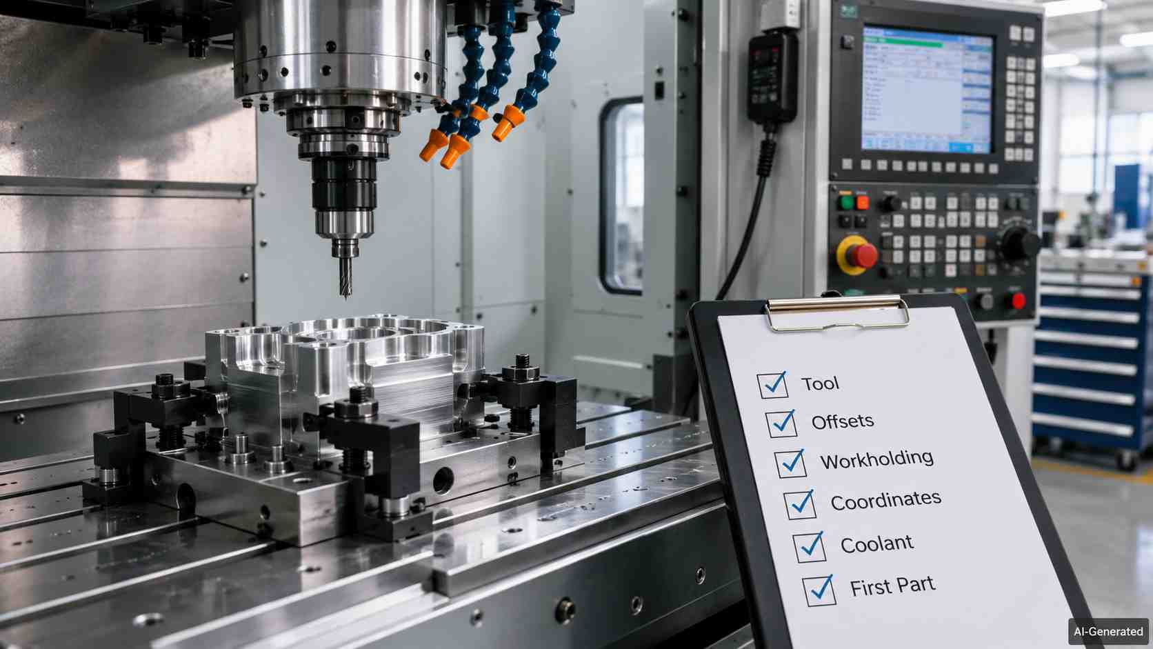
CNC machine setup checklist with clamped workpiece
Tool Installation and Offset Verification
Setup checklists usually begin with tool holders, inserts, gauge lengths, and wear offsets before the machining cycle starts. As a result, this transforms the CNC setup into a documented control point rather than a memory test.
Workholding and Clamp Inspection
The next check follows the part itself, which asks whether jaws, stops, screws, and pressure locations hold the material without marking or bending it during cutting load.
Datum and Coordinate Confirmation
Then, the CNC machine setup checklist establishes a connection between the drawing origin and the controller values. It offers the operator one more opportunity to identify any shifting reference selections, incorrect work offsets, or swapped zeros that may have occurred.
Coolant, Clearance, and Dry Run Checks
Once the part and numbers agree, coolant flow, chip path, travel space, and dry-run motion get reviewed together, which helps reveal interference before the cutter commits to material.
First-Part Validation Before Production
The final checkpoint belongs to the first part. Measured results are compared with drawing needs, adjustments are recorded, and only then does the job earn release for repeat pieces.
Reducing CNC Setup Time in Production
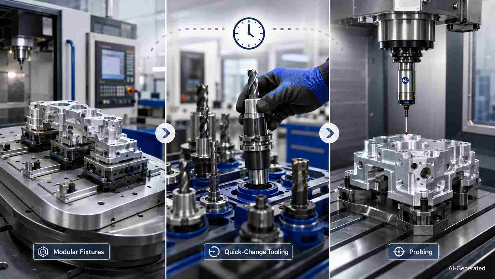
Reducing CNC setup time with fixtures, tools, and probing
Modular Fixtures and Change-Ready Tooling
Modular fixture plates, preset holders, and reusable locators speed up the changeover process by enabling teams to maintain known positions from one project to the next. In the context of CNC setup, time savings happen through repeatable hardware rather than through hasty judgment. Some setup-optimization studies have reported setup-time reductions of roughly 20-30% after fixture and workflow improvements.
Changeover Reduction Between Operations
Between operations, shops save minutes by grouping shared cutters, staging the next holding package, and moving preset tasks away from machine downtime.
Probing and Automated Assistance
Probes can locate stock, measure tools, and update work values inside the control. Hence, it provides the CNC machine setting with a measured start with fewer manual checks.
For repeat production and complex fixtures, setup planning is often reviewed together with cutter access, tolerance requirements, and workholding strategy during DFM evaluation.

Precision CNC Machining Service
Professional manufacturing, fast turnaround, and quality assurance.
How Machine Capability Affects Setup Stability
Machine Rigidity and Thermal Stability
A capable frame resists cutting load without flex. Meanwhile, controlled warm-up limits thermal drift. That gives CNC setup a steadier platform for size control across the run.
Spindle Precision and Axis Accuracy
Additionally, spindle motion and axis geometry are responsible for determining whether or not commanded positions land where inspection anticipates them to. Location drift, taper, and pattern error are all reduced when runout is reduced and verified travel is performed.
Tool Holder Systems and Runout Control
Poor holder condition or taper contact can increase runout and reduce cutting consistency. Accurate taper contact, collet condition, and shorter gauge length limit eccentric cutting, which helps protect edge wear, roundness, and surface texture.
Automation and Probing Systems
Probes and automated checks add measured feedback when setting up a CNC machine. Thus, operators confirm part location and tool status inside the control before repeating work proceeds.
Collision Prevention During CNC Setup
Holder Clearance and Fixture Interference
Many setup collisions happen before cutting starts. The spindle clears the part in CAM simulation, but the holder body contacts a clamp, vise jaw, or fixture corner once the real setup is loaded onto the machine.
This becomes more sensitive in deep-pocket milling and multi-axis machining. A 12 mm end mill may appear safe in the toolpath, yet the holder diameter behind the cutter can still strike nearby geometry during tilt motion or rapid positioning.
Setup review usually checks:
- holder diameter
- gauge length
- clamp height
- spindle approach angle
- clearance during retract moves
Small fixture changes sometimes solve the issue faster than changing the cutter itself.
Dry Runs and Single-Block Verification
Dry runs are commonly used before first-part cutting, especially on new fixtures or revised programs. The machine executes motion above the workpiece while the operator watches axis travel, retract height, and spindle approach behavior.
Many shops reduce rapid override during initial setup. Some also use single-block execution near tight areas where the holder passes close to clamps or finished walls.
This is especially important in 5-axis machining because rotary movement changes tool orientation continuously. Clearance that exists at one angle may disappear after table rotation.
Coordinate Errors and Overtravel Risk
Incorrect work offsets remain one of the most common setup-related collision causes. A misplaced Z zero or wrong work coordinate can drive the spindle into the fixture before the operator notices abnormal movement.
Large parts increase the risk further because axis travel becomes less visually obvious near machine limits.
Setup verification often includes:
- work offset confirmation
- machine home position checks
- soft-limit review
- safe retract position validation
- simulation comparison against the actual setup orientation
Even stable machining programs can fail if setup coordinates do not match the physical part location on the machine.
Multi-Axis Collision Complexity
Collision risk rises in simultaneous 5-axis machining because the spindle, holder, rotary table, and fixture all move through changing positions during the cycle.
A setup that works in vertical cutting may lose clearance once the B-axis tilts or the C-axis rotates toward the fixture.
Because of this, many multi-axis setups are reviewed with:
- digital simulation
- machine kinematic verification
- holder-envelope checks
- shortened gauge lengths where possible
Some aerospace and mold setups also reserve additional clearance margins near tall fixtures because slight positioning variation during rotation can reduce available space unexpectedly.
Conclusion About CNC Machine Setup
CNC setup continues to affect machining after production begins. Fixture rigidity influences how the part reacts under cutting load. Offset accuracy changes whether features stay on location. In multi-operation work, small setup errors may accumulate after each re-clamping step.
Many machining problems do not begin in the NC program itself. A work offset that is slightly misplaced can shift the entire part. Excessive tool overhang may introduce vibration that only appears during finishing passes or deep-pocket cutting.
For complex CNC parts, setup planning is often reviewed together with cutter access and inspection requirements before production release. JLCCNC reviews these machining conditions during DFM evaluation for both prototype and production machining work.
Upload your CAD file to get a fast quote starting from $1, with lead times as short as 3 days.
Precision CNC Machining Service
Professional manufacturing, fast turnaround, and quality assurance.
FAQ About CNC Machine Setup
Q: What is CNC machine setup?
It is the shop-floor preparation that readies equipment, cutters, holding, coolant, and reference values before a job enters production. Think of it as the handoff from plan to controlled cutting.
Q: Why is CNC setup important for machining accuracy?
Accuracy begins before the first chip. When tools, workholding, and coordinates agree, the machine has a better chance of making each feature match the print.
Q: What is included in a CNC setup checklist?
A useful checklist covers cutter loading, offset review, fixture condition, work origin, coolant delivery, travel space, and first-piece approval before batch work starts. Standard CNC machining tolerances are often around ±0.1 mm for general features unless tighter requirements are specified.
Q: How do tool offsets work in CNC machining?
Tool offsets tell the control how far a cutting edge is from the programmed reference, which allows different tools to cut depth and location without rewriting the program.
Q: What causes setup errors in CNC machining?
Most errors come from wrong values, loose holding, poor alignment, worn cutters, or missed handoff notes. Remember, each one can move a part away from drawing intent.
Q: How can setup time be reduced in production machining?
Shops reduce changeover by using repeatable fixtures, preset tools, organized carts, probing, and documented routines that remove assumptions from repeated jobs.
Q: How long does CNC setup take?
Setup time depends on part shape, machine type, fixture needs, cutter count, inspection level, and operator familiarity. It can be from minutes for repeated work to hours for demanding jobs.
Keep Learning
Laser Engraving Aluminum: Marking Methods & Surface Effects
Key Takeaways Laser engraving usually removes base material to create a recess. Laser marking is a broader term that can describe a surface-color change or material removal, so the process name alone does not define the final result. On aluminum, alloy and surface finish affect marking contrast. A light mark on dark anodized aluminum is a common design target, but the actual appearance depends on the finish and laser process. JLCCNC laser marking produces a recessed area 0.03–0.1 mm deep. The result i......
CNC Cutting Fluid: Types, Functions, Applications, and Selection Guide
Key Takeaways Cutting fluid in machining performs four functions simultaneously: cooling the tool and workpiece, lubricating the tool-chip interface to reduce friction, carrying chips away from the cut zone, and protecting machined surfaces from corrosion between operations. Different machining operations need different fluid priorities: high-speed aluminum milling may need adhesion control and chip evacuation, threading and tapping need strong lubrication, and grinding requires both cooling and fine ......
Blind Hole Machining Guide: What Is a Blind Hole, Types of Holes, and Tapping Tips
What Is a Blind Hole? Types of Holes and CNC Hole Machining Explained In CNC machining, few operations challenge process control and tool stability as much as blind hole machining. A blind hole is a hole that terminates at a defined internal depth rather than breaking through the opposite surface. Because the cavity is enclosed at the bottom, chip evacuation, thermal behavior, tool wear, and dimensional accuracy become far more difficult to manage compared to through-hole machining. These constraints ......
Rake Angle in Machining: Machinists’ Guide to Perfect Cuts
What is Rake Angle? (minaprem) If you've ever stood in front of a CNC machine or a manual lathe, you know that the cutting tool's geometry isn't just some arbitrary design. Every angle, edge, and surface has a job to do, and one of the most important of those is the rake angle. We've been running machines long enough to know that rake angle can make or break your surface finish, tool life, and machining efficiency. In this guide, we're going to walk you through what rake angle is, how it works, and ho......
Sheet Metal vs CNC Machining: A Guide to Choosing the Right Method for Your Metal Parts
Quick Answer: Choose sheet metal for uniform-thickness enclosures, panels, and formed brackets when bends and production volume support lower unit cost. Choose CNC machining for variable wall thickness, precision bores, tight feature relationships, and complex 3D geometry. Use a hybrid design when a formed structure needs precision-machined interfaces. A quote comes back for a bracket, and it's priced as a CNC part — machined from solid aluminum, a few hours of spindle time, a per-part cost that makes......
What Steps Are Taken To Minimize Waste In CNC Machining Processes?
How to Reduce Waste in CNC Machining: 5 Practical Strategies Quick Answer: CNC machining waste is reduced mainly through DFM, near-net stock, efficient toolpaths, preventive tool maintenance, and alloy-segregated recycling. The biggest gains usually come before cutting: reduce unnecessary material removal and prevent scrap or rework. Every CNC-machined part starts as more material than it ends up being. A pocket gets milled out, a profile gets cut away, a boss gets faced down to size — and all of that......