CNC Workholding: Methods, Best Practices, and Engineering Decisions
14 min
- What Is CNC Workholding?
- Engineering Principles Behind Effective CNC Workholding
- CNC Workholding Methods by Function and Application Context
- How to Choose the Right CNC Workholding Method
- Workholding Challenges in CNC Machining
- Best Practices for CNC Workholding Implementation
- FAQ
CNC workholding refers to the methods used to position and secure a part during machining. It directly affects part dimensions, alignment, and surface finish.
In practice, machining errors are rarely caused by the toolpath alone. More often, they originate from poor part positioning, uneven clamping, or material deformation under cutting forces.
For operations requiring tight tolerances, like ±0.01 mm, a stable and properly designed workholding setup is just as important as the machine’s spindle accuracy.
This article explains:
● How CNC workholding solutions maintain accuracy and part stability.
● How engineers select the right method based on part geometry, tolerance requirements, production volume, and other factors.
What Is CNC Workholding?
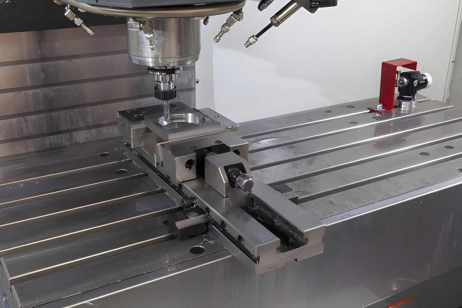
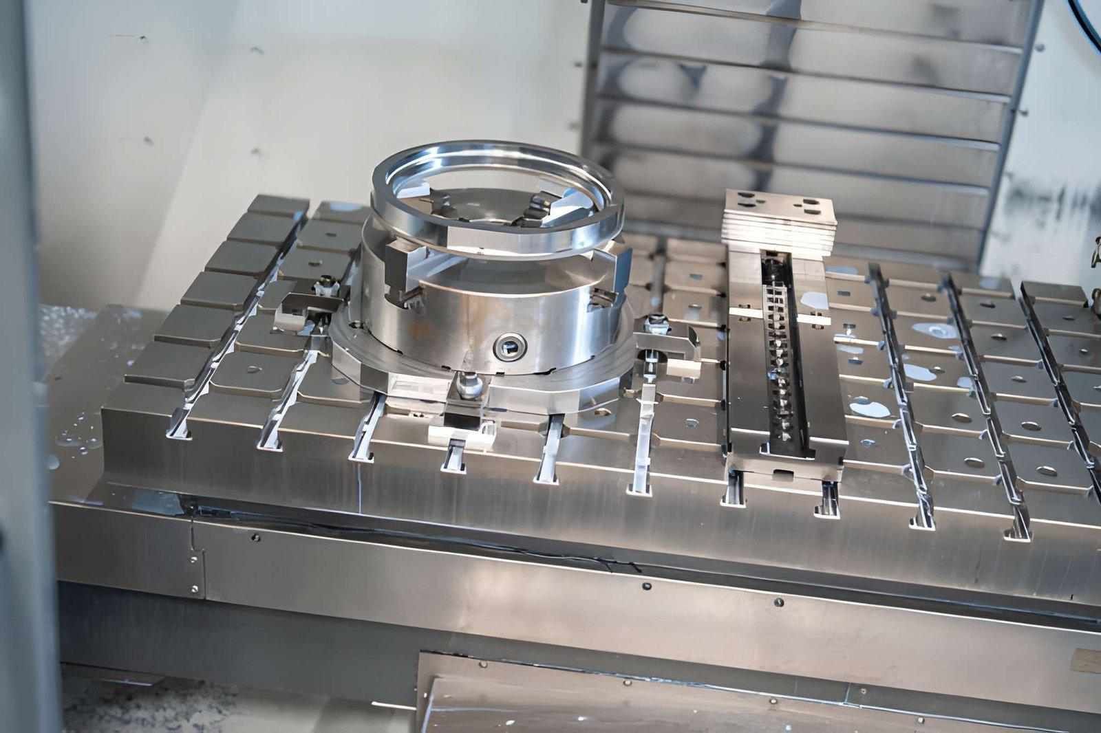
A metal part is being machined while securely fixed in a fixture mounted on the CNC machine table. (Source: iStock)
CNC workholding secures and positions parts during machining. It ensures high accuracy, repeatability, and safety. It is more than just clamping.
Effective workholding controls all potential movement. It keeps the part aligned with the machine axes and cutting tool. Even a slight shift can compromise dimensions, alignment, and surface quality.
An effective workholding setup includes three key elements:
● Part positioning: It sets datums and locks degrees of freedom so the part can’t move unexpectedly.
● Force resistance: It holds the part against cutting forces without lifting or sliding.
● Vibration suppression: It reduces chatter and small movements.
Why Workholding Is Not “Just an Accessory”
Workholding is often treated as secondary to tooling and programming. In general, it has a significant impact on part precision. A stiff end mill can’t fix a part that bends under clamping pressure. A perfect toolpath won’t help if the fixture lets the part move. When tolerances are tight or surfaces must line up across setups, workholding determines if the part will actually meet spec.
In many cases, dimensional errors originate from the fixture rather than the spindle.
Engineering Principles Behind Effective CNC Workholding
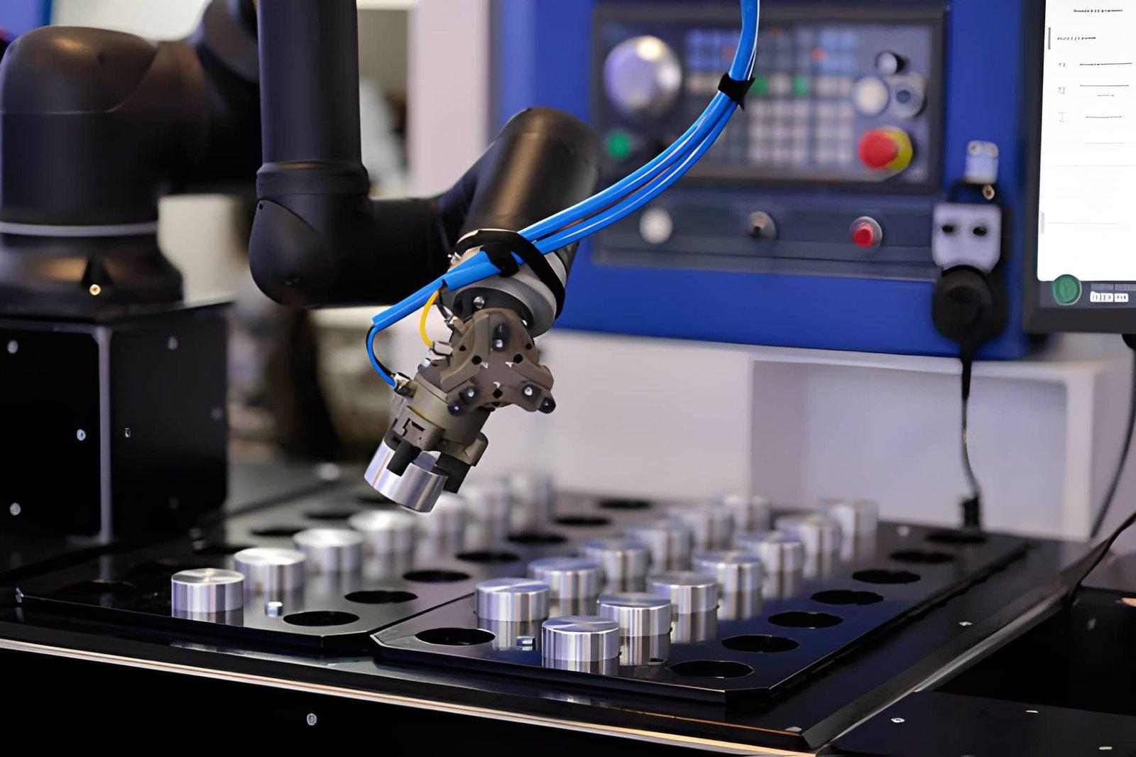
A robotic arm is automatically loading a workpiece into a CNC machine as part of an automated workholding. (Source: iStock)
In CNC machining, stable workholding restrains the part against cutting forces. This allows consistent geometry and repeatable tolerances.
Locating vs Clamping (Degrees of Freedom Control)
Any rigid body in space has six degrees of freedom: three translational and three rotational movements. Workholding must control all of them:
Locating defines where the part sits in space. Datums and reference surfaces are critical.
Clamping keeps the part there against cutting forces without over-constraining and deforming it.
3-2-1 Locating Principle in CNC Fixture Design
A widely used engineering method for controlling all six degrees of freedom is the 3-2-1 locating principle.
The concept works as follows:
● 3 points establish the primary datum plane
These points constrain movement along the Z-axis and rotation about X and Y.
● 2 points define the secondary plane
They restrict movement along one horizontal direction and rotation about Z.
● 1 point locks the final degree of freedom
This prevents remaining lateral movement.
Together, these six contact points fully constrain the part without over-constraint.
Over-constraining a workpiece can introduce internal stress, distortion, or instability during cutting. The 3-2-1 method avoids this by applying only the necessary constraints to achieve geometric stability.
Proper 3-2-1 locating:
● Improves repeatability
● Ensures consistent re-clamping in multi-setup machining
● Reduces dimensional drift
● Enhances fixture reliability
When the locating is incomplete or incorrectly applied, even small cutting forces can cause micro-movement, directly affecting tolerance and surface finish.
Stability Under Cutting Forces
During machining, cutting loads act in different directions. To keep the part stable:
● Fully constrain the part to prevent movement.
● Place clamps and locators to resist the main cutting forces.
● Keep overhangs short to reduce deflection.
● Ensure fixture rigidity to maintain tight tolerances.
Deformation and Distortion Risk
When clamping thin or flexible parts, distribute the load uniformly to avoid deformation:
● Distribute force over a wide area.
● Use soft jaws or supports to stabilize the part.
● Apply force evenly to avoid twisting and bending.
Accessibility and Tool Path Clearance
The tool must not be obstructed by workholding. For example:
● Clamps, vises, or fixture pins must not interfere with end mills, drills, or probes.
● Define the proper tool approach, path, and spindle speed.
● Modular or adjustable fixtures are used to access deep pockets and complicated shapes.
In cases of limited tool clearance, operators resort to changing feed, speed, or approach angle to finish the cut. These changes may impact stability and cause vibration or dimensional change.
CNC Workholding Methods by Function and Application Context
CNC workholding must hold the part securely without causing distortion. Generally speaking, fixture choice depends on:
● Part geometry
● Material properties
● Production requirements
Here are the common ways of workholding from a function and application standpoint.
Mechanical Workholding (Vise, Jaws, Clamps)
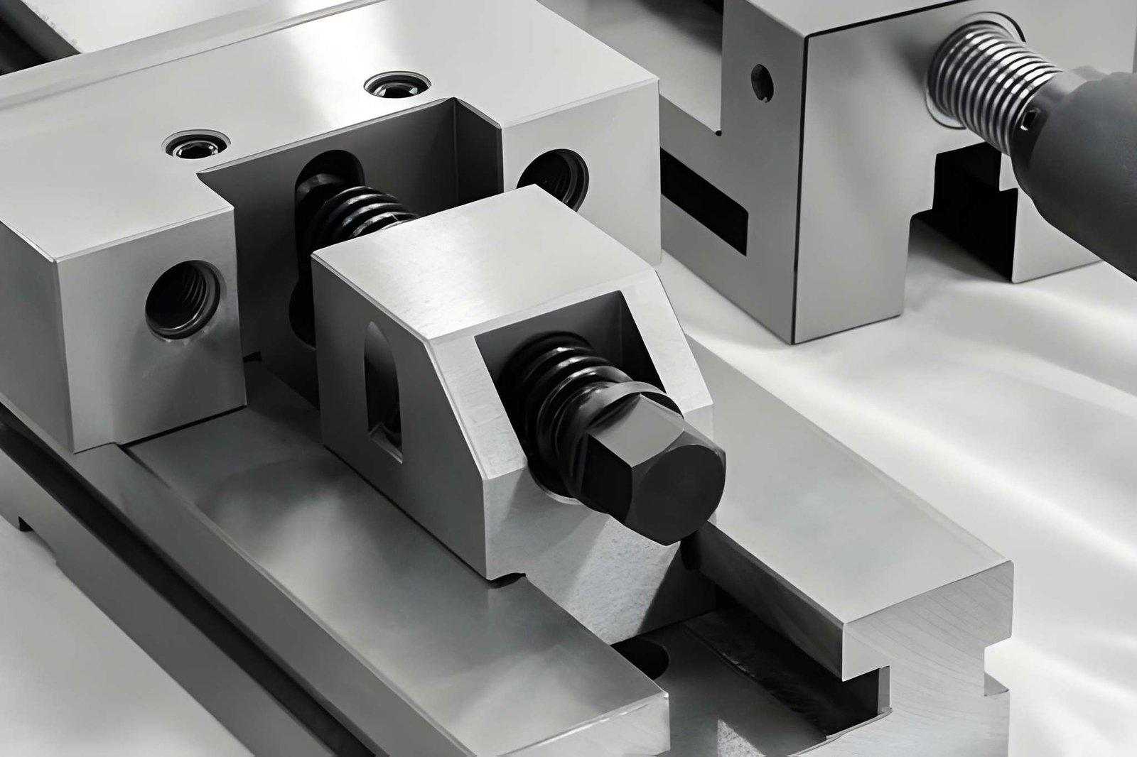
The image depicts a fixture used to hold metal parts. (Source: iStock)
Mechanical systems provide baseline rigidity and versatility. They are ideal for parts that:
● Require standard positioning and high resistance to lateral and vertical cutting forces.
● Can tolerate usual clamping points without risk of deformation.
● Need quick setup and frequent changeovers.
Mechanical workholding is ideal for medium-sized parts in low- to medium-volume production. It offers high rigidity and allows easy part access for machining.
Fixture-Based Workholding (Dedicated & Modular Fixtures)
Fixture systems secure parts and allow repeated setups, particularly in medium- and high-volume production. These:
● Keep parts/components positioned consistently.
● Reduce setup time for recurring operations.
● Support complex shapes that standard clamps cannot hold.
Modular fixtures can be reconfigured to fit various parts so that they can be used in small batches or variable production runs. On the other hand, dedicated fixtures are designed to handle only one component. However, they offer optimum rigidity and shorter cycle times.
Vacuum and Magnetic Workholding
Vacuum and magnetic systems are suited for thin, fragile, and surface-sensitive parts. They address issues like:
● Clamping without inducing distortion and marring surfaces.
● Securing parts that lack robust clamping points.
● Allowing high-speed machining with minimal interference.
These workholding methods work well for fragile components, including sheet metal, composites, and parts with finished surfaces.
Custom Machined Workholding Solutions
Custom workholding is required for intricate geometries or when tight tolerances are critical. These are designed for situations where standard equipment falls short. They typically:
● Support irregular or intricate shapes.
● Maintain precision across multiple axes.
● Reduce deformation in thin-walled or flexible components.
Technical Comparison of CNC Workholding Methods
| Method | Rigidity | Setup Speed | Best For | Limitations |
| Mechanical Vise & Clamps | High | Fast | General machining, rigid parts | May deform thin walls |
| Modular Fixture | Medium–High | Moderate | Multi-part production | Slight rigidity trade-off |
| Dedicated Fixture | Very High | Very Fast (after setup) | High-volume production | High upfront cost |
| Vacuum Workholding | Low–Medium | Fast | Thin plates, surface-finish parts | Limited cutting force resistance |
| Magnetic Workholding | Medium | Fast | Ferrous flat parts | Not suitable for non-ferrous materials |
Selecting the correct method depends on the balance between rigidity, distortion risk, setup efficiency, and production volume.
How to Choose the Right CNC Workholding Method
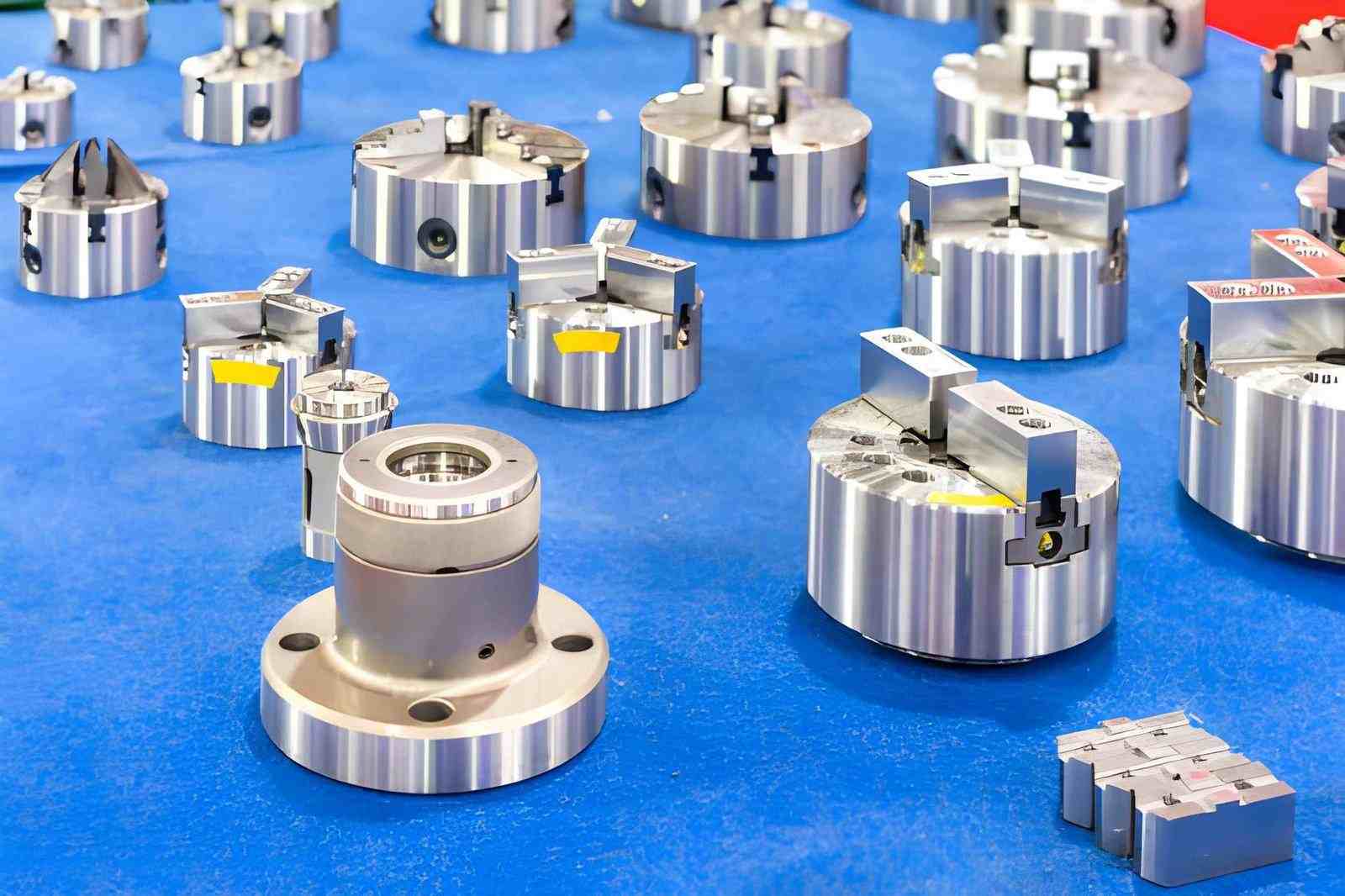
Various lathe chucks and tool holders are arranged on a table. (Source: iStock)
The right workholding solution relies on the part geometry, the material characteristics, tolerance requirements, production volume, and the intended machining plan. Even with ideal tooling and optimized CAM programs, poor workholding decisions can lead to deflection, vibration, and scrap.
Material and Part Geometry Constraints
Workholding requirements are driven by part geometry and material behavior.
● Slim, flexible, or thin components require distributed support because overtightening will lead to the possibility of bending and warping.
● Irregular geometries or deep areas are sometimes suited to custom locators or machined supports since the common vises may not support them.
● Thick and rigid components are generally easier to clamp. However, uneven clamping can still distort critical surfaces.
● Ribs, bosses, and pockets often restrict where clamps can be placed safely without interfering with the cut.
Precision and Repeatability
Tolerance requirements determine the choice of the fixtures:
● Tight tolerances (+/-0.01-0.05 mm) require sturdy fixturing, fine positioning, and regulated clamping forces.
● Areas of the part that need consistent machining should be positioned the same way each time. Modular or dedicated fixtures are better than ordinary vises for this purpose.
● Even when toolpaths and spindle performance are flawless, a frequent cause of scrap is inconsistent clamping or ineffective datum referencing.
Production Volume and Setup Efficiency
Volume affects whether rigidity or flexibility is prioritized:
● High-volume production runs take advantage of dedicated fixtures. This reduces setup time, improves repeatability, and limits operator variation.
● Mechanical vises, modular fixtures, or adjustable clamps are commonly used in low- to medium-volume production. These are flexible but require careful setup.
● Reducing manual adjustments helps minimize tolerance variation between setups.
Cost, Flexibility, and Changeover
Fixture decision must keep a balance between performance and economics:
● Dedicated fixtures cost more initially but reduce per-part cycle time and setup variation.
● Modular fixtures are flexible for multiple part types but may compromise some rigidity.
● Mechanical clamps are inexpensive and versatile. However, they can introduce variation on complex or precision components.
● Custom fixturing is justified only when standard methods cannot achieve the required tolerances, stability, and accessibility.
Integration with CNC Machining Strategy
A metal part is set up on a milling table for precise machining. (Source: iStock)
Workholding needs to conform to the machining plan:
● Clamps and locators must allow full tool access, such as deep pockets or paths in more than two axes.
● Take into account the overhang, the spindle angle approach, and cutting directions to avoid deflection and vibration.
● The fixture design needs to be finished before CAM programming to prevent rework.
● Thermal effects and cutting forces must be considered, particularly on the long, thin, or soft parts.
Workholding Challenges in CNC Machining
Even a high-quality machine and optimized tool paths may not be able to counteract a shifting, bent, or vibratory part. Most tolerance problems originate from the fixture. The identification of common workholding issues helps you to reduce scrap and ensure efficient production.
Thin-Wall and Flexible Parts
Thin sections bend or vibrate under clamps and cutting forces.
● Over-tightening jaws can bend walls or ribs.
● Unsupported long, narrow sections chatter during CNC milling and drilling.
● Soft materials shift or compress under clamps, misaligning holes or edges.
Fix:
● Use soft jaws, distributed support, and vacuum/magnetic hold-downs to protect the part.
● Position clamps along the stiffest and strongest axes for stability.
● Minimize overhangs and avoid point-loading on thin or flexible features.
Multi-Setup and Re-Indexing Accuracy
Parts needing multiple setups often fail because they don’t return to the same position.
● Every reclamp introduces small shifts.
● The effects associated with misaligned datums include concentricity and alignment errors in shafts and bores.
● The risk increases when using rotary tables or multi-axis setups if the locating points are not positioned correctly.
Fix:
● Use kinematic locators, machined datums, and dedicated fixtures. Moreover, you must always verify alignment after each setup.
● Consider any distortion introduced by the fixture when positioning the part.
Repeatability in Batch Production
Even small setup differences add up across a batch:
● Jaw position, clamp torque, or fixture wear vary between parts.
● Thermal expansion over long runs changes dimensions slightly.
● These small errors can push parts out of tolerance, especially for holes and flat surfaces.
Fix:
● Standardize torque and clamp placement.
● Inspect fixtures regularly.
● Use dedicated or modular fixtures for consistent part positioning.
Excessive or Insufficient Clamping Force
Improper clamping force — whether excessive or insufficient — leads to both obvious and subtle failures. For instance:
● The excessive force can bend thin walls, distort holes, or strain the material.
● Insufficient force will result in the part lifting or moving. This leads to chatter, taper, and surface marks.
● Both conditions affect size, alignment, surface finish, and tool life.
Fix:
● Match clamping force to material, wall thickness, and cutting load.
● Use torque-controlled clamps and calibrated fixtures.
Best Practices for CNC Workholding Implementation
Tolerance control largely depends on the stability of the workholding system. If a part moves, bends, or vibrates, no optimized CAM or tool selection will fix it. Therefore, good practice starts before the first cut.
Plan Workholding Before CAM
● Decide how you’ll hold the part before programming.
● Identify all datums and surfaces that need support.
● Make sure clamps and locators don’t block the spindle or tools.
● Consider multi-setup parts: the fewer times you reclamp, the less risk of error.
● Contemplate cutting forces and part overhangs while planning fixtures.
Tip:
● If you wait until CAM is done, you’ll compromise either access or part accuracy.
Use Soft Jaws and Custom Fixtures
Standard vises aren’t always enough.
● Soft jaws fit irregular shapes and protect thin and delicate features.
● Custom-machined fixtures support long or flexible parts to prevent bending.
● Machined locators make multi-setup parts repeatable.
Tip:
● Always test-fit the part before cutting because even a fraction of a millimeter misalignment can ruin a batch.
Check Clamping Force and Stability
Clamps must match the part, not just be “tight.”
● Measure torque at every setup, manual variations, and shift parts.
● Check the part after clamping for bends or lift.
● Perform a light test cut first to spot vibration.
● For repeatable setups, consider torque-controlled or hydraulic clamps.
Tip:
● Too high a force bends the part; too low lets it slide. Both can impact tolerances.
Design for Workholding
● Parts should be designed with holding in mind.
● Flat, accessible surfaces make clamping simpler.
● Ribs and reliefs stiffen thin walls.
● Avoid protrusions that block clamps.
● Include consistent datum surfaces for multi-setup alignment.
Tip:
● Make small design changes early to simplify fixture work later.
● Additionally, early adjustments help reduce scrap.

At JLCCNC, custom fixtures and soft jaws are designed alongside the machining strategy to ensure:
● Controlled clamping forces
● Reduced deformation risk
● Improved repeatability in batch production
Integrating fixture design with machining planning helps reduce scrap and maintain dimensional consistency across production runs.
Ultimately, workholding is not a secondary decision in CNC machining. It is a structural factor that directly determines dimensional stability, repeatability, and production efficiency.
The right fixture strategy often separates consistent production from recurring tolerance failures.
FAQ
What are the differences between workholding and clamping in CNC machining?
Workholding is the entire system that holds a part in position. It comprises locators, supports, and clamps. Clamping, on the other hand, is simply the force that holds the part. A part can still shift even when tightly clamped if the locators are poorly positioned.
What influences the machining accuracy due to workholding?
Any movement, vibration, or bending alters dimensions and surface finish. Misaligned holes, edge chatter, or tolerances lost tend to begin at the fixture.
Which workholding technique is right for thin-wall components?
Thin-wall components require distributed support and controlled clamping force. Soft jaws, custom-machined supports, vacuum tables, or padded clamps are commonly used. Point clamping should be avoided, as it can cause bending or post-machining spring-back. The goal is to stabilize the part without introducing deformation.
How can you calculate the clamping force?
Clamping force must exceed the estimated cutting force while remaining below the deformation threshold of the material. Engineers typically consider:
● Estimated cutting forces
● Friction coefficient between the part and fixture
● Contact area and wall thickness
● A safety factor for vibration and tool load variation
In practice, torque-controlled or hydraulic clamps are used to maintain consistent and repeatable force without over-tightening.
Is vacuum workholding a replacement for mechanical fixtures?
Vacuum tables are mainly used on thin and flat, or delicate parts. Mechanical or custom fixtures are still required on heavier or irregular parts. Vacuum systems are assistive technologies and rarely replace proper mechanical fixturing entirely.
Popular Articles
• Cutting with Precision: A Comprehensive Guide to CNC Water Jet Technology
• CNC Coolant Explained: Types, Maintenance & Safety
• Rake Angle in Machining: Machinists’ Guide to Perfect Cuts
• What Steps Are Taken To Minimize Waste In CNC Machining Processes?
• How EDM Wire Cutting Works: Complete Guide to Precision CNC Wire Cutting
Keep Learning
Chatter in Machining: Causes, Effects, and How to Reduce It
CNC milling operation producing visible chatter marks on an aluminum workpiece Quick Chatter Diagnosis Checklist Symptom Most Likely Cause First Action High-pitched squeal Regenerative chatter Change spindle speed ±15% Chatter only in deep pockets Excessive tool overhang Shorten tool Chatter on thin walls Low workpiece rigidity Improve fixturing Chatter after tool replacement Runout / holder issue Check tool holder Chatter only during finishing DOC too small / rubbing Increase feed or adjust speed It ......
What Is Tool Offset in CNC? Types, Setup & Best Practices
CNC tool offset setup with measurement overlay Key Takeaways CNC offsets connect programmed intent with actual cutter position. Length data guides Z-axis depth control. Radius data protects part size during contour milling. Geometry values define the cutter's measured baseline. Wear values support fine correction during production. Verified data lowers scrap risk before full machining. Good offset habits protect tools, fixtures, and parts. In the context of CNC machining , tool offset is the quiet set......
Trochoidal Milling: Complete Guide to High-Efficiency CNC Machining
Key Takeaways Trochoidal milling combines circular cutter motion with continuous forward feed. The cutter normally engages 5 to 20% of its diameter instead of making a full-width cut. A smaller engagement angle limits force changes during slotting and pocket roughing. Low radial engagement often allows greater axial depths of cut than conventional slot milling. CAM software calculates the circular path automatically from the selected machining parameters. This strategy is widely applied to titanium, s......
What Is Die Casting? Process, Materials, and Applications
Key Takeaways Die casting is a metal casting process that forces molten metal into a reusable steel mold under high pressure, producing parts with tight tolerances and good surface finish at high volume. Aluminum die casting is the most common form by far, thanks to its combination of light weight, decent strength, and good corrosion resistance. The die casting process runs through mold preparation, injection, cooling, and ejection in a cycle that can repeat every few seconds to minutes depending on p......
First Angle vs Third Angle: Understanding Orthographic Projection Methods
Key Takeaways Orthographic projection is the system that lets a 3D part be represented through multiple 2D views, front, top, side, and so on. First angle projection and third angle projection are the two standard methods for arranging those views, and they place views in opposite positions relative to the object. First angle projection is the ISO standard used across most of Europe, India, China, Russia, and many other countries following ISO standards Third angle projection is the standard in the Un......
Micro EDM Machining: Capabilities, Materials, and Applications for Precision Components
Key Takeaways About Micro EDM Machining Only electrically conductive materials can be machined. Hole diameters can reach below 50 μm on specialized equipment. The process produces almost no mechanical cutting force, making it suitable for thin or delicate features. Surface integrity still requires attention because recast layers and heat-affected zones may remain after machining. Micro EDM is often combined with CNC machining, with milling producing the main geometry before EDM finishes critical micro......