Gear Machining: CNC Gear Cutting Processes, Accuracy Control, and Industrial Applications
16 min
- What Is Gear Machining?
- Gear Machining Processes Across the Gear Production Lifecycle
- CNC Gear Machining Workflow
- Key Factors Affecting Gear Machining Accuracy
- Typical Applications of CNC Gear Machining
- When CNC Gear Machining Is Not the Best Choice
- Key Takeaways for CNC Gear Machining
- FAQ
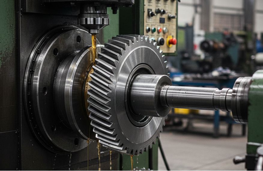
(AI generated) Gear hobbing process generating gear teeth on a steel gear blank using a CNC hobbing machine
A gear does not only need to meet nominal dimensional requirements. A gear has to carry a load smoothly and operate quietly at speed without causing accelerated wear or damage over millions of load cycles.
Gear machining is a precision manufacturing process that produces gears by cutting, refining, and finishing tooth geometry to ensure predictable load behavior, controlled accuracy, and long-term motion reliability in mechanical systems.
What Is Gear Machining?
Gear machining refers to a CNC-driven workflow that controls tooth geometry, load transfer behavior, and motion accuracy across multiple cutting and finishing stages.
Gear machining is not a single operation. It is a sequence of operations that shape, refine, and correct tooth geometry until the gear performs as intended in its final assembly.
The gear machining process is used to control a few critical outcomes:
● Tooth profile accuracy, which determines how evenly the load is shared across the gear face
● Pitch and spacing consistency, which directly affects vibration and noise
● Surface finish, which influences wear rate and heat generation
● Contact pattern, which decides whether the gear runs quietly or destroys itself over time
This is why gear cutting alone is rarely enough for anything beyond low-duty applications. You can machine a gear blank and cut teeth that meet nominal dimensions, yet still result in excessive noise, uneven wear, or premature failure during operation. The problems usually don’t show up during inspection; they show up after hours of operation.
From a functional standpoint, machining gears is about managing how force moves through rotating parts. If tooth geometry is even slightly off, the load concentrates instead of being distributed. This leads to localized stress concentration, increased heat generation, and, over time, surface pitting or tooth breakage. In high-speed or continuous-duty systems, those errors get loud before they get catastrophic.
CNC gear machining matters because it allows those variables to be controlled consistently. A properly machined CNC gear doesn’t just match a CAD model. It repeats the same contact behavior from part to part. Repeatability is the line between an experimental prototype and a piece of gear you can actually trust on a production floor. Producing a single functional gear is relatively straightforward; achieving consistent performance across large production volumes is significantly more challenging. At the end of the day, noise, heat, and efficiency all lead back to the precision of the tooth profile.
When the machining is dialed in, the gearbox is operating with minimal noise and vibration and runs for years. Even minor deviations can lead to progressive failure modes, including increased wear, elevated noise levels, higher long-term operating costs, and premature component replacement. This is the fundamental objective of precision gear machining: it reduces uncertainty in rotating motion by ensuring stable, predictable performance over the gear’s service life.
Gear Machining Processes Across the Gear Production Lifecycle
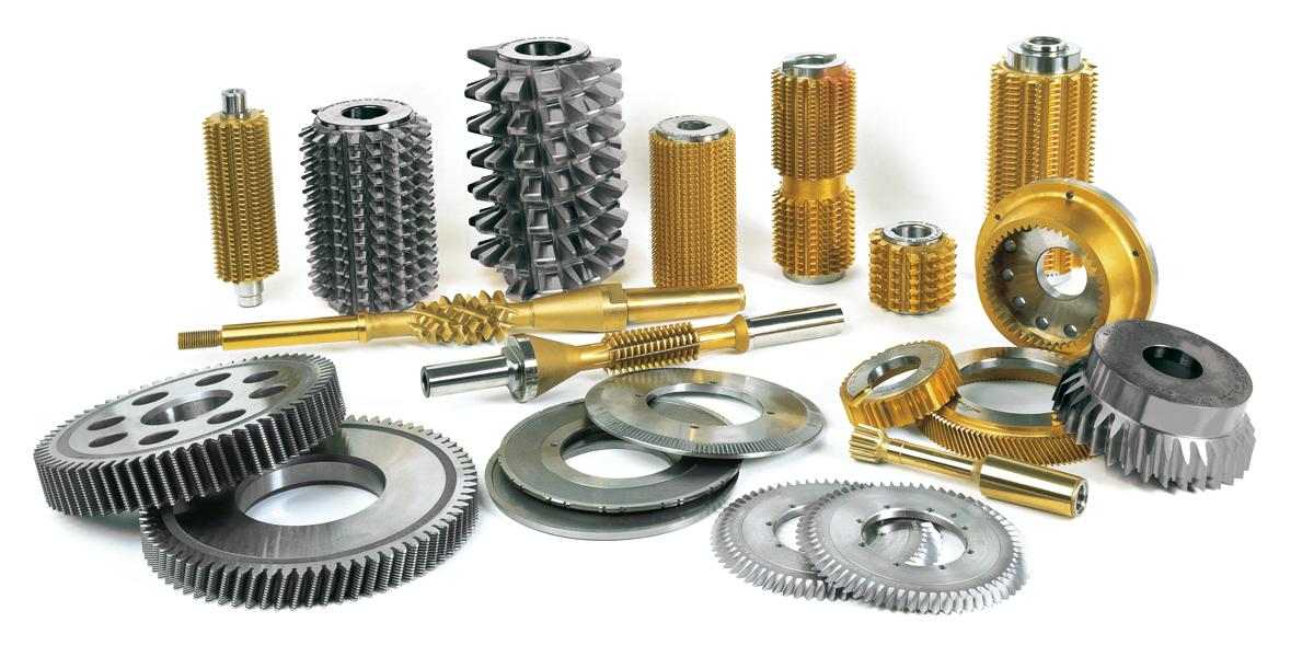
(Star Su) Steel gears at different stages of the gear machining process from cutting to surface refinement
Gear quality isn’t decided by a single machine or operation. It’s the result of how cutting, refinement, and supporting CNC work fit together across the entire production lifecycle. Each stage solves a different problem, and skipping or misapplying one usually shows up later as noise, wear, or inconsistent performance.
Gear Cutting Processes
Gear cutting is where tooth geometry is first introduced. This stage establishes tooth count, spacing, and basic profile, but it does not define final accuracy. Cutting gets the gear close; refinement makes it right.
Cutting accuracy is influenced by tool condition, machine rigidity, and how well the cutter motion matches the intended tooth geometry. Any error introduced here carries forward, which is why cutting strategy matters even if finishing operations follow.
Gear Tooth Generation (Primary Cutting Processes)
Primary generation processes create the tooth shape through synchronized tool and workpiece motion rather than simply carving a static profile.
●Hobbing is the most widely used method for machining gears in volume. The hob continuously engages the blank, producing smooth tooth spacing and good pitch accuracy. It’s efficient and flexible, but final accuracy depends heavily on machine stiffness and hob condition.
●Shaping uses a reciprocating cutter to generate teeth one space at a time. It’s slower than hobbing but allows internal gears and shoulder-clear designs that hobbing can’t handle. Shaping is often chosen for custom gear machining where geometry limits other methods.
●Broaching forms all teeth in a single pass using a progressive tool. Accuracy is high and cycle time is low, but tooling cost is high. This method only makes sense for high-volume, tightly controlled applications.
Gear Tooth Refinement (Accuracy & Surface Improvement)
Refinement operations exist to correct what cutting can’t fully control. This is where noise behavior, contact pattern, and load sharing are tuned.
●Gear shaving removes small amounts of material to improve tooth profile and spacing before heat treatment. It’s fast and cost-effective, but limited to softer materials.
●Gear honing improves surface texture and minor geometry errors after heat treatment. It’s commonly used when noise reduction is critical, such as in automotive transmissions.
●Gear grinding is the highest-precision refinement method. It corrects distortion from heat treatment and achieves tight tolerances on profile, lead, and surface finish. Grinding is slower and more expensive, but unavoidable for high-accuracy CNC gear applications.
CNC Operations Supporting Custom Gear Machining
Before and after tooth work, supporting CNC operations, determine whether the gear can actually function in an assembly.
Turning defines the gear blank’s concentricity, face width, and mounting surfaces. Any runout here directly affects tooth engagement, which is why precision CNC turning matters long before teeth are cut.
Milling is used for keyways, hubs, lightning features, and complex interfaces that integrate the gear into shafts or housings. Multi-axis CNC milling is often what determines whether the gear actually fits and functions in the final assembly.
Drilling and tapping add mounting and retention features, often requiring tight positional accuracy relative to the gear teeth.
In custom gear machining, these supporting operations are just as important as gear cutting itself. A perfect tooth profile won’t compensate for a poorly aligned bore or distorted hub.
Taken together, the gear machining process is less about individual tools and more about sequencing. Accuracy, noise performance, and lifespan depend on how each stage builds on the last, not on any single operation working in isolation.
CNC Gear Machining Workflow
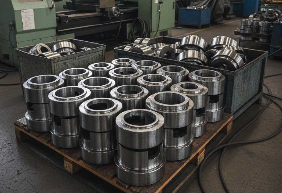
(AI generated) Prepared steel gear blanks ready for CNC gear machining in a production workshop
CNC gear machining follows a defined flow, but it’s not rigid. The order of operations and the decisions made at each step directly affect accuracy, cost, and whether the gear performs as intended once it’s in service.
The process starts with blank preparation. Raw material is turned to establish the bore, faces, and outer diameter. Concentricity is critical here. Any runout between the bore and the tooth form will show up later as uneven contact and noise, no matter how good the cutting operation is.
Once the blank is stable, the workflow moves into primary tooth generation. This is where hobbing, shaping, or broaching is selected based on gear type, volume, and geometry. At this stage, the goal is repeatable tooth spacing and a consistent base profile, not final surface finish. Decisions here balance cycle time against how much correction will be needed later.
If the gear requires heat treatment, it usually happens after initial cutting. Heat improves strength and wear resistance, but it also distorts the part. A good workflow plans for this distortion, instead of reacting to it after heat treatment. Allowances are built into earlier steps so refinement processes can bring the gear back into tolerance.
After heat treatment, tooth refinement comes into play. Shaving, honing, or grinding corrects profile errors, improves surface finish, and tunes the contact pattern. This is where gears transition from “dimensionally acceptable” to mechanically reliable.
Supporting CNC operations, such as milling keyways, drilling, or finishing hubs, are sequenced carefully around tooth work. Features that affect fixturing or alignment are typically completed before final tooth finishing to avoid introducing new runout.
The workflow ends with inspection and verification. Tooth profile, lead, pitch, and runout are checked against specification, often using gear measurement equipment rather than general-purpose metrology. This step validates not just dimensions, but whether the gear will transmit load smoothly under real operating conditions.
A well-designed CNC gear machining workflow isn’t about doing more steps. It’s about doing the right steps in the right order, so accuracy is controlled gradually instead of being forced at the end. That sequencing is what separates efficient production from costly rework in custom and high-precision gear manufacturing.
Key Factors Affecting Gear Machining Accuracy
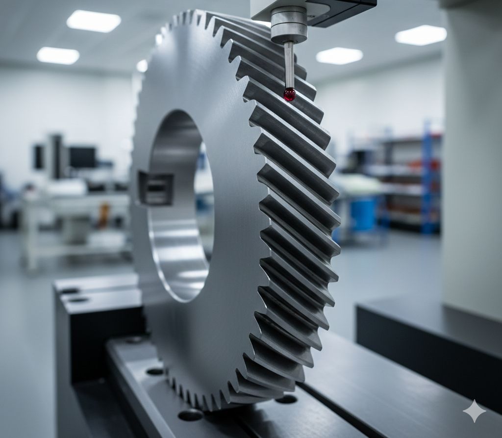
(AI generated) Inspection of gear tooth geometry using precision measurement equipment to verify machining accuracy
Gear accuracy isn’t controlled by a single machine or operation. It’s the combined result of design intent, machine behavior, and how materials respond throughout the machining process.
Tooth Geometry and Profile Control
The involute profile defines how gears transmit load. Even small deviations affect:
● Contact ratio
● Noise generation
● Load concentration
Gear machining accuracy depends on:
● Tool geometry consistency
● CNC interpolation accuracy
● Proper profile modification (crowning, tip relief)
Design intent matters here. Gears designed without realistic manufacturing tolerances often force downstream compromises that degrade performance.
Machine Rigidity and CNC Control Capability
Gear machining is highly sensitive to deflection and control lag.
Key influences:
● Spindle stiffness under cutting load
● Axis backlash and thermal stability
● Synchronization accuracy between rotary and linear axes
A rigid machine with mediocre control can outperform a high-end CNC if process stability is poor. For fine-pitch or hardened gears, even micron-level deflection shows up in tooth contact patterns.
Material Behavior and Heat Treatment Impact
Material choice affects every stage of machining.
Factors include:
● Machinability before hardening
● Distortion tendency during heat treatment
● Grindability after hardening
For example:
● Case-hardened steels require precise allowance planning
● Through-hardened materials limit post-treatment correction
● Powder metallurgy gears behave very differently from forged steel
Understanding material behavior allows engineers to design the process, not just react to defects.
Typical Applications of CNC Gear Machining
Industrial Machinery and Power Transmission Systems
Industrial equipment places some of the highest demands on gear accuracy due to continuous operation and high load cycles.
Common applications:
● Gearboxes for conveyors, crushers, mixers, and extruders
● Speed reducers in manufacturing lines
● Heavy-duty pumps and compressors
Functional requirements driving CNC machining:
● High load capacity with uniform tooth contact to prevent localized stress
● Consistent pitch accuracy to avoid vibration at operating speed
● Controlled lead and profile modifications to handle shaft misalignment and housing deflection
In these systems, gears often run for thousands of hours without shutdown. CNC-machined gears allow engineers to intentionally introduce crowning, tip relief, and lead corrections that compensate for real operating conditions, something impossible with loose tolerances or non-repeatable processes.
Automotive and Motion Control Components
Automotive and motion control applications demand a balance of precision, efficiency, and noise reduction, often at very high production volumes.
Typical components include:
● Transmission and differential gears
● Steering system gears
● Servo drive and actuator gears
Key functional drivers:
● Low noise, vibration, and harshness (NVH)
● High positional accuracy and repeatability
● Tight backlash control for smooth response
In motion control systems, even minor profile errors translate directly into positioning error, hunting, or resonance. CNC gear machining enables fine control over tooth geometry and surface finish, which is critical for servo-driven axes and precision automation equipment.
In automotive drivetrains, precision machining directly affects customer-perceived quality—gear whine and vibration are often traced back to microns of geometric deviation.
Custom Gears for Prototypes and Low-Volume Production
Not all gears are made in the thousands. Prototyping, R&D, and specialized machinery frequently require one-off or low-volume gears with non-standard geometry.
Typical use cases:
● Prototype transmissions and gearboxes
● Replacement gears for legacy equipment
● Specialized robotics or test rigs
Why CNC machining is essential here:
● Flexibility in gear geometry without dedicated tooling
● Fast iteration cycles during design validation
● Ability to machine complex or non-standard profiles
Multi-axis CNC milling and power skiving make it possible to produce functional gears without the cost and lead time of hobs or shaping cutters. While unit cost is higher, the ability to validate fit, function, and load behavior early often saves far more time and money downstream.
At this point, many gear projects hit a practical split.
The gear teeth may need specialized cutting, but the surrounding components—hubs, housings, shafts, and carriers—still demand tight tolerances and clean finishes.
That’s where high-precision CNC milling and turning actually carry most of the workload. Multi-axis milling for complex geometry, mill-turning for concentric features, and controlled surface finishing often matter just as much as the gear itself.
If you’re evaluating a real assembly and want to sanity-check manufacturability or cost before locking designs, getting a quick quote from a professional CNC shop is usually the fastest way to ground the numbers.
For prototype and low-volume gear projects, the biggest risk is not cost, but discovering functional issues too late.
Working with a CNC shop that understands both gear tooth geometry and supporting precision machining can shorten validation cycles and reduce redesign risk.
JLCCNC supports custom CNC gear machining alongside high-precision milling and turning, helping engineers validate fit, function, and manufacturability before scaling production.
When CNC Gear Machining Is Not the Best Choice
CNC gear machining is powerful, but it’s not universal. There are plenty of situations where it adds cost, time, or complexity without delivering real functional benefit. Knowing when not to use it is just as important as knowing when it’s essential.
High-Volume Commodity Gears
For gears produced in very high volumes with standardized geometry, CNC machining is often the wrong economic choice.
Typical examples:
● Appliance gears
● Consumer product gear trains
● Standard automotive auxiliary gears
Why CNC falls short here:
● Cycle time per part is too slow compared to dedicated processes
● Tooling amortization favors specialized machines like hobbing lines or molding
● Geometry is fixed, so flexibility offers no advantage
In these cases, dedicated gear hobbing machines, multi-spindle automatics, or even injection molding (for plastics) deliver far lower cost per unit once volume is high enough. CNC machining excels at flexibility, not mass repetition.
Loose Tolerance or Non-Load-Bearing Applications
Not every gear needs micron-level control. When loads are low and motion accuracy isn’t critical, CNC precision can be unnecessary.
Common scenarios:
● Light-duty timing mechanisms
● Manual adjustment systems
● Decorative or indexing components
Why CNC may be overkill:
● Tooth profile accuracy doesn’t affect function
● Noise and efficiency aren’t critical performance metrics
● Simple cutting methods already meet requirements
In these applications, basic gear cutting, laser cutting (for thin gears), or even stamping can be sufficient. Paying for tighter tolerances doesn’t improve performance; it just inflates cost.
Alternative Manufacturing Methods to Consider
Depending on volume, material, and performance requirements, several alternatives may be more appropriate than CNC gear machining.
Common options include:
● Gear hobbing for high-volume, standard gears
● Gear shaping for internal gears or shoulder-restricted designs
● Powder metallurgy for medium-load, high-volume gears
● Forging followed by finishing for high-strength applications
● Plastic molding for low-load, noise-sensitive systems
Each method trades flexibility for efficiency. CNC gear machining is strongest when geometry varies, tolerances matter, or volumes are low to medium.
Gear machining is only one piece of a working system. In real builds, performance and cost are often decided by everything around the gear, precision-milled pockets, accurately turned shafts, clean mating surfaces, and finishes that hold up in service.
If you already have drawings or just need a feasibility check, requesting a quote is the easiest way to see what’s realistic before committing time and budget.

Key Takeaways for CNC Gear Machining
● Gear machining is a multi-stage accuracy control process that extends beyond tooth cutting to include refinement, finishing, and inspection.
● Small deviations in tooth geometry accumulate over time, leading to increased noise, heat generation, and accelerated wear in service.
● Heat treatment enhances gear strength and durability but introduces distortion that must be anticipated and corrected during machining.
● Final functional performance is primarily determined by refinement processes such as honing or grinding, not by cutting operations alone.
● CNC gear machining is particularly effective for low-to-medium production volumes and custom gear applications where flexibility and precision are critical.
FAQ
What is the difference between gear machining and gear cutting?
Gear cutting is one part of gear machining. Cutting refers specifically to the process of generating gear teeth, while gear machining includes the entire workflow, blank preparation, tooth generation, refinement, finishing, and inspection. Machining gears is about achieving functional performance, not just forming teeth.
Which CNC process is best for machining gears?
There isn’t a single “best” process. The choice depends on gear type, accuracy class, and production volume. Hobbing is efficient for external gears, shaping works well for internal gears, and multi-axis CNC milling is common for prototypes and custom gear machining. The best process is the one that meets tolerance and surface requirements with minimal downstream correction.
What tolerances can CNC gear machining achieve?
With proper machine capability and process control, CNC gear machining can achieve ISO Grade 6–8 directly from cutting, and tighter grades when followed by grinding or honing. Actual results depend on material, heat treatment, and inspection strategy.
When is gear grinding required after cutting?
Gear grinding is typically required when tight noise or vibration limits exist, high-speed operation amplifies profile errors, or heat treatment distortion must be corrected.
Can custom gears be CNC machined in low volumes?
Yes, and this is where CNC gear machining shines. Prototypes, replacement gears, and small production runs benefit from CNC flexibility, minimal tooling, and fast iteration. For low-volume custom gears, CNC machining is often the most practical and economical option.
Popular Articles
• Cutting with Precision: A Comprehensive Guide to CNC Water Jet Technology
• CNC Coolant Explained: Types, Maintenance & Safety
• Rake Angle in Machining: Machinists’ Guide to Perfect Cuts
• What Steps Are Taken To Minimize Waste In CNC Machining Processes?
• How EDM Wire Cutting Works: Complete Guide to Precision CNC Wire Cutting
Keep Learning
Chatter in Machining: Causes, Effects, and How to Reduce It
CNC milling operation producing visible chatter marks on an aluminum workpiece Quick Chatter Diagnosis Checklist Symptom Most Likely Cause First Action High-pitched squeal Regenerative chatter Change spindle speed ±15% Chatter only in deep pockets Excessive tool overhang Shorten tool Chatter on thin walls Low workpiece rigidity Improve fixturing Chatter after tool replacement Runout / holder issue Check tool holder Chatter only during finishing DOC too small / rubbing Increase feed or adjust speed It ......
What Is Tool Offset in CNC? Types, Setup & Best Practices
CNC tool offset setup with measurement overlay Key Takeaways CNC offsets connect programmed intent with actual cutter position. Length data guides Z-axis depth control. Radius data protects part size during contour milling. Geometry values define the cutter's measured baseline. Wear values support fine correction during production. Verified data lowers scrap risk before full machining. Good offset habits protect tools, fixtures, and parts. In the context of CNC machining , tool offset is the quiet set......
Trochoidal Milling: Complete Guide to High-Efficiency CNC Machining
Key Takeaways Trochoidal milling combines circular cutter motion with continuous forward feed. The cutter normally engages 5 to 20% of its diameter instead of making a full-width cut. A smaller engagement angle limits force changes during slotting and pocket roughing. Low radial engagement often allows greater axial depths of cut than conventional slot milling. CAM software calculates the circular path automatically from the selected machining parameters. This strategy is widely applied to titanium, s......
What Is Die Casting? Process, Materials, and Applications
Key Takeaways Die casting is a metal casting process that forces molten metal into a reusable steel mold under high pressure, producing parts with tight tolerances and good surface finish at high volume. Aluminum die casting is the most common form by far, thanks to its combination of light weight, decent strength, and good corrosion resistance. The die casting process runs through mold preparation, injection, cooling, and ejection in a cycle that can repeat every few seconds to minutes depending on p......
First Angle vs Third Angle: Understanding Orthographic Projection Methods
Key Takeaways Orthographic projection is the system that lets a 3D part be represented through multiple 2D views, front, top, side, and so on. First angle projection and third angle projection are the two standard methods for arranging those views, and they place views in opposite positions relative to the object. First angle projection is the ISO standard used across most of Europe, India, China, Russia, and many other countries following ISO standards Third angle projection is the standard in the Un......
Micro EDM Machining: Capabilities, Materials, and Applications for Precision Components
Key Takeaways About Micro EDM Machining Only electrically conductive materials can be machined. Hole diameters can reach below 50 μm on specialized equipment. The process produces almost no mechanical cutting force, making it suitable for thin or delicate features. Surface integrity still requires attention because recast layers and heat-affected zones may remain after machining. Micro EDM is often combined with CNC machining, with milling producing the main geometry before EDM finishes critical micro......