Boring Machining: CNC Boring for Precision Holes, Tolerances & Best Practices
13 min
- What Is Boring Machining in CNC Manufacturing?
- Types of CNC Boring Operations
- Key Factors Affecting Precision in Boring Machining
- Best Practices for CNC Boring Operations
- Advantages and Typical Applications of Boring Machining
- When CNC Boring Is Not the Best Choice
- FAQ
Boring machining is a precision cutting process used to enlarge and true existing holes to tight size and alignment tolerances. It is typically performed after drilling when diameter accuracy, straightness, concentricity, and surface finish must meet functional requirements.
With proper tooling, spindle stability, and setup, CNC boring can typically achieve tolerances around ±0.01 mm, and tighter results may be possible with fine boring tools and good thermal control. Surface finishes can also be suitable for press-fit and sliding-fit applications.
This article explains:
• How CNC boring works
• How boring improves hole accuracy compared with drilling and reaming
• How to choose tools, cutting parameters, and inspection methods to maintain stable bore quality
What Is Boring Machining in CNC Manufacturing?
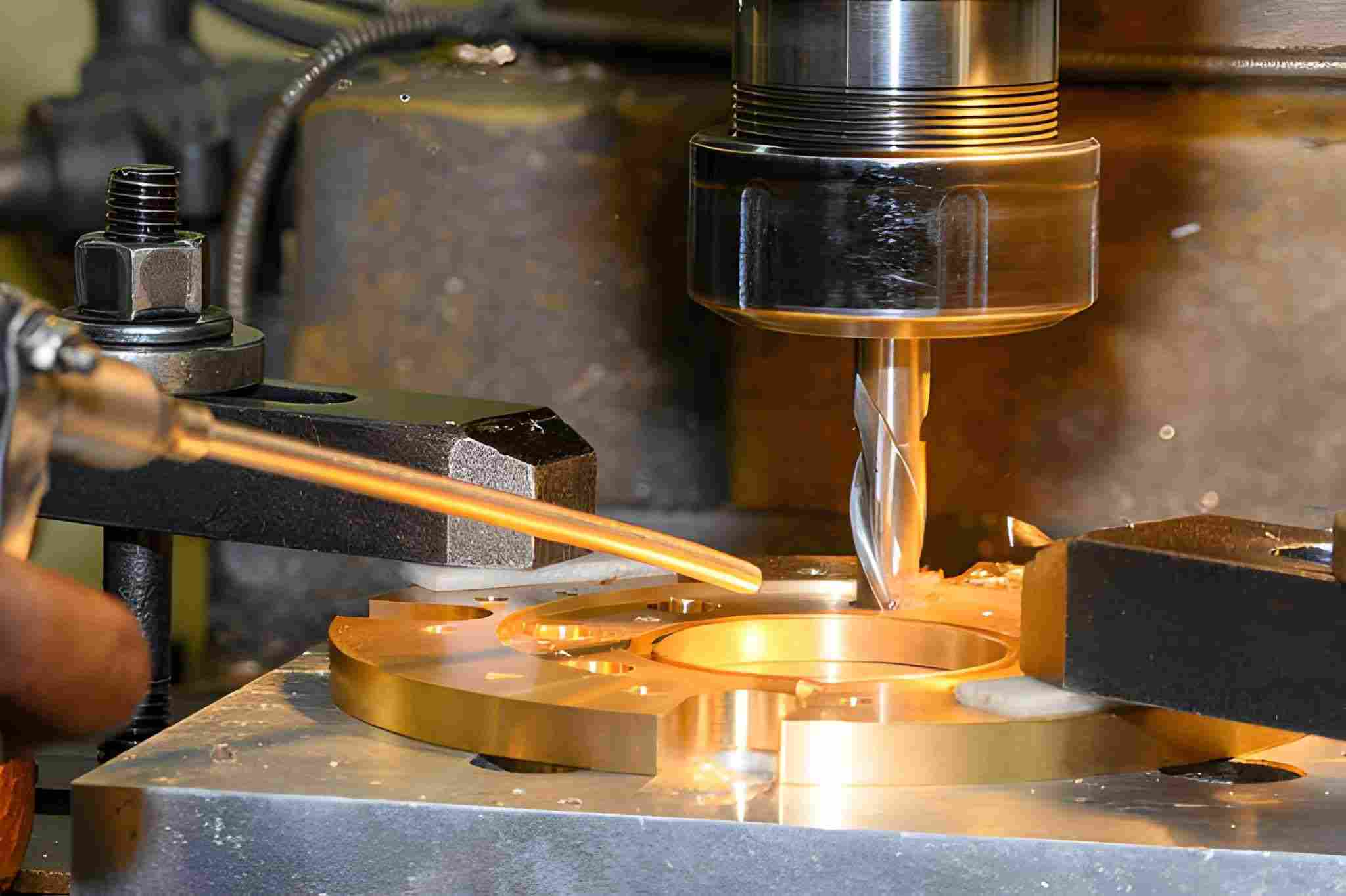
The hole boring process on the NC milling machine by a flat nose end mill tool with a brass ring part. Source: iStock
In CNC machining, boring is used to accurately size and align existing holes after rough machining. It is applied when drilled or cast holes cannot meet the final tolerance or positional requirements. Boring also improves coaxiality between related features, such as bearing seats and shaft bores, making it essential for functional holes in housings, cylinders, and precision assemblies.
Boring vs Drilling vs Reaming
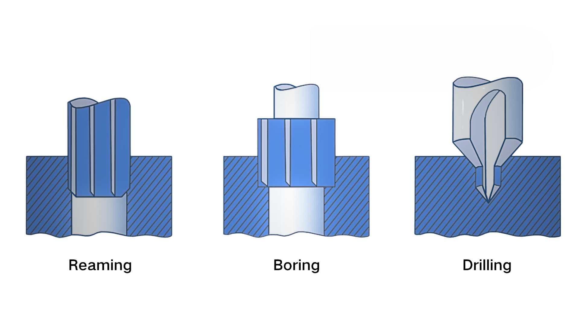
Illustration showing the working mechanism and differences between drilling, boring, and reaming processes in machining. Source: ultirapid.com
| Feature | Drilling | Boring | Reaming |
| Main Purpose | Create an initial hole | Correct size and alignment | Improve size and finish |
| Tool Type | Twist drill | Single-point boring bar | Multi-edge reamer |
| Diameter Control | Low to moderate | High | High (limited adjustment) |
| Position Correction | No | Yes | No |
| Typical Tolerance | ±0.05 - 0.10 mm | ±0.005 - 0.01 mm | ±0.005 - 0.015 mm |
| Geometry Control | Limited | Excellent | Limited |
| Adjustability | Fixed size | Adjustable | Fixed size |
Drilling establishes the initial hole location. Boring corrects size, straightness, and concentricity. Reaming mainly improves size and surface finish when the hole geometry is already close to correct.
Why Boring Matters: Tolerance, Roundness, and Concentricity
Boring is used when a hole must meet tight requirements for size, roundness, and alignmentwith related features.
Boring mainly controls the following critical machining parameters:
● Hole Size (Tolerance): Bore diameter is controlled through tool offsets and fine adjustment, enabling accurate fits for bearings, bushings, and shafts beyond drill size limitations.
● Hole Shape (Roundness and Straightness): Drilled holes may taper or become out of round due to runout and tool deflection. A boring bar cuts along the spindle axis, helping true the hole and remove taper or bell-mouth.
● Hole Alignment (Concentricity and Position): Because boring follows the spindle centerline rather than the original drilled hole, it can help truea hole and improve alignment with mating features and datums—as long as there is enough stock allowance to clean up the bore.
● Internal Surface Quality: Stable boring cuts produce more uniform surfaces with reduced chatter, which is critical for bearing seats, seal grooves, and sliding-fit applications.
Types of CNC Boring Operations
CNC boring is often performed in multiple steps to control size, alignment, and surface quality, especially on critical holes. Each step removes material at a different rate and prepares the hole for the next stage.
Rough Boring
Rough boring is the first boring pass after drilling or casting. Its main job is to remove excess material and straighten the hole enough for later passes.
In rough boring:
● Cutting depth is relatively large
● Feed rate is higher
● Tool rigidity matters more than surface finish
● Minor vibration may be acceptable if it does not compromise straightness and leave enough stock for finishing
Rough boring is used to clean up irregular holes, remove scale, and leave a uniform stock allowance for finishing. Typical applications include cast housings, forged parts, and flame-cut blanks.
Semi-Finish Boring
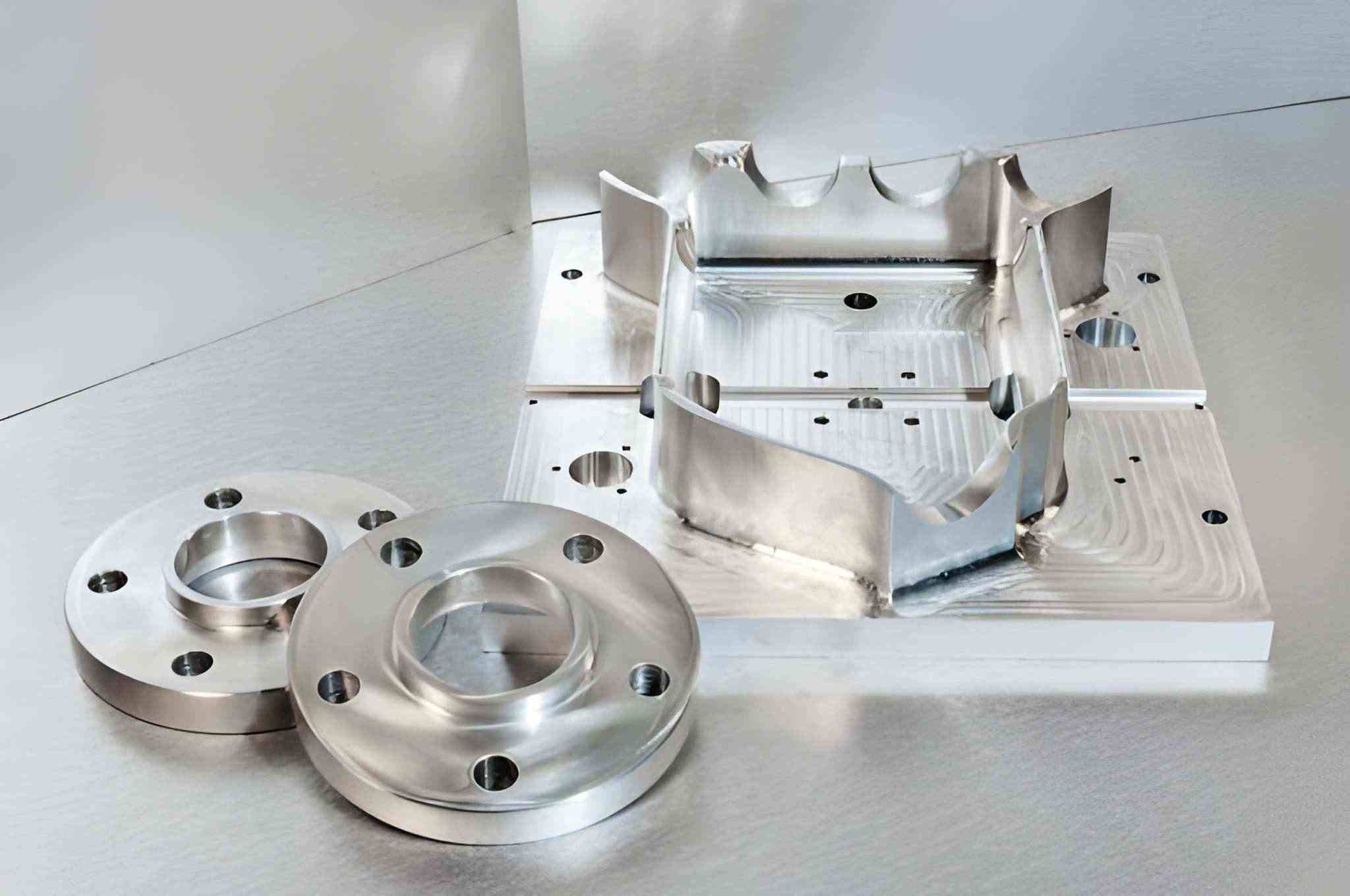
Semi-finished steel blanks and flanges with rough-bored center holes. Source: iStock
Semi-finish boring is used to stabilize the hole before final sizing. This stage improves geometry and prepares the bore for precision cutting.
In this type of boring:
● Stock removal is moderate
● Feed and speed are reduced
● Roundness and straightness are improved
● Tool deflection is minimized
Semi-finish boring is important when tight tolerances are required. It reduces cutting load in the final pass and improves size repeatability. This step is common in gearbox housings, bearing seats, and hydraulic blocks.
Finish/Precision Boring
Finish boring is the final sizing operation. Its purpose is to achieve the required diameter, alignment, and surface quality.
In this stage:
● Cutting depth is very small
● Feed is carefully controlled
● Tool offsets are adjusted precisely
● Vibration must be avoided
Finish boring is used for critical fits such as:
● Bearing bores
● Shaft supports
● Seal housings
● Alignment holes
Instability at this stage can quickly lead to out-of-tolerance size, poor surface finish, or alignment errors—affecting part acceptance and assembly quality.
CNC Boring Operation Comparison
| Machining Stage | Allowance | Accuracy Goal | Typical Use |
| Rough Boring | 0.3 - 1.0 mm per side | Remove casting/forging error and axis deviation | First correction pass on rough holes, castings, and welded parts |
| Semi-Finish Boring | 0.05 - 0.2 mm per side | Control straightness, roundness, and size stability | Bearing seats, hydraulic blocks, gearbox housings |
| Finish / Precision Boring | 0.01 - 0.03 mm per side | Achieve final tolerance, concentricity, and surface finish | Press-fit bores, spindle housings, precision assemblies |
Key Factors Affecting Precision in Boring Machining
In CNC boring, dimensional accuracy is mainly controlled by tool stiffness, spindle condition, and thermal stability. Most bore size and geometry errors can be traced to setup quality, machine condition, and cutting parameter selection.
Tool Selection and Boring Bar Rigidity
Boring bar stiffness directly controls bore straightness and size repeatability.
For standard machining work:
● For a practical starting point:
● Use solid carbide boring bars when the length-to-diameter ratio is around 4:1 or higher.
● Consider damped boring bars when the ratio is around 6:1 or higher.
● Use steel boring bars mainly for shorter overhangs and lighter cuts, especially for finishing.
Bar diameter should be maximized whenever possible. A 20 mm bar is significantly more stable than a 16 mm bar at the same reach.
Insert selection affects cutting force:
● Use positive rake inserts for aluminum and stainless steel
● Use sharp-edge inserts for finishing passes
● Avoid large nose radius inserts in small bores
Tool holding must be rigid:
● Prefer hydraulic or shrink-fit holders for finishing
● Avoid worn ER collets for precision boring
● Clean the spindle taper and holder taper before every setup
Check radial runout at the tool tip with a dial indicator and minimize it before cutting.
Spindle Stability and Machine Alignment
The spindle and axis condition determines roundness and concentricity.
Spindle condition checks:
● Measure spindle runout using a test bar
● Check axial play using a dial indicator
● Monitor vibration during high-speed rotation
Worn spindle bearings can contribute to:
● Oval bores
● Inconsistent surface finish
● Size variation with RPM
Machine alignment practices:
● Check spindle-to-table squareness with a granite square
● Verify linear guide parallelism using laser alignment tools
● Inspect the ball screw backlash and preload condition
For multi-axis boring or interpolation:
● Calibrate rotary axes regularly
● Verify axis positioning accuracy with ballbar tests
● Tune servo parameters to reduce following error
Fixture alignment is equally important:
● Indicate workpiece datum faces
● Ensure the bore axis is aligned with the spindle axis
● Avoid uneven clamping that distorts the part
Cutting Parameters, Material Behavior, and Heat Effects
Cutting conditions must match tool rigidity and material behavior.
Typical boring setup rules:
● Roughing: higher feed, moderate depth
● Finishing: low feed, shallow depth, constant RPM
● Avoid spring cuts without compensation
Feed rate affects both surface finish and size:
● If the feed is too high, tool deflection may increase, leading to taper.
● If the feed is too low, the tool may rub instead of cutting cleanly, which can cause size drift and poor finish.
Material-specific behavior:
Aluminum:
● It expands quickly under extreme heat
● Requires sharp tools and a stable coolant supply
● Size changes during long cycles
Stainless Steel:
● Work-hardens
● Needs consistent feed
● Avoid dwell marks
Titanium:
● Generates heat
● Requires low cutting speed
● Tool expansion affects the diameter
Cast Iron:
● Dimensionally stable
● High tool wear
● Requires frequent tool checks
Thermal control practices:
● Run spindle warm-up programs
● Maintain constant coolant temperature
● Avoid long idle times between rough and finish passes
● Finish critical bores after thermal stabilization
Tool growth should be considered in tight-tolerance work. On high-precision jobs, adjust tool offsets after the machine and part reach thermal stability. For material-specific machining tips, see our CNC machining materials guide.
Best Practices for CNC Boring Operations
Stable boring depends on controlling tool deflection, keeping the cutting process repeatable, and maintaining consistent thermal and mechanical conditions. Most bore quality problems come from excessive overhang, poor offset control, unstable cutting parameters, or inconsistent setups.
Controlling Vibration and Tool Deflection
Vibration and deflection are mainly caused by long tool overhang, low bar stiffness, and unstable cutting forces.
Keep boring bars as short as possible. Set the tool length only to what is required to clear the part. Every extra millimeter of overhang increases deflection risk.
Match bar type to reach:
● Use steel bars only for short bores
● Use solid carbide for medium reach
● Use damped bars for deep holes
Select inserts with low cutting force geometry. Positive rake and sharp edges reduce radial load on the bar and limit bending.
Adjust cutting parameters when chatter appears:
● Reduce the spindle speed first
● Increase feed slightly to stabilize cutting
● Reduce the depth of cut on finishing passes
Use constant surface speed only when the machine and bar are stable. On flexible setups, fixed RPM often produces more consistent results.
Always check the tool clamping torque and holder condition. Loose holders amplify vibration even on rigid machines.
Maintaining Diameter and Roundness Consistency
Consistent bore size depends on stable offsets, predictable tool wear, and controlled thermal behavior. Set tool offsets using trial cuts on scrap or test sections. Do not rely only on nominal insert size.
After rough boring, allow the part to cool before finishing when working with aluminum or thin-walled parts. Thermal expansion during roughing can shift the final size. Use separate tools for rough and finish boring. Finishing with a worn roughing insert causes size drift.
Monitor wear patterns:
● Flank wear causes gradual oversizing
● Built-up edge causes random size shifts
● Chipping causes ovality
Compensate offsets based on measured parts, not estimated tool life. For high-precision bores, always approach the final dimension from the same cutting direction. Avoid alternating climb and conventional passes during finishing.
Check roundness using bore gauges at multiple depths. The size at the entrance, middle, and bottom should match closely. Differences usually indicate deflection or alignment error.
Improving Surface Finish in Precision Boring
Surface finish is controlled by insert condition, feed rate, vibration level, and coolant delivery. Use finishing-grade inserts with polished edges and a small nose radius for tight bores. Large radii increase cutting force and may worsen the finish.
Set finishing feeds carefully:
● Too high will likely cause visible feed marks
● Too low can lead to rubbing and tearing
● Moderate, stable feed gives the best texture
Apply coolant directly to the cutting edge. Poor coolant targeting causes temperature spikes and built-up edge formation.
For deep bores, use through-tool coolant whenever possible. It improves chip evacuation and reduces surface scratching.
Avoid dwelling at the bottom of the bore. Dwelling creates heat spots and circular marks that affect the finish.
Before final passes:
● Replace worn inserts
● Clean chips from the bore
● Verify tool runout
● Reconfirm offsets
For critical finishes, use a light spring pass only after confirming tool stability and measurement method. Spring passes are not a substitute for rigidity and correct offsets, so avoid repeating them unless measurement shows a clear benefit.
Advantages and Typical Applications of Boring Machining
Boring is mainly used when hole size, position, and alignment must be controlled more tightly than drilling or reaming can achieve. It is a correction and finishing process, not a hole-making process.
Why Boring Is Used for Precision Holes
● Allows diameter adjustment through tool offset without changing tools
● Can correct drill runout, tool wander, and off-center holes
● Improves roundness and straightness in deep or long bores
● Maintains concentricity between multiple holes in one setup
● Produces stable press-fit and bearing-fit tolerances
● Works better than reaming on interrupted cuts and cast surfaces
● Reduces dependence on special-size reamers
● Keeps hole geometry consistent across batch production
Typical CNC Boring Applications
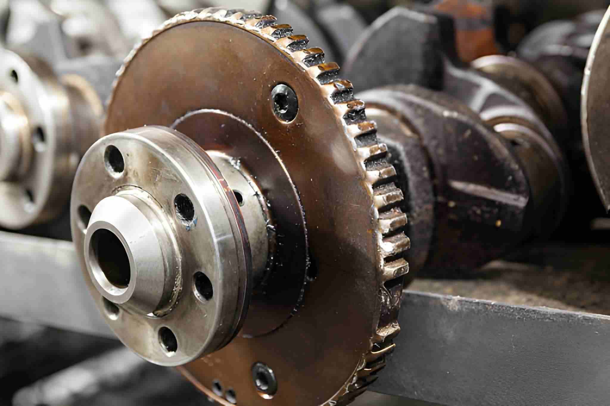
An engine part with a smooth bore and a built-in gear section. Source: iStock
● Bearing seats in housings and gearboxes
● Spindle and shaft mounting bores
● Hydraulic cylinder and piston bores
● Valve blocks and fluid manifolds
● Motor and pump housings
● Engine blocks and transmission cases
● Mold bases and die sets
● Precision fixture and tooling plates
● Alignment bores for dowels and guide pins
● Large-diameter holes beyond reamer capability
When CNC Boring Is Not the Best Choice
Use CNC boring when required hole accuracy, alignment, or geometry cannot be achieved with simpler processes. If tolerances are loose—or if high-volume production favors dedicated tooling—boring may add cost without improving function.
Situations Where Boring Adds Unnecessary Cost
● Hole tolerance is loose and easily met by drilling alone
● Hole is only used for clearance, not alignment or bearing fit
● Surface finish is not function-critical
● The part does not require concentricity with other features
● Large batch production favors faster dedicated tooling
● Hole depth is shallow and stable with standard drills
● Secondary setup is required only for boring
● The tool change and setup time exceeds the quality benefit
Alternatives to CNC Boring
A metal drill bit is making a hole in a steel billet on an industrial drilling machine, with shavings. Source: iStock
● Drilling: Drilling is used when position and size tolerance are moderate, and no correction is required.
● Reaming: It is applied when drilled holes are already straight and only need minor size and finish improvement.
● Interpolated Milling (Helical Boring): Helical milling is used on CNC mills for medium-precision holes without dedicated boring tools.
● Core Drilling & Reaming: These are suitable for production parts with stable cast or forged holes.
● Honing: Honing is selected for ultra-fine surface finish and tight cylindricity in hydraulic and engine components.
● Broaching: Broaching is used when internal profiles or splines are required instead of round bores.

FAQ
What is boring in machining, and why is it needed?
Boring is used to correct and size an existing hole. It is applied when a drilled hole is not straight, not centered, or not accurate enough for bearings, shafts, or press fits.
How to control vibration in CNC boring?
Keep the boring bar as short as possible. Use carbide or damped bars for deep holes. If chatter starts, reduce spindle speed first. Also, make sure the part is clamped securely, and the tool holder is tight.
What tolerance can precision boring achieve?
On a stable CNC machine, boring can hold tight tolerances, but results depend on tooling, setup, and thermal stability. For many production parts, ±0.01 mm is a realistic target. With fine boring heads and good thermal control, tighter tolerances may be achievable.
How is boring different from reaming and drilling?
Drilling makes the hole. Reaming improves the size slightly. Boring is used when the hole must be aligned, round, and located correctly relative to other features.
When is CNC boring not recommended?
Boring is usually unnecessary when drilling already meets the drawing requirements. It is also not suitable for very small holes, high-speed mass production, or simple clearance holes where accuracy is not critical.
Popular Articles
• Cutting with Precision: A Comprehensive Guide to CNC Water Jet Technology
• CNC Coolant Explained: Types, Maintenance & Safety
• Rake Angle in Machining: Machinists’ Guide to Perfect Cuts
• What Steps Are Taken To Minimize Waste In CNC Machining Processes?
• How EDM Wire Cutting Works: Complete Guide to Precision CNC Wire Cutting
Keep Learning
Chatter in Machining: Causes, Effects, and How to Reduce It
CNC milling operation producing visible chatter marks on an aluminum workpiece Quick Chatter Diagnosis Checklist Symptom Most Likely Cause First Action High-pitched squeal Regenerative chatter Change spindle speed ±15% Chatter only in deep pockets Excessive tool overhang Shorten tool Chatter on thin walls Low workpiece rigidity Improve fixturing Chatter after tool replacement Runout / holder issue Check tool holder Chatter only during finishing DOC too small / rubbing Increase feed or adjust speed It ......
What Is Tool Offset in CNC? Types, Setup & Best Practices
CNC tool offset setup with measurement overlay Key Takeaways CNC offsets connect programmed intent with actual cutter position. Length data guides Z-axis depth control. Radius data protects part size during contour milling. Geometry values define the cutter's measured baseline. Wear values support fine correction during production. Verified data lowers scrap risk before full machining. Good offset habits protect tools, fixtures, and parts. In the context of CNC machining , tool offset is the quiet set......
Trochoidal Milling: Complete Guide to High-Efficiency CNC Machining
Key Takeaways Trochoidal milling combines circular cutter motion with continuous forward feed. The cutter normally engages 5 to 20% of its diameter instead of making a full-width cut. A smaller engagement angle limits force changes during slotting and pocket roughing. Low radial engagement often allows greater axial depths of cut than conventional slot milling. CAM software calculates the circular path automatically from the selected machining parameters. This strategy is widely applied to titanium, s......
What Is Die Casting? Process, Materials, and Applications
Key Takeaways Die casting is a metal casting process that forces molten metal into a reusable steel mold under high pressure, producing parts with tight tolerances and good surface finish at high volume. Aluminum die casting is the most common form by far, thanks to its combination of light weight, decent strength, and good corrosion resistance. The die casting process runs through mold preparation, injection, cooling, and ejection in a cycle that can repeat every few seconds to minutes depending on p......
First Angle vs Third Angle: Understanding Orthographic Projection Methods
Key Takeaways Orthographic projection is the system that lets a 3D part be represented through multiple 2D views, front, top, side, and so on. First angle projection and third angle projection are the two standard methods for arranging those views, and they place views in opposite positions relative to the object. First angle projection is the ISO standard used across most of Europe, India, China, Russia, and many other countries following ISO standards Third angle projection is the standard in the Un......
Micro EDM Machining: Capabilities, Materials, and Applications for Precision Components
Key Takeaways About Micro EDM Machining Only electrically conductive materials can be machined. Hole diameters can reach below 50 μm on specialized equipment. The process produces almost no mechanical cutting force, making it suitable for thin or delicate features. Surface integrity still requires attention because recast layers and heat-affected zones may remain after machining. Micro EDM is often combined with CNC machining, with milling producing the main geometry before EDM finishes critical micro......