Thin Wall Machining: CNC Strategies, Deformation Control, and Cost Trade-Offs
15 min
- What Is Thin Wall Machining?
- Thin Wall Thickness: Typical Ranges and What Affects Them
- Why Thin Wall Machining Is Challenging
- Minimum Wall Thickness in CNC Machining
- How Thin-Wall Deformation Occurs During CNC Machining
- Tooling and Cutting Parameters for Thin-Wall CNC Machining
- Workholding Solutions for Thin-Wall Machining
- Cost Drivers in Thin-Wall Machining
- When Thin-Wall Machining Is Not the Best Choice
- Applications of Thin-Wall CNC Machining
- Conclusion: Mastering Thin-Wall CNC Machining for High-Performance Parts
- FAQ
Thin-wall CNC machining is primarily a structural stability problem rather than a simple material-removal problem. When the wall thickness is small relative to its height and unsupported length, the stiffness often drops significantly.
As rigidity decreases, even moderate cutting forces cause elastic deflection. This directly affects dimensional accuracy, flatness, perpendicularity, and part surface finish.
Deformation occurs primarily due to the following three factors:
1. Cutting force
2. Clamping pressure
3. Residual stress redistribution
During machining, radial tool pressure bends the wall away from the cutter. After the tool exits, the material partially springs back, and this results in dimensional error.
In addition, residual stresses in the raw material may redistribute as material is removed. This can cause distortion even without excessive cutting forces. Poor fixturing can further amplify the issue by over-constraining the part and applying uneven loads.
To control deformation, you need a deliberate process strategy. This includes:
● Reducing radial engagement
● Using sharp tools with appropriate rake geometry
● Optimizing step-down and step-over values
● Sequencing roughing and finishing passes to balance stress
● Applying stable workholding that supports thin sections without inducing distortion.
● Toolpath direction, the choice between climb and conventional milling, and thermal management also influence wall stability.
This article explains why thin walls are mechanically unstable in CNC machining. It also covers strategies to control deformation and explains how engineering choices impact cost, consistency, and production efficiency.
What Is Thin Wall Machining?
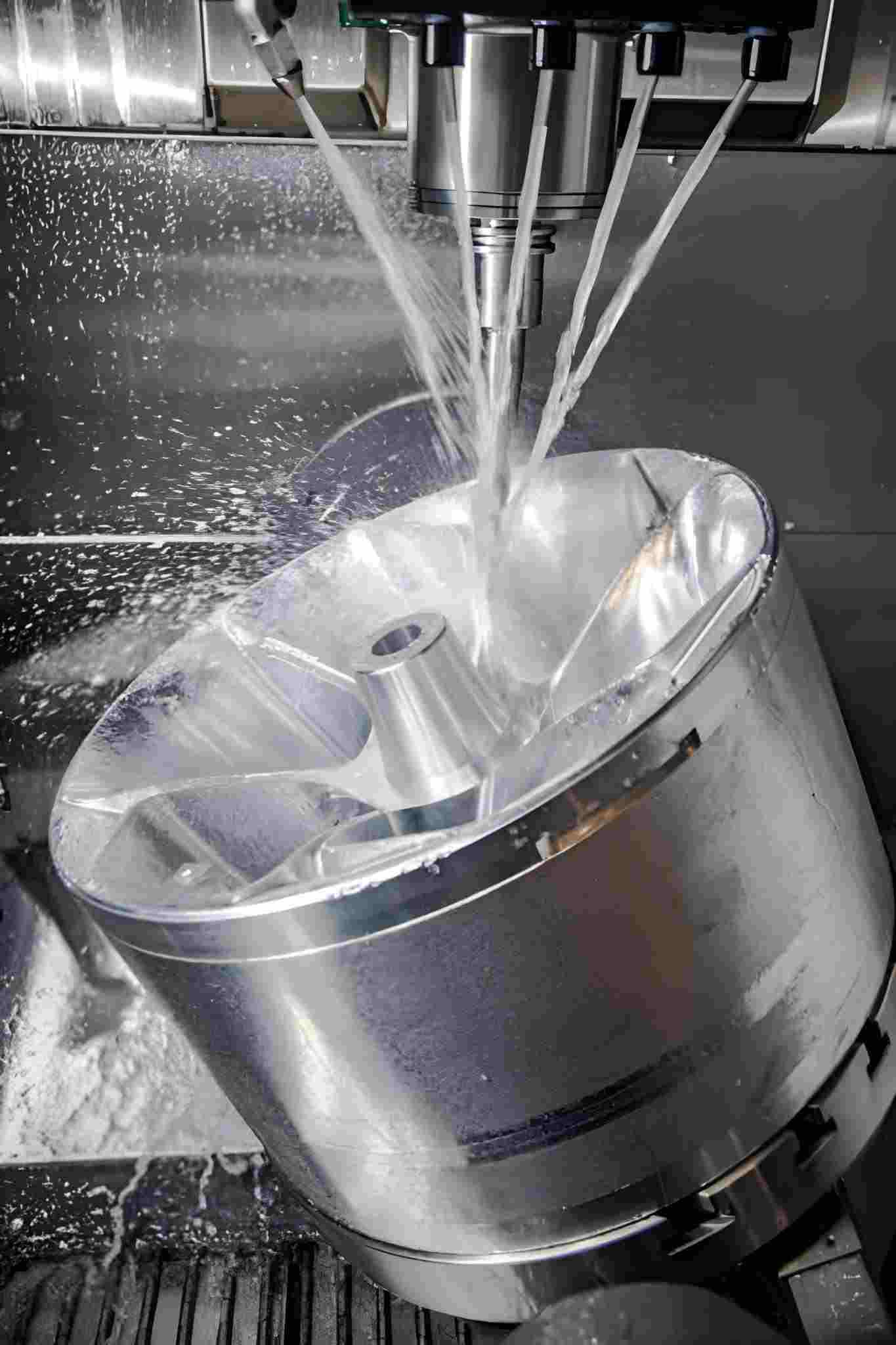
Close-up view of a CNC milling operation cutting thin walls and narrow ribs on a metal part. (Source: iStock)
In CNC manufacturing, a wall is typically considered “thin” when its thickness is small relative to its unsupported height or length.
The actual limits usually depend on the material and geometry. The height-to-thickness ratio is more critical than the absolute thickness. If the ratio is higher, it often leads to reduced stiffness, and machining becomes sensitive to the tool pressure and vibration.
Thin walls are widely used in functional components for the following reasons:
● Weight reduction/saving: Reduction in mass improves energy efficiency, particularly in aerospace, automobile, robotics, and portable devices.
● Better performance-to-weight ratio: The structural integrity is increased when material is deposited only where load paths demand it.
● Space optimization: Intricate designs in electronics, medical devices, and housings often require little wall space to fit the compact assemblies.
● Thermal efficiency: Thin walls are common in housings and thermal designs where geometry and surface area support heat dissipation.
● High-volume parts: Using less material reduces raw stock use. However, it increases machining complexity. Because stiffness drops and process control becomes more critical.
Thin Wall Thickness: Typical Ranges and What Affects Them
These are practical starting ranges, not absolute limits. Final achievable thickness depends on the height-to-thickness ratio, unsupported length, workholding method, and tolerance/surface-finish requirements.
| Material | Thin wall starting point mm | With strong support and conservative cutting mm | Key constraints | Typical failure modes |
| Aluminum | 1.0-2.0 | 0.5-1.0 | Height-to-thickness ratio, tool overhang, radial engagement, chatter stability | Chatter marks, taper, and thickness variation from push-off and spring-back |
| Steel and stainless | 1.5-3.0 | 0.8-1.5 | Cutting forces, tool rigidity, heat, fixture stiffness | Chatter, poor finish, taper or bow, tolerance drift |
| Titanium | 2.0-3.0 | 1.0-2.0 | Heat sensitivity, cutting load, tool wear, need for stable engagement, and strong support | Heat-related distortion, deflection-driven taper, and rapid tool wear |
Why Thin Wall Machining Is Challenging
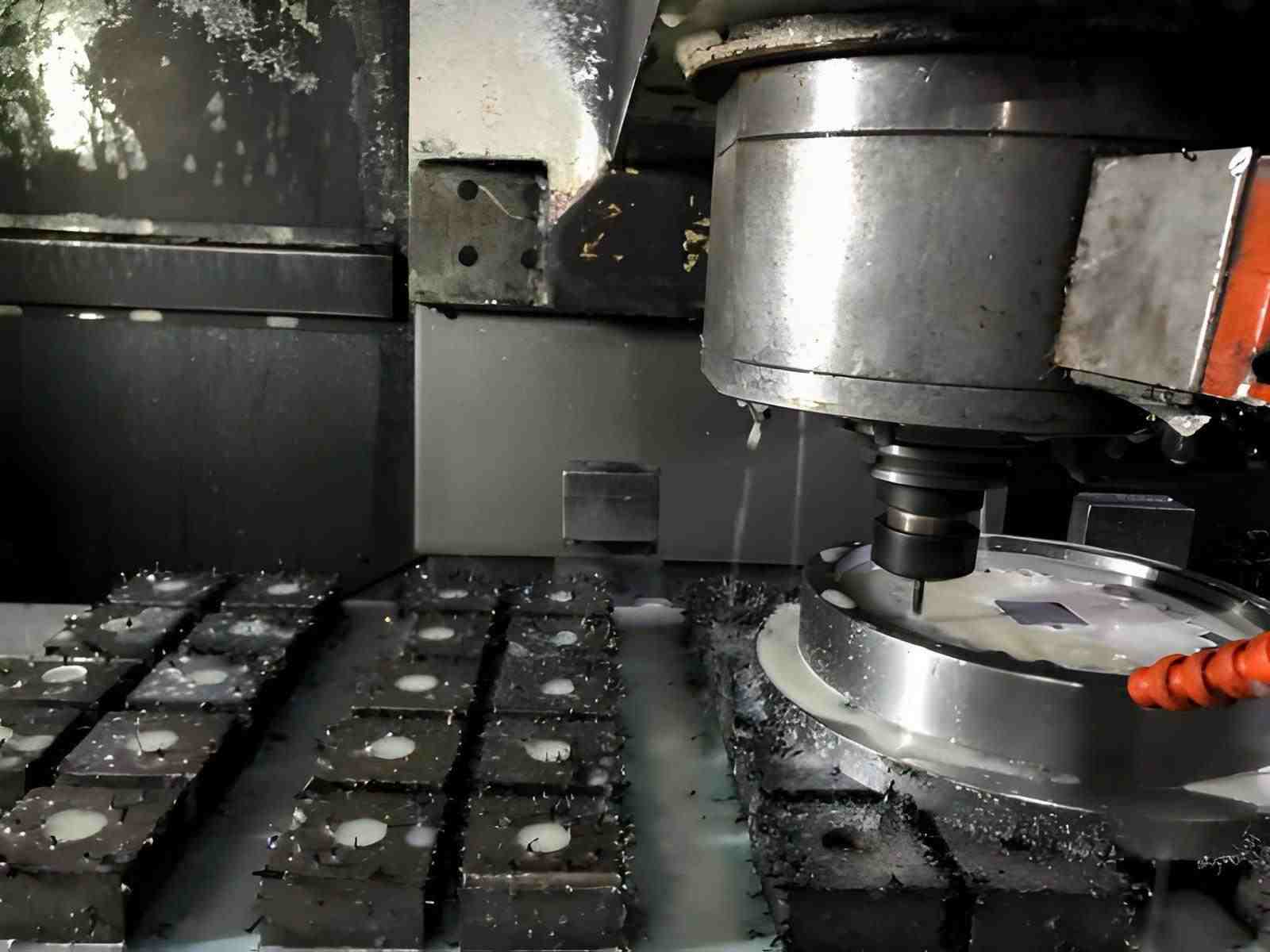
CNC milling machine cutting a metal mold cavity. The rotating tool shapes the inner walls while coolant sprays over the surface. (Source: iStock)
When stiffness drops, the part begins to flex under cutting force. The tool cannot cut cleanly anymore. Instead of removing material, it pushes the wall away. This movement leads to dimensional errors and poor surface finish.
Loss of Rigidity and Structural Stiffness
Bending resistance decreases drastically as wall thickness decreases. A 1 mm wall is not like a miniature 5 mm wall. Instead, it is similar to a moving plate.
Simply put:
● A tall, thin wall acts like a cantilever under side load.
● During milling, the radial cutting force pushes the wall outward.
● After the tool passes, the wall springs back slightly.
This usually results in:
● Final wall thickness variation
● Tapered or bowed surfaces
● Loss of straightness
● Difficulty holding tight tolerances
If internal stresses exist in the raw material, removing stock can also release those stresses and cause the wall to slide even without heavy cutting force.
Sensitivity to Cutting Forces, Heat, and Vibration
Thin sections are highly sensitive to process conditions. For example:
Cutting Forces
● Higher radial engagement increases lateral deflection.
● Aggressive step-down increases bending stress.
● Tool wear increases cutting pressure and instability.
Heat
● Thin walls have low thermal mass.
● Localized heat causes expansion during the machining operation.
● As the part cools, a dimensional shift can occur.
To minimize thermal effects, specialized cutting fluids or cooling techniques, such as through-tool coolant or air-blast cooling, can be employed to control heat buildup and prevent distortion.
Vibration
● Reduced stiffness lowers the natural frequency.
● The wall is more prone to chatter.
● Chatter increases surface roughness and dimensional error.
In rigid parts, these effects are relatively minor. In thin-wall components, they directly determine whether the part meets tolerance or becomes scrap.
One of the biggest challenges in thin-wall machining is determining the minimum wall thickness achievable for different materials. The following table outlines general guidelines based on material type and machining conditions.
Minimum Wall Thickness in CNC Machining
To achieve reliable machining of thin walls, there are general guidelines regarding the minimum achievable thickness, which depend on several factors, including material type, height-to-thickness ratio, tooling, and fixturing. Here’s an overview of the typical ranges for various materials and the practical constraints that may affect them.
| Material | Starting Thin Wall Thickness (mm) | Achievable Thickness (mm) | Key Constraints | Typical Failure Modes |
| Aluminum | 1.0-2.0 | 0.5-1.0 | Height-to-thickness ratio, tool overhang, radial engagement, chatter stability | Chatter marks, taper, thickness variation from push-off and spring-back |
| Steel & Stainless | 1.5-3.0 | 0.8-1.5 | Cutting forces, tool rigidity, heat, fixture stiffness | Chatter, poor finish, taper or bow, tolerance drift |
| Titanium | 2.0-3.0 | 1.0-2.0 | Heat sensitivity, cutting load, tool wear, need for stable engagement and strong support | Heat-related distortion, deflection-driven taper, rapid tool wear |
Notes on Thin-Wall CNC Machining
● Thin-wall CNC machining usually requires shallow depths of cut and multiple passes. Otherwise, vibration can cause wall deformation or even cracking, which increases machining difficulty and cycle time.
● Rule-of-thumb minimum wall thickness:
○ Metals: ≥ 0.8 mm (down to ~0.5 mm in favorable conditions)
○ Plastics: ≥ 1.5 mm (down to ~1.0 mm in favorable conditions)
● Actual achievable wall thickness depends on material, wall height, geometry, tooling, fixturing, and tolerance requirements.
How Thin-Wall Deformation Occurs During CNC Machining
Thin-wall deformation occurs because the remaining section cannot carry machining loads without bending. As material is removed, stiffness drops. The cutting tool, internal material stress, and clamping forces then become large relative to the wall’s bending resistance.
The deformation mechanisms are predictable and typically fall into three categories.
Cutting-Force-Induced Deflection
In milling operations, the cutter generates tangential force (material removal) and radial force (side load). For thin walls, the radial component is the main concern.
Tool Engagement Direction and Force Vectors
● Radial step-over directly increases lateral load on the wall.
● Greater axial depth increases the bending moment along the wall height.
● Greater unsupported wall height increases deflection.
● Long tool overhang increases dynamic loads and instability.
When the cutter engages a tall, thin wall, the wall deflects away from the tool.
Toolpath-Induced Wall Bending
● Machining from one side only creates directional bending.
● Slotting produces a constant high radial load.
● Deep axial cuts on thin features increase wall taper risk.
In general, symmetrical material removal and light finishing passes minimize cumulative bending error.
Material Stress Release During Machining
Rolled and extruded material stock contains residual stress from forming and cooling processes. These stresses remain balanced until material is removed.
Residual Stress Redistribution
● Removing stock from one face first disturbs the internal stress balance.
● Deep-pocket roughing can cause visible bowing.
● The thinner the remaining section, the less resistance to stress-driven movement.
Deformation After Material Removal
● Parts may distort after roughing, even without aggressive parameters.
● Geometry may change between roughing and finishing operations.
● Warping frequently becomes apparent only after unclamping.
Workholding-Induced Distortion
Thin walls are sensitive to clamping because they lack structural stiffness.
Over-Clamping and Localized Compression
● High clamp force compresses thin sections elastically.
● Point clamps introduce localized bending.
● Insufficient support beneath thin floors allows downward deflection during cutting.
Elastic Recovery After Unclamping
● When clamps are released, compressed areas recover.
● Flatness and perpendicularity errors appear after removal.
● Parts measure within tolerance while fixtured, but shift afterward.
Tooling and Cutting Parameters for Thin-Wall CNC Machining
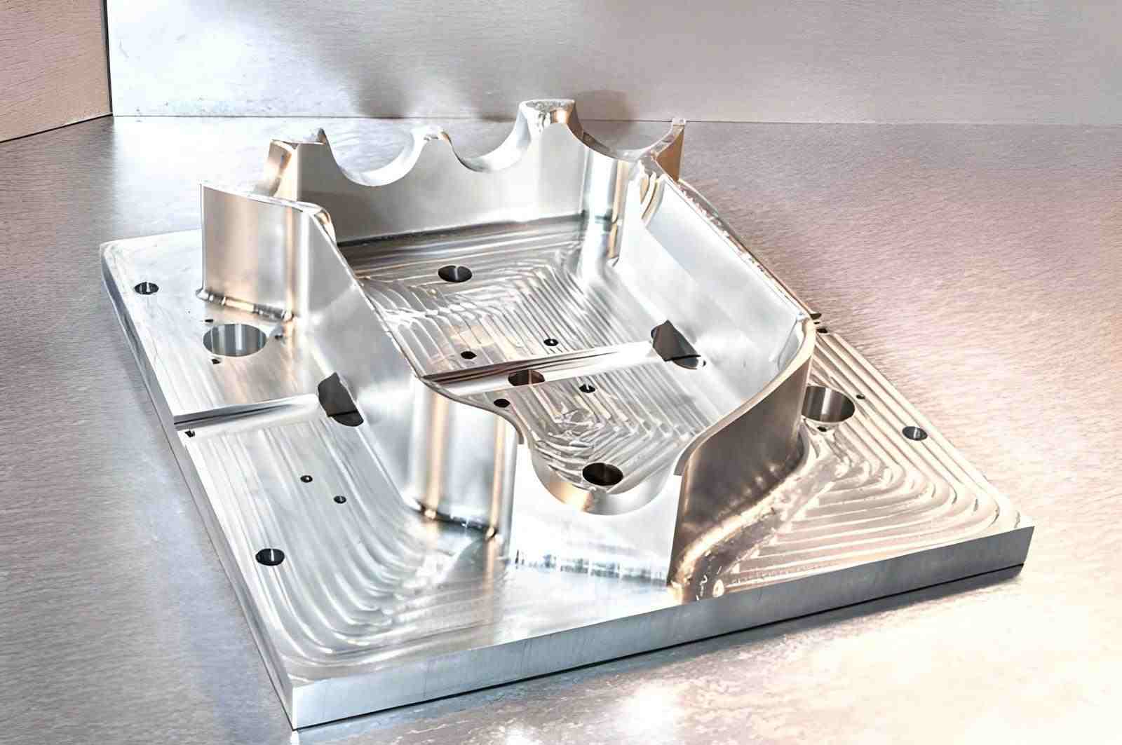
Fully machined metal mold displayed in a workshop. The mold shows finished walls, cavities, and thin sections with smooth surfaces. (Source: iStock)
Machining thin walls is challenging if the part itself is flexible. You must carefully decide on tools and cutting parameters to prevent deflection, vibration, and poor surface finish while keeping tolerances tight.
Tool Geometry, Engagement, and Chatter Control
Thin walls are prone to bending and vibration under cutting forces. Here are practical strategies to reduce deflection and vibration:
● Use Short, Rigid Tools: Long tools create leverage that tends to incur deflection. While short, stiff tools reduce bending and improve stability.
● Minimize Tool Overhang: The longer the tool extends from the spindle, the more likely it is to chatter and bend during cuts.
● Reduce Radial Engagement: Engage only part of the tool diameter at once. This helps reduce side forces on thin walls.
● Sharp Tools and Polished Flutes: Sharp edges cut cleanly, and polished flutes prevent chips from clogging and causing vibration.
● Climb Milling for Thin Sections: Climb milling reduces the loading on the thin wall, and often helps reduce rubbing and improve finish.
Workholding Solutions for Thin-Wall Machining
In thin-wall machining, workholding directly affects dimensional accuracy. You must restrain the part against cutting forces while keeping it as stress-free as possible.
Effective fixturing focuses on uniform support, controlled clamping force, and the minimization of localized stress.
Supporting Thin Walls Without Over-Clamping
● Thin features should be supported as close as possible to the cutting zone.
● Unsupported height increases bending under radial load.
Practical approaches include:
● Support Near the Machining Area: Place backing support beneath thin floors or walls being cut. This will help minimize deflection under tool pressure.
● Distribute Clamping Force: Use wider contact areas instead of point clamps. Spreading the load reduces localized compression.
● Use Minimum Effective Clamp Force: Apply only enough force to resist cutting loads. Excessive force elastically deforms thin sections even before machining begins.
● Avoid Cantilever Setups When Possible: If one side of a wall is unsupported, reposition or flip the part to maintain balanced support.
● Machine in Stages: Keep material around thin sections during roughing. Remove the final support stock only during finishing.
Soft Jaws, Vacuum Fixtures, and Custom Supports
Standard vise setups are often unsuitable for thin-wall components. Alternative fixturing methods improve support and reduce distortion.
Soft Jaws
● Machined to match part geometry for full-surface contact.
● Reduce localized stress compared to hard jaws.
● Improve repeatability in production runs.
Vacuum Fixtures
● Provide a uniform holding force across a large surface area.
● Eliminate high localized clamp pressure.
● Effective for thin plates and shallow-walled parts.
● Require sufficient surface area and good sealing to maintain holding force.
Custom Supports and Backing Plates
● Sacrificial material is left beneath thin areas during machining.
● Custom nests to support complex geometry.
● Temporary ribs or tabs that are removed in a final operation.
Balancing Feed Rate, Depth of Cut, and Surface Finish
A batch of shiny metal aerospace parts after CNC machining, neatly arranged on a factory floor. (Source: iStock)
Cutting parameters must be carefully optimized for thin features:
● Feed rate: Moderate or low feeds should be used in order to put less pressure on the thin wall.
● Depth of cut: Shallow cuts are safer for thin sections, especially on finishing passes. Roughing can remove bulk material first while keeping the walls thicker.
● Step-over and toolpath direction: Smaller stepovers reduce lateral pressure and prevent wall deflection.
● Light finishing passes: Multiple shallow passes maintain dimensional control and improve surface quality without stressing the wall.
● Spindle speed: Avoid speeds that resonate with the wall’s natural frequency.
Cost Drivers in Thin-Wall Machining
Thin-wall parts are inherently more expensive to produce than standard-thickness components. It’s important to understand the main cost drivers to help make design and process decisions that balance performance and the intended budget.
Why Thin-Wall Parts Cost More to Machine
● Material Waste and Scrap Risk: Thin walls deform easily during cutting. Thus, parts may fail inspection and require rework, increasing scrap rates.
● Specialized Tooling: Short, rigid, and often custom tools are needed to avoid deflection and chatter. This increases tooling cost.
● Slower Machining Speeds: Feed rates and depths of cut must be reduced to protect fragile features. This often increases cycle time.
● Tighter Tolerances: Thin-wall features often demand precise dimensional control and require additional finishing passes with meticulous in-process inspection.
● Complex Fixturing: Custom soft jaws, supports, or vacuum fixtures are required to hold parts securely to avoid distortion.
Design and Process Choices That Reduce Cost
● Increase Wall Thickness Where Possible: Even minor improvements increase rigidity and permit quick machining.
● Keep your design simple: No deep pockets, undercuts, or long unsupported walls to make it easy to set up.
● Optimize Tool Paths: Step-down roughing and repeated light finishing passes minimize stress on the walls and increase tool life.
● Select Machinable Materials: Choose alloys with higher stiffness or slightly lower ductility to reduce deformation and tool wear.
● Plan Efficient Workholding: Use soft jaws, vacuum fixtures, or a dedicated jig to simplify setups.
● Consolidate Parts: You can save on the setups and machining time by reducing the number of thin-wall parts that are individual.
When Thin-Wall Machining Is Not the Best Choice
Thin-wall CNC machining isn’t always the right choice. Sometimes, reducing weight or saving space can increase cost, add complexity, and risk part deformation. In such instances, exploring alternative design methods is a better approach.
Alternatives to Thin-Wall Design
● Thicken the wall slightly: Slightly thicker walls improve rigidity and machinability.
● Use Inserts or Hybrid Designs: To keep the strength, combine thicker support ribs or metal inserts with thin sections.
● Eliminate Multiple Parts: Re-design assemblies with fewer parts.
Tradeoff Performance/Manufacturability/Cost
● Comparing Function vs. Cost: Question whether the thin wall is important in weight reduction, or can a slightly thicker wall work.
● Adjust Tolerances: Tighter tolerances in design lead to an increase in machining time and scrap.
● Use appropriate materials: Choose stiffer alloys to limit part deformation and tool wear.
Applications of Thin-Wall CNC Machining
Thin-wall CNC machining is ideal when you need parts that are light, strong, and precise. It removes extra material while keeping the part stable and accurate.
Structural and load-bearing components
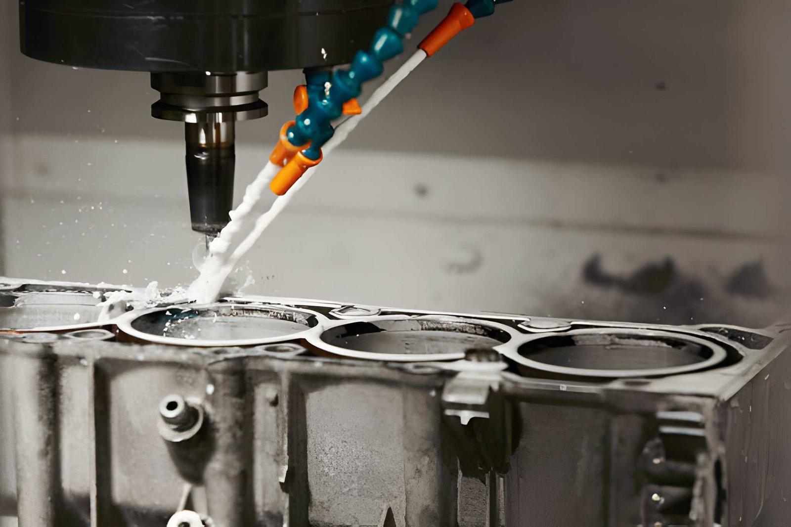
High-precision CNC milling machine drilling holes in a car engine block. (Source: iStock)
Thin walls are common in brackets, frames, and supports. These parts must handle high stress without bending or breaking. In aerospace, automotive, and robotics, lighter parts improve performance and efficiency.
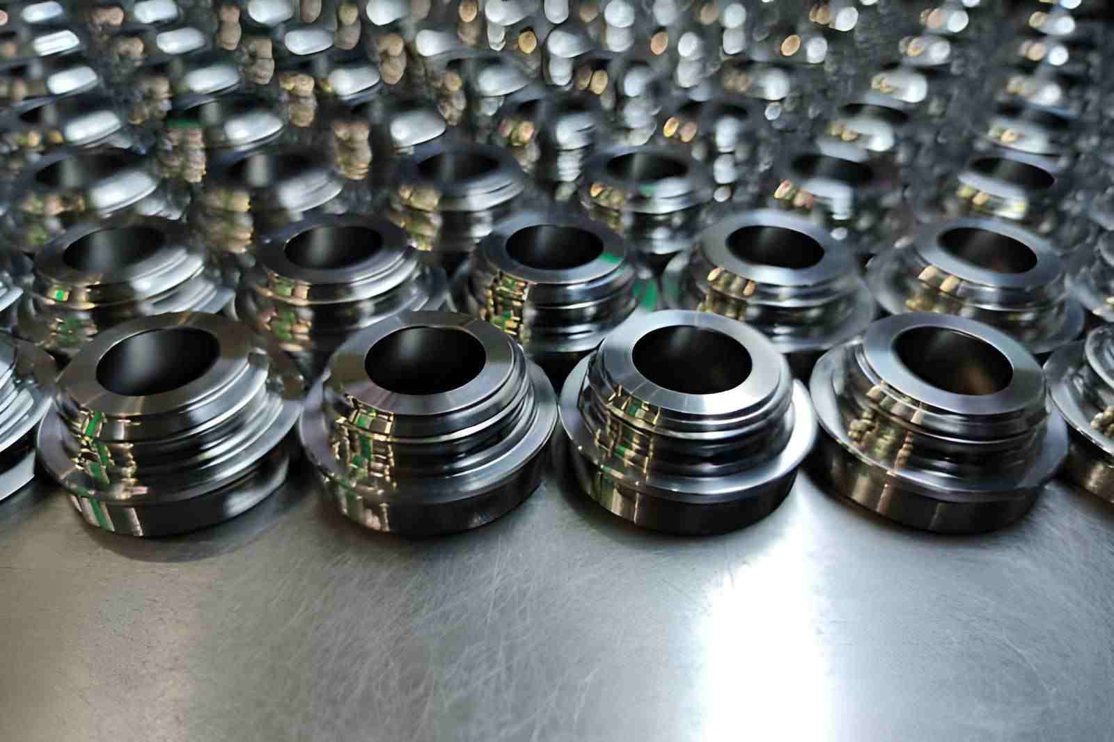
Precision Housings, Enclosures, and Electronic Casings
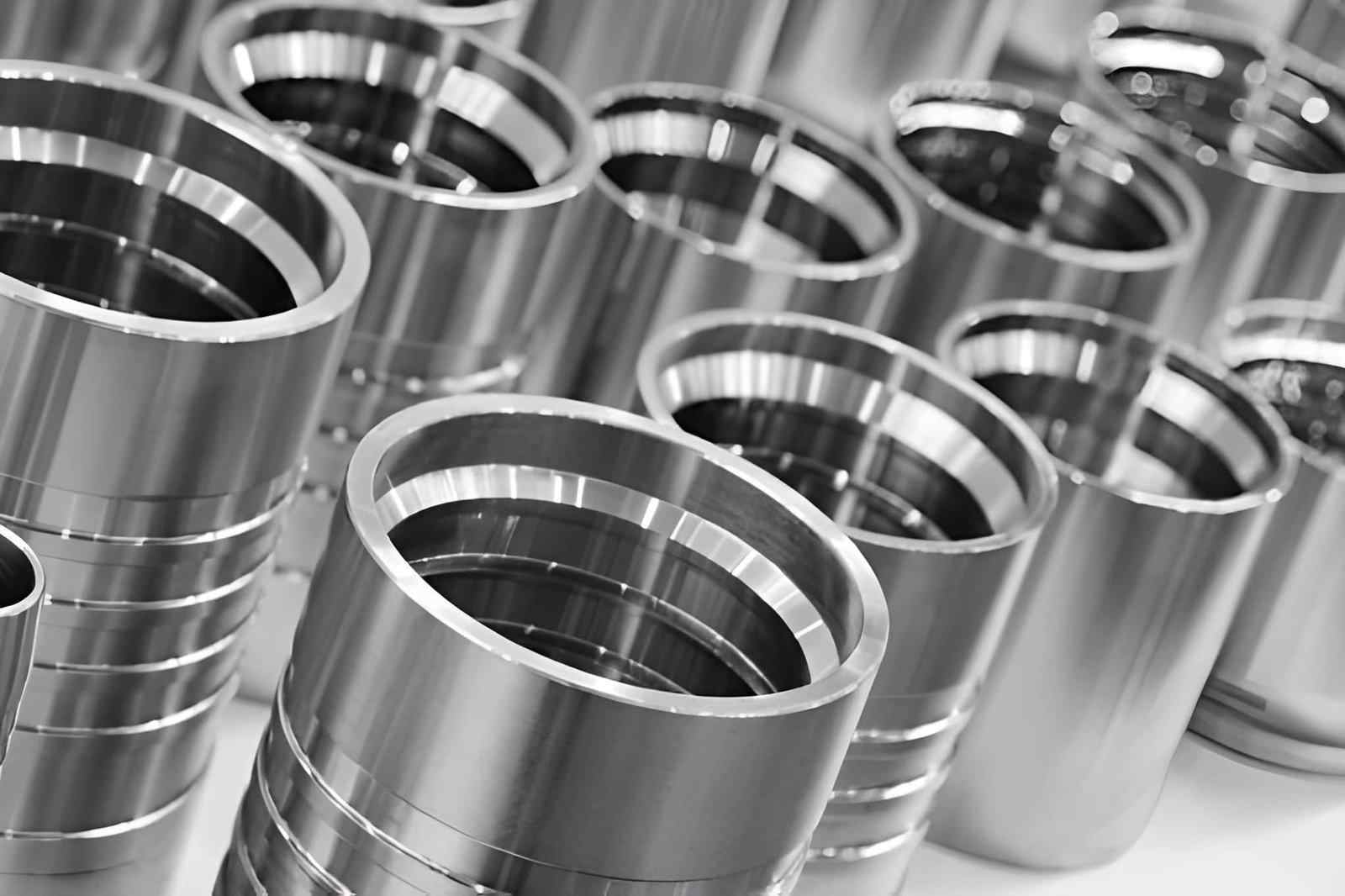
Rows of metal cylinders standing upright on a metalworking shop floor. (Source: iStock)
Thin walls are also used in electronic housings and machine enclosures. They ensure consistent wall thickness, proper fit, and alignment while helping manage heat, all without adding unnecessary weight.
Conclusion: Mastering Thin-Wall CNC Machining for High-Performance Parts
Successfully machining thin-wall components requires careful attention to material, tooling, fixturing, and cutting parameters. By following best practices, selecting the right tools, and optimizing workholding, you can reduce deformation and improve accuracy in your parts. Contact JLCCNC today for consultation on your thin-wall CNC projects and get fast, precision machining solutions.

FAQ
What is considered a thin wall in CNC machining?
A thin wall is a section of a part with a small thickness relative to its height or length. It is usually prone to bending or vibration during CNC machining. Exact thickness depends on material and part geometry.
How thin can CNC machining reliably achieve?
The minimum wall thickness depends on material stiffness, height, and machine capability. In practice, walls below 1–2 mm often need special support or tooling to machine accurately.
Is thin-wall machining suitable for production parts or only prototypes?
Thin-wall machining can be used for both prototypes and production parts, but production requires careful fixture design, consistent setups, and possibly specialized tooling to maintain repeatability.
How do you prevent deformation when machining thin-wall parts?
● Support the wall as much as possible
● Use soft jaws, pads, or custom fixtures
● Apply clamping evenly, avoid point loads
● Keep cutting forces low to reduce deflection
Why is thin-wall machining more expensive?
Thin-wall parts require careful fixturing, slower feeds, and lighter cuts to prevent distortion. This increases setup time and machining time, which raises costs.
How can the cost of thin-wall CNC machining be optimized?
To optimize costs, consider increasing wall thickness slightly to improve rigidity, simplifying part design, optimizing tool paths to reduce machining time, using efficient fixturing, and consolidating parts to reduce setups.
Popular Articles
• Cutting with Precision: A Comprehensive Guide to CNC Water Jet Technology
• CNC Coolant Explained: Types, Maintenance & Safety
• Rake Angle in Machining: Machinists’ Guide to Perfect Cuts
• What Steps Are Taken To Minimize Waste In CNC Machining Processes?
• How EDM Wire Cutting Works: Complete Guide to Precision CNC Wire Cutting
Keep Learning
Trochoidal Milling: Complete Guide to High-Efficiency CNC Machining
Key Takeaways Trochoidal milling combines circular cutter motion with continuous forward feed. The cutter normally engages 5 to 20% of its diameter instead of making a full-width cut. A smaller engagement angle limits force changes during slotting and pocket roughing. Low radial engagement often allows greater axial depths of cut than conventional slot milling. CAM software calculates the circular path automatically from the selected machining parameters. This strategy is widely applied to titanium, s......
What Is Die Casting? Process, Materials, and Applications
Key Takeaways Die casting is a metal casting process that forces molten metal into a reusable steel mold under high pressure, producing parts with tight tolerances and good surface finish at high volume. Aluminum die casting is the most common form by far, thanks to its combination of light weight, decent strength, and good corrosion resistance. The die casting process runs through mold preparation, injection, cooling, and ejection in a cycle that can repeat every few seconds to minutes depending on p......
First Angle vs Third Angle: Understanding Orthographic Projection Methods
Key Takeaways Orthographic projection is the system that lets a 3D part be represented through multiple 2D views, front, top, side, and so on. First angle projection and third angle projection are the two standard methods for arranging those views, and they place views in opposite positions relative to the object. First angle projection is the ISO standard used across most of Europe, India, China, Russia, and many other countries following ISO standards Third angle projection is the standard in the Un......
Micro EDM Machining: Capabilities, Materials, and Applications for Precision Components
Key Takeaways About Micro EDM Machining Only electrically conductive materials can be machined. Hole diameters can reach below 50 μm on specialized equipment. The process produces almost no mechanical cutting force, making it suitable for thin or delicate features. Surface integrity still requires attention because recast layers and heat-affected zones may remain after machining. Micro EDM is often combined with CNC machining, with milling producing the main geometry before EDM finishes critical micro......
Bearings: Types, Applications, Materials, and Selection Guide
Bearings are small components, but they play a critical role in the reliability of mechanical systems. The wrong bearing selection can lead to excessive friction, vibration, premature wear, and unexpected equipment downtime. In this guide, I'll break down every common type of bearing, what they're used for, and how to choose the right one for your project. Whether you're a mechanical engineer, a hobbyist, or just someone trying to understand how things work, this guide has you covered. What Are Bearin......
CNC Cutting Fluid: Types, Functions, Applications, and Selection Guide
Key Takeaways Cutting fluid in machining performs four functions simultaneously: cooling the tool and workpiece, lubricating the tool-chip interface to reduce friction, carrying chips away from the cut zone, and protecting machined surfaces from corrosion between operations. Different machining operations need different fluid priorities: high-speed aluminum milling may need adhesion control and chip evacuation, threading and tapping need strong lubrication, and grinding requires both cooling and fine ......