Fillet in CNC Machining: How to Choose Radii, Reduce Cost, and Compare Chamfers
14 min
- What Is a Fillet in CNC Machining?
- Internal vs External Fillets in CNC-Machined Parts
- Chamfer vs Fillet: Key Differences
- How Fillets Are Machined in CNC Processes
- Fillet Design Guidelines for CNC-Machined Parts
- When to Use Fillets in CNC Machining
- Fillet Cost Considerations in CNC Machining
- High-Precision CNC Fillet Machining at JLCCNC
- Conclusion
- FAQ
Fillets are functional features in CNC machining—not decorative ones. Their radius and placement affect tool selection, cycle time, and part strength, especially in internal corners where cutting tools limit what can be produced. This guide explains what fillets are, how they’re machined, how they compare with chamfers, and how to choose radii that balance performance and cost.
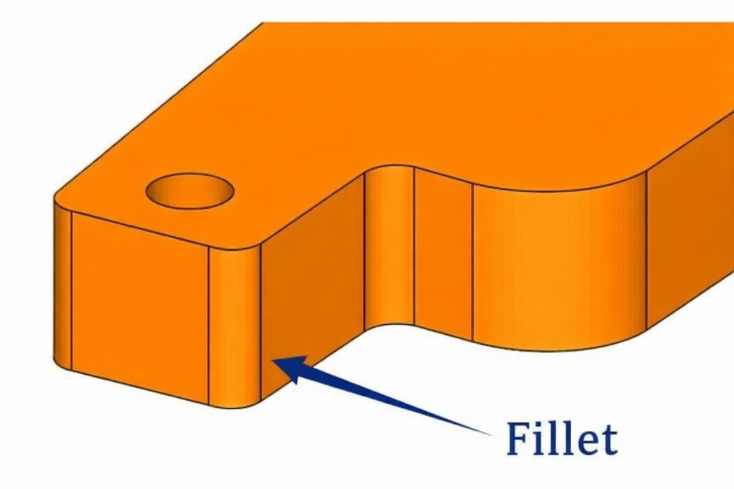
Fillet in CNC Machining [image source: https://www.shutterstock.com/ AI Edited]
What Is a Fillet in CNC Machining?
In engineering design, a fillet is a rounded transition between two surfaces or edges, defined by a radius R (for example, R2 mm or R0.125 in).
Fillets are used to:
● Reduce stress concentration at corners (improving fatigue performance)
● Improve manufacturability, especially in internal corners limited by end mill geometry
● Create smoother transitions for a better fit, contact, or flow
Internal vs External Fillets in CNC-Machined Parts
Internal and external fillets are designed for different reasons in CNC machining. Internal fillets are mainly limited by cutting tools, while external fillets are usually easier to machine. Understanding this difference helps designers choose radii that meet performance needs without driving unnecessary cost.
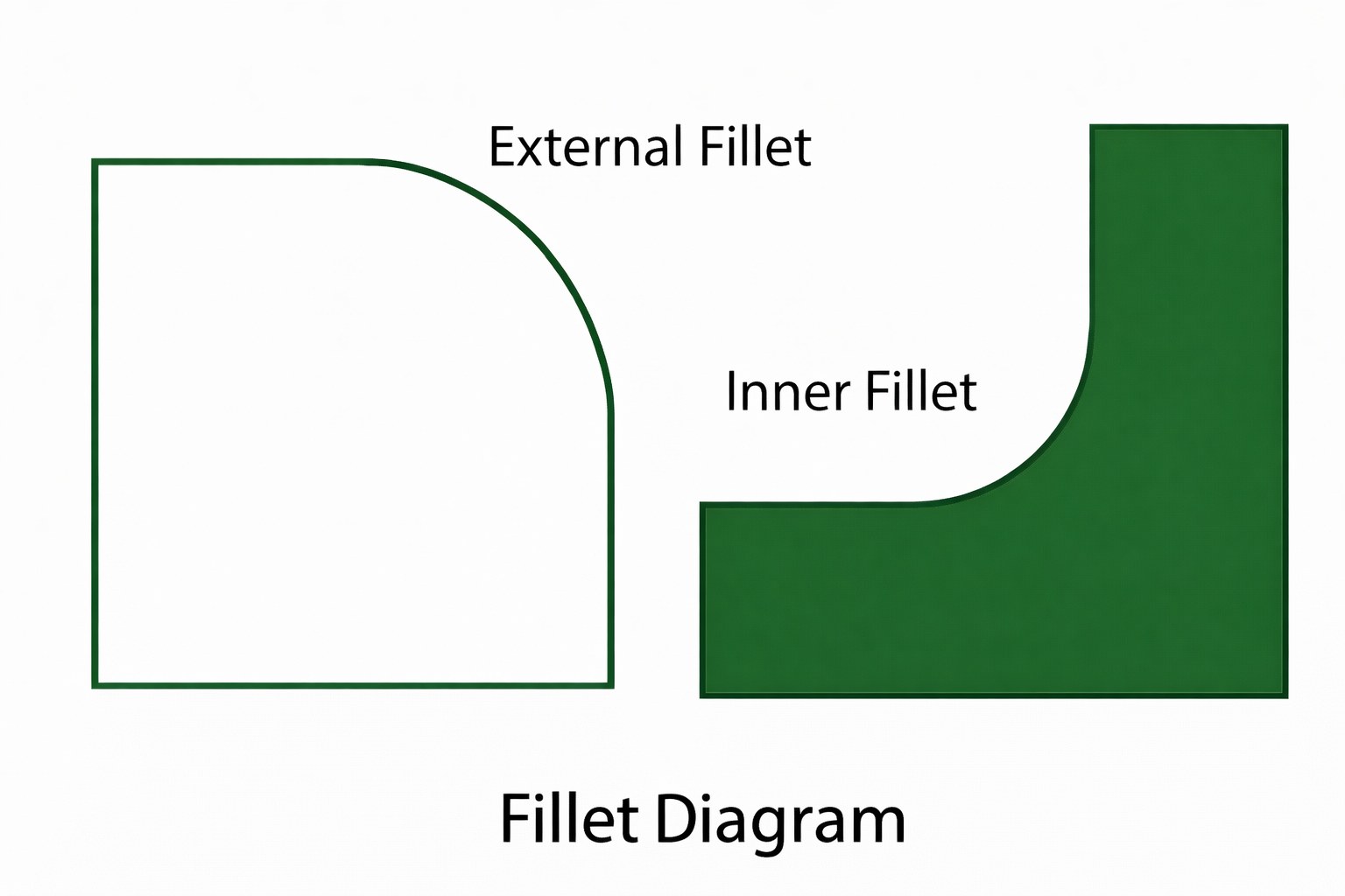
Internal vs External Fillets in CNC Parts [image source: https://www.shutterstock.com/ AI Edited]
Internal Fillets: Tooling Constraints and Cost Impact
CNC machining is most sensitive to internal fillet design, as internal fillets are directly constrained by cutting tool geometry. The practical minimum fillet radius CNC is therefore governed by tool diameter, tool reach, and pocket depth, rather than CAD preference. In practice, the internal corner fillet radius is set by end mill diameter, tool reach, and pocket depth rather than CAD preference.
Internal fillets commonly appear in pockets, slots, and cavities because milling tools are round and can’t produce perfectly sharp inside corners. For typical milled features, the In practice, minimum internal fillet radius also depends on pocket depth, tool reach, and rigidity (length-to-diameter ratio).
Smaller internal fillets often increase cost because they require smaller tools, which typically:
1. Run at slower feeds and increase cycle time
2. Are less rigid, making deflection and surface finish issues more likely
3. Wear faster (and can break more easily), increasing tooling risk and replacements
For example, specifying a 0.5 mm internal fillet may require a micro end mill. Smaller tools typically increase cycle time (slower feeds and lighter cuts) and raise the risk of tool breakage, especially in hard materials or deep pockets.
External Fillets: Use Cases and Design Benefits
External fillets are applied to outside edges and corners and are usually less constrained by tool geometry. They are commonly used to:
● Improve edge durability and reduce chipping on exposed corners
● Remove sharp edges for safer handling
● Improve aesthetics with smoother transitions
● Reduce snagging and minor interference during assembly
External fillets can often be machined with larger, more rigid cutters, so they’re typically faster and less expensive than tight internal fillets. They’re usually added for durability, safety, ergonomics, or appearance, not because the process demands them.
The key differences between internal and external fillets are summarized below:
| Aspect | Internal Fillets | External Fillets |
| Location | Inside corners of pockets, slots, and cavities | Outside edges and corners of a part |
| Primary Purpose | Enable tool access and manufacturability | Improve strength, safety, and aesthetics |
| Tooling Limitation | Strictly limited by end mill diameter | Minimal tooling limitations |
| Design Driver | Cutting tool geometry | Functional, ergonomic, or visual needs |
| Typical Radius Size | Larger radii are preferred to allow standard tools | Can be small or large as needed |
| Machining Impact | Small radii increase cycle time and cost | Generally faster and easier to machine |
| Cost Sensitivity | High—tight radii significantly raise the cost | A lower radius size has less of a cost impact |
| Common Applications | Pocket corners, ribs, internal transitions | Housing edges, flanges, exposed corners |
Common Places Fillets Appear in CNC-Machined Parts
Fillets are common in CNC-machined parts, especially in:
● Pocket and slot corners (driven by end mill geometry)
● Rib-to-wall and boss-to-wall transitions (reduce stress concentration and improve load transfer)
● Flange and housing transitions (strength and smoother geometry changes)
● Mounting features and load-bearing corners (fatigue and durability improvements)
Because CNC cutting tools are round, fillets are often unavoidable—especially in internal corners. Designers should plan fillet radii early, since the right radii improve manufacturability, strength, and cost efficiency.
Chamfer vs Fillet: Key Differences
Both chamfers and fillets modify edges, but they solve different problems. Use fillets for stress reduction and smooth transitions; use chamfers for quick edge breaks, lead-ins, and lower machining complexity.
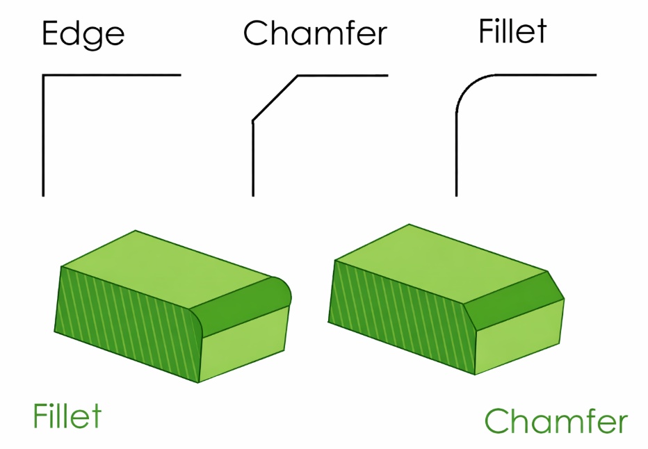
Chamfer vs Fillet [image source: https://www.shutterstock.com/ AI Edited]
Geometric Differences Between Chamfers and Fillets
A fillet is a rounded edge or corner defined by a radius.
A chamfer is a flat, angled edge break defined by an angle and a size (for example, 1 mm × 45°).
| Feature | Fillet | Chamfer |
| Geometry | Curved radius | Flat angled face |
| Stress distribution | Excellent | Moderate |
| Tooling | Radius-limited | Simple |
| Machining speed | Slower for small radii | Faster |
| Appearance | Smooth, organic | Sharp, technical |
Functional Purpose of Fillet vs Chamfer
Fillets are used when:
● Reducing stress concentration is important
● Fatigue performance matters
● You need a smooth transition between surfaces
● Internal geometry needs to match available tooling
Chamfers are used when:
● You need a quick edge break/deburr
● You want an assembly lead-in (for example, on fasteners)
● You want a simple, low-cost feature
In terms of fillet vs chamfer strength, fillets typically reduce stress concentration more effectively by smoothing the stress distribution at geometric transitions. This can help delay fatigue crack initiation in cyclically loaded parts when space allows a meaningful radius.
How Fillets Are Machined in CNC Processes
In CNC machining, fillets are created during normal milling operations—they’re not usually a separate finishing step. Fillets are intentionally designed but tool-limited in most applications, depending on the diameter and geometry of the tool that is machining pockets, slots, or contours. The size of the fillet that can be attained is thus constrained by tool diameter, tool reach, and machining strategy.
Understanding these limits helps designers choose realistic radii that match standard tooling, improving manufacturability and avoiding unnecessary machining complexity. In short, inside corner radius milling is primarily governed by cutter size and accessibility, not by nominal geometry alone.
Common CNC Tools Used for Machining Fillets
Here are some common tools used for machining fillets
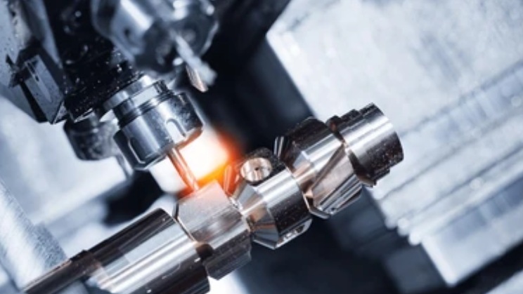
Common CNC Tools Used for Machining Fillets [image source: https://www.shutterstock.com/]
1. Flat End Mills
Flat end mills are the most commonly used tools for machining internal corners in CNC milling. For typical milled inside corners, the smallest achievable internal corner radius is approximately the tool radius. In other words, the end mill corner radius effectively sets the smallest inside corner that can be milled in a single pass. The end mill corner radius, therefore, becomes the limiting factor for how sharp an inside corner can be milled without secondary processes. Choosing standard tool sizes helps reduce cycle time, improve rigidity, and simplify CNC programming and toolpath planning.
2. Corner-Radius End Mills
Corner-radius end mills have a small radius at the tool corner. They’re used to improve edge strength, reduce chipping, and lower corner wear compared with sharp-corner end mills—especially on parts that require consistent edge durability.
3. Ball End Mills
Ball end mills are commonly used for 3D fillets and complex curved surfaces. Their spherical profile creates smooth transitions, but machining is often slower than with flat end mills, especially for small radii.
4. Form Cutters
Form cutters are purpose-made tools that will cut a fixed radius of fillet using one cut. They are utilized most frequently in high-volume manufacturing or reusable geometries when regular radii and short cycle times make custom tooling worth the cost.
Machining Limitations and Minimum Fillet Radius
The radius of the fillet is limited by:
● Tool diameter
● Tool length-to-diameter ratio and tool reach
● Material hardness
● Machine rigidity
A practical fillet radius recommendation for CNC machining:
● Select the largest practicable fillet radius.
● Maintain internal fillets across the part.
● Smaller fillet radii dramatically increase machining complexity and overall manufacturing cost.
Recommended Internal Fillet Radius vs Pocket Depth
Rule of thumb: as pocket depth increases, the inside corner radius in milling should increase to allow larger, more rigid tools and reduce cycle time.
| Pocket depth (H) | Suggested end mill diameter range (D) | Suggested minimum fillet radius (R) | Notes (material, finish) |
| ≤ 3 mm | 1–2 mm | R0.5–1.0 mm | R0.5 mm is achievable at shallow depth; hard materials may require larger radii. |
| 3–10 mm | 2–4 mm | R1.0–1.5 mm | Use larger radii to maintain tool rigidity and a stable surface finish. |
| 10–20 mm | 4–6 mm | R1.5–2.5 mm | Deep pockets increase deflection risk; prioritize consistent radii and accessible toolpaths. |
| 20–40 mm | 6–10 mm | R2.5–4.5 mm | Consider redesign to reduce depth, add reliefs, or split features if radii become too constrained. |
Fillet Design Guidelines for CNC-Machined Parts
In CAD, fillets are usually added with edge- or feature-based tools by specifying a radius. For CNC machining, the key is that the chosen radii should match practical tool sizes—consistent, standard radii reduce tool changes and simplify CAM programming.
Fillet In Engineering [image source: https://www.shutterstock.com/ AI Edited]
A good fillet design balances strength, tool accessibility, and manufacturing cost. Using consistent, practical radii makes parts easier to machine and improves long-term performance.
Fillet Radius Selection in CAD Models
In detailing fillets in CAD, the designer should take into account not only tooling constraints but also business needs to prevent some form of unwarranted machining complexity.
● Machining: The standard fillet radius values are used to ensure that no special tooling is necessary, which uses familiar end mill sizes.
● Make internal fillet radii reproducible throughout the part to simplify the CAM programming and minimize tool changes.
● Avoid micro-fillets—very small radii often increase cycle time and tool wear without improving function.
● Select fillet size according to the availability of tools in the market, where standard tool cutters can be used to efficiently machine the selected radius.
● Scale internal fillet radii with pocket depth and tool accessibility.
Design Tips to Improve CNC Machinability and Part Strength
Other than the basic radius selection, fillets must be used strategically to enhance machining stability, structural integrity, and quality of the part.
1. Increase internal fillet radius whenever possible so that it can take larger cutting tools that are stronger and more rigid.
2. Avoid mixing many different fillet sizes, as it is more difficult to program and expensive to machine.
3. Apply fillets in load-bearing sections, as opposed to sharp corners, to decrease stress concentration and enhance fatigue life.
4. Report essential fillet dimensions graphically on drawings, particularly where strength or fit is functional.
5. Plan fillets, also designed fillets, will enhance CNC, structural performance, and economy.
Common Fillet Design Mistakes and Fixes
● Mistake: Too many different radii across the same part.
Fix: Unify radii where futhe nction allows to reduce tool changes, CAM complexity, and cycle time.
● Mistake: Tiny fillets specified in deep pockets.
Fix: Increase the internal corner fillet radius or redesign the feature to improve tool rigidity and reduce machining risk.
● Mistake: Fillets were added late in the design, causing rework.
Fix: Plan fillets early in CAD and align radii with standard tooling during the first DFM review.
● Mistake: Internal sharp corners demanded without secondary processes.
Fix: Specify EDM/corner cleaning where required, or redesign with an allowable radius to control cost and lead time.
When to Use Fillets in CNC Machining
Fillets aren’t just cosmetic. In CNC machining, they’re often required for tool access, and they can also improve strength, fatigue life, and handling depending on the application.
1. Fillets Are Required for Machinability in Critical Internal Corners
Any internal corner made with CNC machining should have a fillet since sharp intersections cannot be made with round cutting tools. Zero-radius inside corners can only be done by secondary processes like EDM, which add to costs and lead time. Internal fillets are a basic requirement for manufacturable geometry in the case of normal CNC machining.
2. Fillets Reduce Stress Concentrations and Improve Part Longevity
Fillets reduce stress concentration by smoothing sharp geometric transitions. This is particularly unfavorable in high-load components, fatigue-loaded parts, and thin-wall structures, where acute corners could be the cause of cracking or early failure. Filling with the right-sized fillets enhances service life, reliability, and longevity.
3. Optional Fillet Use Cases That Improve Handling, Assembly, or Aesthetics
Aesthetic requirements are also met with fillets designed to enhance the safety and visual quality of handling. They eliminate sharp edges, have smoother transitions between surfaces, and improve the overall appearance and perceived quality of the finished parts.
Fillet Cost Considerations in CNC Machining
CNC cost directly depends on the fillet design. Let’s discuss in depth.
How Fillet Size and Consistency Affect CNC Machining Cost
Cost increases when:
● The fillet radius is very small
● Several sizes of fillets are utilized.
● Special tooling is required
● Additional tool movements are required.
Larger fillets make life cycle time and programming simpler.
Cost Trade-Offs Between Fillets and Chamfers
Fillets can, however, offer improved mechanical performance. The selection of chamfer vs fillet must strike a balance between cost and functionality.
● They are faster to machine.
● Require simpler tools.
● A bit easier to program

High-Precision CNC Fillet Machining at JLCCNC
JLCCNC’s Capabilities for Fillet CNC Machining:
● Minimum internal fillet radius: R0.5 mm (for depth ≤3 mm).
● Default internal-corner capability by pocket depth: for a pocket depth H (mm), our standard milling approach typically follows
R≈(H/10)+0.5, D≈H/5
where R is the minimum internal corner radius and D is the recommended end mill diameter (mm).
● Tooling-based fillet ranges: we select tool diameter and reach based on feature depth; larger radii enable more rigid tools, faster machining, and better consistency.
● Sharp-corner requirements: if sharp internal corners must be retained, we can support secondary processes such as spark erosion corner cleaning, or we can recommend design modifications using radii to reduce cost.
For the complete radius-to-depth rule set and tool diameter mapping, refer to our CNC Machining Design Guideline.
Conclusion
Fillets improve CNC part durability and machinability, especially in internal corners limited by tooling. To control cost, choose the largest practical radii and keep radii consistent across the part. Use fillets for stress-critical transitions, and use chamfers when you mainly need a simple edge break or assembly lead-in.
FAQ
What is a fillet in CNC machining?
A fillet is a rounded corner defined by a radius R, used to replace a sharp edge on CNC-machined parts.
What is the minimum fillet radius CNC machining can achieve?
The minimum achievable internal fillet radius depends on pocket depth and tool access. As a general baseline, R0.5 mm is achievable for depth ≤ 3 mm; deeper features typically require a larger radius to maintain tool rigidity and process stability.
Why do small fillets increase machining cost?
Smaller radii require smaller end mills and often longer tool reach, which reduces rigidity. This typically leads to slower feeds, more passes, higher tool wear, and longer cycle time, increasing overall cost.
How do I design an internal corner if I need it sharp?
True sharp internal corners cannot be produced by standard milling. If a sharp corner is function-critical, specify a secondary process such as EDM or corner cleaning, or redesign the feature with an allowable internal radius to reduce cost and lead time.
Why do internal corners need fillets in CNC machining?
Because milling cutters are round, CNC machining can’t create perfectly sharp inside corners without extra processes like EDM.
Chamfer vs fillet: which is better?
Fillets are better for stress reduction and fatigue life. Chamfers are usually better for quick edge breaks, lead-ins, and lower machining costs.
How are fillets machined?
Fillets are machined using end mills (flat, corner-radius, or ball end mills), depending on the radius and surface geometry.
Are fillets more expensive than chamfers?
Often yes—small or inconsistent fillet radii can increase cycle time and tooling changes. Chamfers are typically faster and cheaper to machine.
Popular Articles
• Cutting with Precision: A Comprehensive Guide to CNC Water Jet Technology
• CNC Coolant Explained: Types, Maintenance & Safety
• Rake Angle in Machining: Machinists’ Guide to Perfect Cuts
• What Steps Are Taken To Minimize Waste In CNC Machining Processes?
• How EDM Wire Cutting Works: Complete Guide to Precision CNC Wire Cutting
Keep Learning
Chatter in Machining: Causes, Effects, and How to Reduce It
CNC milling operation producing visible chatter marks on an aluminum workpiece Quick Chatter Diagnosis Checklist Symptom Most Likely Cause First Action High-pitched squeal Regenerative chatter Change spindle speed ±15% Chatter only in deep pockets Excessive tool overhang Shorten tool Chatter on thin walls Low workpiece rigidity Improve fixturing Chatter after tool replacement Runout / holder issue Check tool holder Chatter only during finishing DOC too small / rubbing Increase feed or adjust speed It ......
What Is Tool Offset in CNC? Types, Setup & Best Practices
CNC tool offset setup with measurement overlay Key Takeaways CNC offsets connect programmed intent with actual cutter position. Length data guides Z-axis depth control. Radius data protects part size during contour milling. Geometry values define the cutter's measured baseline. Wear values support fine correction during production. Verified data lowers scrap risk before full machining. Good offset habits protect tools, fixtures, and parts. In the context of CNC machining , tool offset is the quiet set......
Trochoidal Milling: Complete Guide to High-Efficiency CNC Machining
Key Takeaways Trochoidal milling combines circular cutter motion with continuous forward feed. The cutter normally engages 5 to 20% of its diameter instead of making a full-width cut. A smaller engagement angle limits force changes during slotting and pocket roughing. Low radial engagement often allows greater axial depths of cut than conventional slot milling. CAM software calculates the circular path automatically from the selected machining parameters. This strategy is widely applied to titanium, s......
What Is Die Casting? Process, Materials, and Applications
Key Takeaways Die casting is a metal casting process that forces molten metal into a reusable steel mold under high pressure, producing parts with tight tolerances and good surface finish at high volume. Aluminum die casting is the most common form by far, thanks to its combination of light weight, decent strength, and good corrosion resistance. The die casting process runs through mold preparation, injection, cooling, and ejection in a cycle that can repeat every few seconds to minutes depending on p......
First Angle vs Third Angle: Understanding Orthographic Projection Methods
Key Takeaways Orthographic projection is the system that lets a 3D part be represented through multiple 2D views, front, top, side, and so on. First angle projection and third angle projection are the two standard methods for arranging those views, and they place views in opposite positions relative to the object. First angle projection is the ISO standard used across most of Europe, India, China, Russia, and many other countries following ISO standards Third angle projection is the standard in the Un......
Micro EDM Machining: Capabilities, Materials, and Applications for Precision Components
Key Takeaways About Micro EDM Machining Only electrically conductive materials can be machined. Hole diameters can reach below 50 μm on specialized equipment. The process produces almost no mechanical cutting force, making it suitable for thin or delicate features. Surface integrity still requires attention because recast layers and heat-affected zones may remain after machining. Micro EDM is often combined with CNC machining, with milling producing the main geometry before EDM finishes critical micro......