Slip Fit Tolerances in CNC Machining: Clearance Control and Assembly Accuracy
24 min
- What Is a Slip Fit in CNC Machining?
- Slip Fit Tolerances and Clearance Ranges
- Standard Slip Fit Tolerance Systems
- How CNC Machining Affects Slip Fit Accuracy
- Manufacturing Methods for Precision Slip Fits
- Slip Fit vs Other Fit Types
- Surface Treatments and Their Impact on Slip Fits
- Common Slip Fit Problems in CNC Assemblies
- Designing Slip Fits for Precision CNC Components
- Conclusion About Slip Fit Tolerances
- FAQ About Slip Fit Tolerances
Key Takeaways About Slip Fit
- A slip fit provides controlled positive clearance between a shaft and bore, allowing free assembly without force while limiting excessive play.
- Typical slip fit clearance ranges from approximately 0.010–0.075 mm on common shaft diameters, though the correct value depends on diameter, application requirements, material behavior, and tolerance system selection.
- ISO fit classes H7/g6 and H8/f7 are widely used standard references for slip fit applications in CNC machining.
- Slip fit performance is controlled by the relationship between shaft and bore tolerance zones rather than by a single nominal dimension.
- Both shaft and bore tolerances must be specified together to achieve predictable assembly behavior and consistent clearance.
- Standard CNC machining processes can achieve most slip fit tolerances, but stable process control, surface finish quality, and accurate inspection determine whether fit consistency can be maintained across production batches.
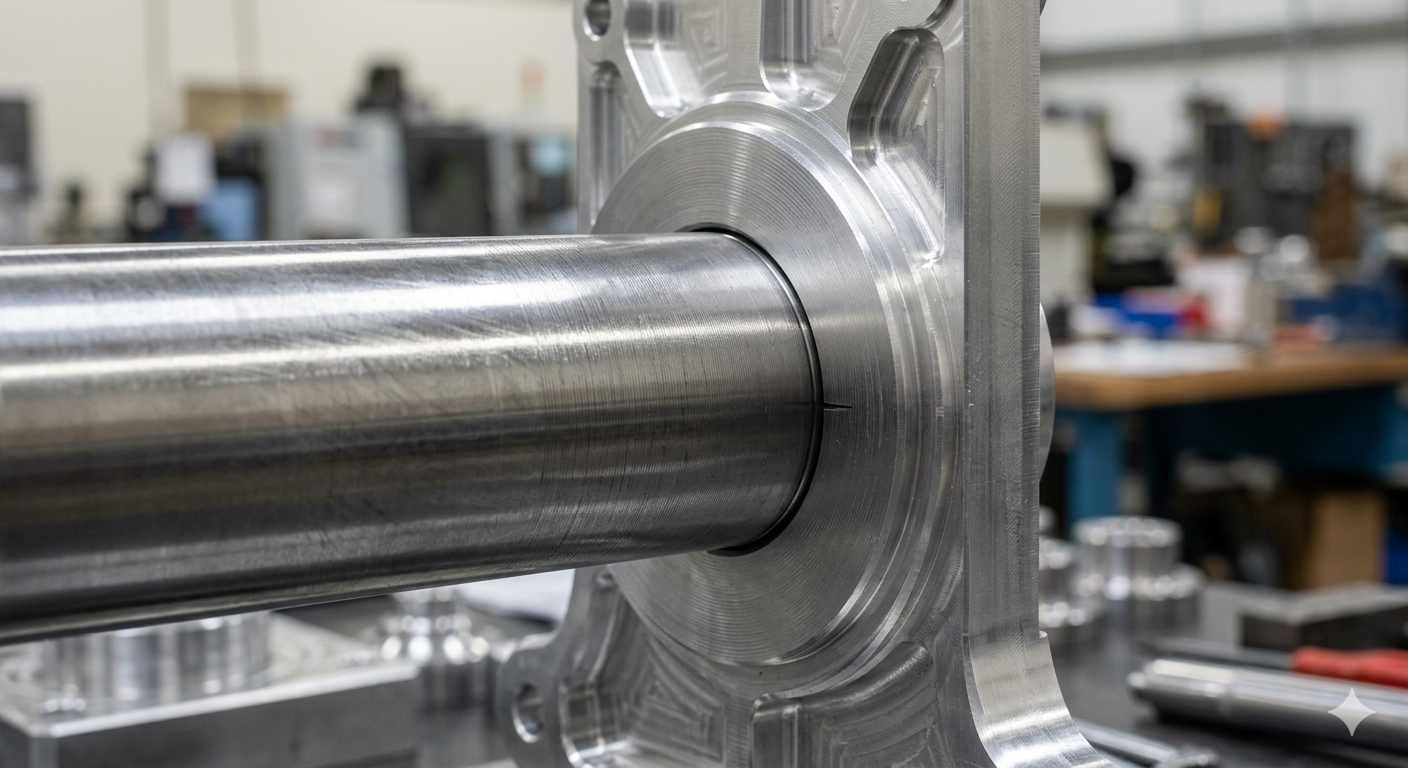
(AI generated) a precision machined shaft sliding into an aluminum housing bore
Here's a scenario that happens more than anyone likes to admit. A shaft and bore come off the machine within their individual tolerances, pass inspection separately, and then don't assemble the way the design intended, either too tight to slide freely or loose enough to rattle. Nobody's dimension is wrong. The fit is wrong. And the fit was wrong because slip fit tolerances weren't defined with enough precision to control what actually matters: the clearance between the two mating surfaces.
Slip fit is one of those terms that gets used loosely in engineering conversations and precisely in manufacturing specifications, and the gap between loose and precise is where assembly problems live. This guide covers what slip fit tolerances actually mean in CNC machining, how clearance is controlled across a shaft-hole relationship, and what the numbers look like when the specification is done correctly.
At JLCCNC, slip fit tolerances are a common requirement across CNC shafts, housings, bushings, fixtures, and precision mechanical assemblies. Holding the nominal diameter is only part of the job. Consistent fit behavior depends on bore geometry, surface finish, machining stability, and inspection control working together across the entire production run.
What Is a Slip Fit in CNC Machining?
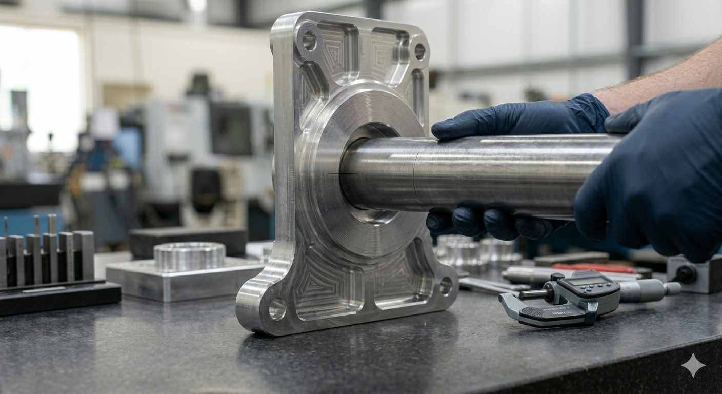
(AI generated) slip fit tolerance measurement
A slip fit is a shaft-to-bore assembly where controlled positive clearance allows the shaft to slide freely into the bore without applied force, while maintaining sufficient contact accuracy for the application's alignment or motion requirements.
That one sentence contains more engineering content than it appears to. "Controlled positive clearance" means the shaft is always smaller than the bore by a defined amount, not by accident, but by specification. "Without applied force" distinguishes a slip fit from a transition or interference fit. "Sufficient contact accuracy" is the part that varies by application. A shaft rotating in a bearing housing has different slip fit clearance requirements than a shaft sliding through a guide bushing under load.
How Slip Fit Geometry Works
In production, the fit problem usually isn't the nominal size itself. It's where the shaft and bore land relative to each other once both tolerances stack together. This is the part that confuses engineers who are used to thinking about individual dimensions rather than fits.
Take a 25mm nominal diameter shaft and bore.
If the bore is specified H7, which for 25mm gives a tolerance band of +0.000/+0.021mm above nominal, so 25.000–25.021mm, and the shaft is specified g6, which gives -0.007/-0.020mm below nominal, so 24.980–24.993mm, then the minimum clearance in the assembly is
25.000 minus 24.993 = 0.007mm,
and the maximum clearance is
25.021 minus 24.980 = 0.041mm.
The slip fit clearance range for this combination is approximately 0.007–0.041mm, entirely positive, meaning the shaft is always smaller than the bore, regardless of where each part lands within its tolerance.
That theoretically guaranteed positive clearance is what makes it a slip fit rather than a transition fit. In a transition fit, the tolerance bands overlap. Some combinations of in-tolerance shaft and bore produce clearance, others produce interference. A properly specified slip fit tolerance eliminates that ambiguity. Every in-tolerance part assembles freely.
The practical implication for CNC machining is that both tolerances need to be specified and held simultaneously. A bore machined to H7 paired with a shaft at an unspecified or nominal diameter isn't a defined slip fit. It's an undefined fit that might assemble freely or might not depending on where the shaft lands.
Where Slip Fits Are Commonly Used:
- Rotating shafts in housing bores where smooth rotation and controlled alignment are required
- Linear motion systems, like guide bushings, pistons, and valve stems
- Precision locating pins and removable tooling fixtures
- Mixed-fit assemblies where press fit and slip fit features exist on the same component
- Bearing support locations requiring free assembly without binding
- High-volume assembly lines where predictable, force-free assembly matters
- Sliding mechanical interfaces affected by load, lubrication, and thermal expansion
- Removable machine components that need repeatable positioning without wear or damage
Slip Fit Tolerances and Clearance Ranges
Slip Fit Clearance and Tolerance Fundamentals
Slip fit clearance is defined as a clearance range rather than a single value. Minimum clearance occurs when the shaft is at its largest permitted size, and the bore is at its smallest. Maximum clearance occurs when the shaft is smallest, and the bore is largest within tolerance.
Minimum clearance determines whether the assembly remains truly slip-fit under worst-case conditions. If clearance reaches zero or becomes negative, some in-tolerance parts may require force during assembly, effectively behaving like a transition fit. In most CNC-machined slip fits, practical minimum clearance typically stays around 0.005–0.010mm to maintain reliable free assembly while accounting for surface finish variation, thermal effects, and minor geometric error.
Maximum clearance controls how much movement the assembly allows during operation. Precision locating features often keep maximum slip fit clearance below roughly 0.030 mm, while general sliding components may allow 0.050–0.100 mm or more depending on alignment requirements.
The difference between minimum and maximum clearance reflects the combined shaft and bore tolerance bands. Narrower tolerance ranges produce more consistent fit behavior across production batches, while wider tolerances increase assembly variation.
Common Slip Fit Tolerance Classes
For most slip fit applications in CNC machining, a handful of standard tolerance combinations cover the majority of real engineering requirements.
H7/g6 is one of the most common precision slip fit classes for rotating shafts, locating features, and general precision assemblies. For a 25mm diameter shaft, this produces approximately 0.007–0.040mm
clearance range. For a 50mm diameter, the same class produces approximately 0.009–0.050mm. The clearance scales with diameter because absolute tolerances widen as nominal size increases while the fit character stays consistent. H7/g6 is the starting point for most precision slip fit specifications in metric CNC machining.
H8/f7 produces more clearance, typically 1.5–2x the clearance of H7/g6 at equivalent diameters. For a 25mm shaft, H8/f7 gives approximately 0.020–0.074mm clearance. This class suits applications where free sliding under load is more important than tight alignment, guide shafts, sliding sleeves, and components that need to move freely without lubrication in some cases.
H9/d9 and H11/c11 are running fit classes with substantially more clearance, used for shafts in plain bearings, loose sliding fits, and assemblies where thermal expansion variation is significant. These are engineering fits rather than precision fits, the clearance is intentional and generous rather than minimized.
For tight slip fits approaching transition territory, precision locating pins, gauge components, and features where maximum clearance needs to stay below 0.020mm, H6/g5 or H7/h6 (the latter often considered a line-to-line or very tight clearance fit near the transition boundary) are used. These require tighter machining capability and more rigorous process control to hold consistently.
Clearance Behavior in Real Assemblies
Specified slip fit clearance and actual assembly behavior don't always match as cleanly as the tolerance math suggests. Several factors push real clearance away from the theoretical range.
Surface finish consumes effective clearance. A bore with Ra 1.6 µm and a shaft with Ra 0.8 µm have surface peaks that reduce effective clearance below what the diameter measurements indicate. For tight slip fits where minimum clearance is already small, surface finish specification matters, a bore measured at 25.005mm but with 3.2 µm Ra surface finish effectively behaves like a slightly smaller bore under sliding contact. Specifying Ra 0.8 µm or better on precision slip fit surfaces is standard practice for this reason.
Thermal expansion shifts clearance during operation. A steel shaft in an aluminum bore at 25mm nominal with H7/g6 clearance at room temperature will usually see that clearance increase during operation because aluminum expands roughly twice as much as steel as the temperature rises. At a 50°C temperature rise, the aluminum bore grows roughly 0.01–0.015 mm more than the steel shaft on a 25mm diameter, potentially making the fit looser than intended. For mixed-material assemblies in thermal environments, clearance needs to be calculated at operating temperature, not just at room temperature.
Geometric errors such as out-of-roundness, taper, and straightness deviation affect assembly behavior independently of diameter tolerance. A bore that measures correctly at two cross-sections but has 0.015mm of taper along its length will produce a fit that's looser at one end than the other. For precision slip fit assemblies where alignment matters across the full contact length, cylindricity and straightness tolerances on the drawing are as important as the diameter tolerance.
Need precision slip fit shafts, bores, or tight-tolerance CNC assemblies? JLCCNC CNC machining services support reaming, boring, grinding, and production machining for custom mechanical components with tolerances tailored to real assembly performance, not just drawing dimensions.

Precision CNC Machining Service
Professional manufacturing, fast turnaround, and quality assurance.
Standard Slip Fit Tolerance Systems
ISO Hole and Shaft Fit System
The ISO system, defined in ISO 286, is the standard reference for slip fit tolerances in metric CNC machining worldwide. It uses a letter-number designation where the letter defines the position of the tolerance band relative to nominal size and the number defines the tolerance grade width.
For holes, uppercase letters define the band position. H is the fundamental designation for the most common hole basis fits. The H tolerance band starts at nominal size and opens upward, meaning the minimum hole size is always at or above nominal. This is intentional: it means a correctly specified H-basis slip fit always has the bore at or above nominal, and the shaft below nominal, guaranteeing positive clearance when the shaft tolerance is also correctly specified.
For shafts, lowercase letters define the band position relative to the nominal. Letters further from h in the alphabet (f, e, d) place the shaft tolerance band progressively further below nominal, producing more clearance. Letters closer to h (g, h) place the shaft closer to nominal, producing tighter fits. g produces a small negative offset from nominal. The shaft is always slightly below nominal size, which is why H7/g6 produces a small but guaranteed positive minimum clearance.
Tolerance grade numbers (IT grades) define band width, IT6 is tighter than IT7, which is tighter than IT8. IT6 tolerance on a 25mm feature is 0.013mm. IT7 is 0.021mm. IT8 is 0.033mm. Combining H7 bore with g6 shaft means the bore has IT7 width and the shaft has IT6 width. The shaft is held to a tighter grade than the bore, which is standard practice since shafts are generally easier to measure and control than bores.
ANSI and RC Fit Classes
The ANSI B4.1 system uses running and sliding fit classes, RC1 through RC9, that define clearance ranges directly rather than through letter-number designations. RC fits are the ANSI running and sliding fit classification system commonly used in inch-based drawings.
RC1 and RC2 are close sliding fits, with minimum clearance near zero, used for precision sliding components where accurate location matters. RC3 and RC4 are precision running fits, the most commonly used ANSI slip fit classes for rotating shafts and general precision assemblies. RC5 and RC6 are medium running fits with more clearance for higher speeds or less precise applications. RC7 through RC9 are free-running fits with generous clearance for high speeds, wide temperature ranges, or applications where alignment precision is secondary.
The RC system specifies clearance limits directly in the standard tables for each nominal size range, which makes it straightforward to use without calculating from tolerance band positions. For a 1.000" (25.4mm) shaft in RC3 fit, the standard specifies 0.0005"–0.0015" clearance (0.013–0.038mm), comparable to H7/g6 in the ISO system at equivalent diameter.
The practical difference between ISO and ANSI RC fits is documentation and regional preference rather than engineering capability. ISO is dominant in metric CNC machining globally. ANSI RC fits appear more commonly in North American inch-system drawings. Both systems produce equivalent fits when the correct class is selected. Conversion between them is straightforward for standard slip fit applications.
Selecting Standard Slip Fit Classes
Slip fit class selection follows from three application requirements: required minimum clearance, required maximum clearance, and the machining capability available to hold the specified tolerances.
Start with the application's alignment requirement. If the slip fit needs to locate a component within 0.020mm, maximum clearance can't exceed 0.020mm, that rules out H8/f7 and pushes toward H7/g6 or tighter. If alignment within 0.050mm is acceptable, H8/f7 becomes viable and easier to hold in production.
Check the thermal environment. If operating temperature varies significantly or materials differ between shaft and bore, calculate the clearance at maximum operating temperature and ensure minimum clearance remains positive. If it doesn't, the nominal class needs more clearance than the room-temperature alignment requirement alone would suggest.
Match to machining capability. H7/g6 requires a bore tolerance of 0.021mm and a shaft tolerance of 0.013mm on a 25mm feature, achievable on standard CNC turning and boring equipment with proper tooling and measurement, but requiring process control and in-process gauging to hold consistently across a production run. H6/g5 tightens both by roughly 40%, achievable but requiring more capable equipment and tighter process discipline. Specifying tighter than the shop's demonstrated capability produces a drawing that looks correct and parts that require 100% inspection and sorting to meet the fit requirement.
For most general precision slip fit applications in CNC machining, H7/g6 is often the practical starting point for many precision CNC slip fit applications. It produces reliable positive clearance, is achievable on standard CNC equipment, and is well-understood enough that most machinists and inspectors know what it means without additional explanation.
How CNC Machining Affects Slip Fit Accuracy
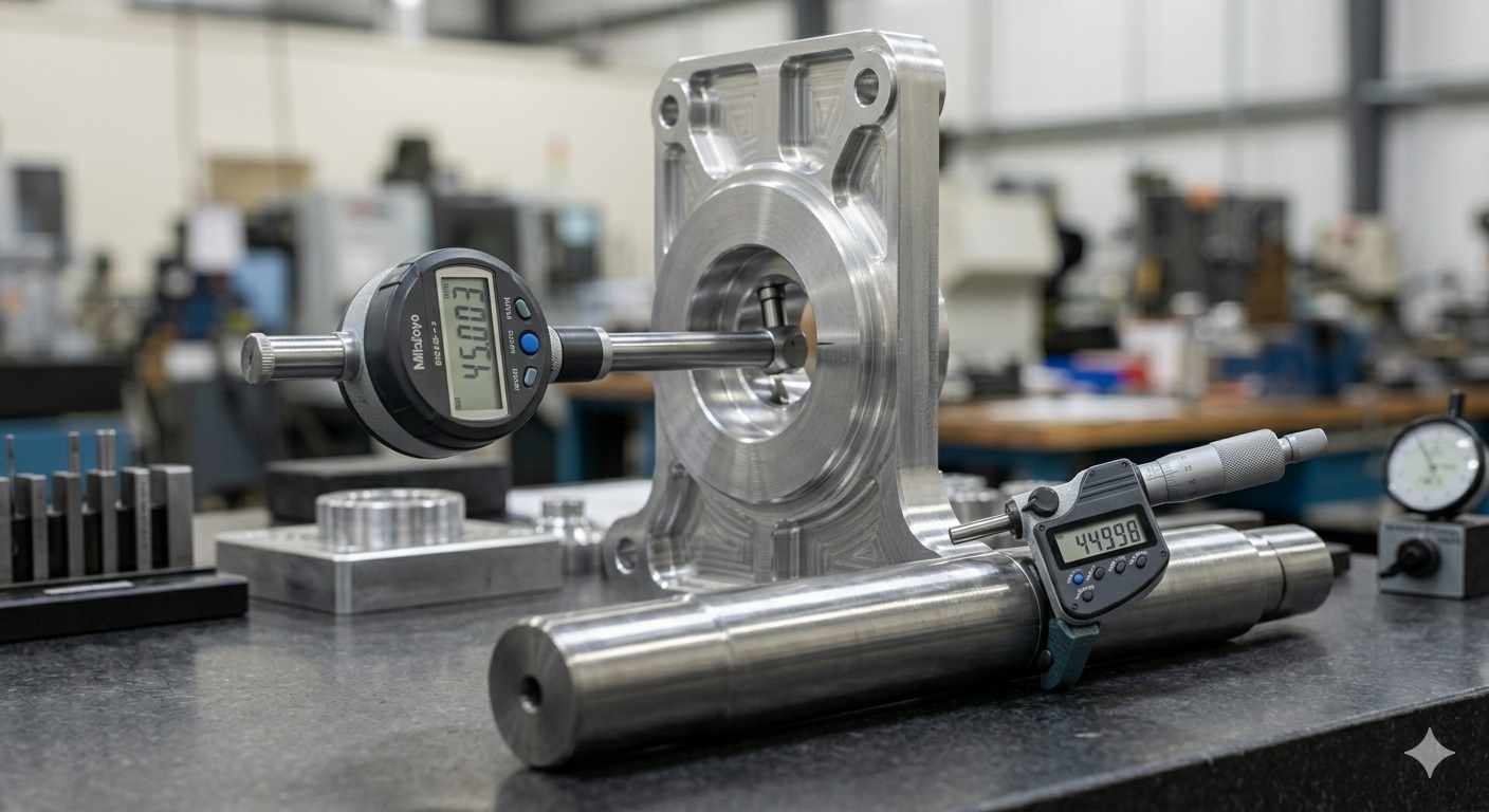
(AI generated) shaft being test-fitted into a bore during slip fit inspection
Slip fit accuracy depends less on the drawing and more on how stable the machining process stays during production. A machine may technically hold ±0.005mm, but thermal drift, tool wear, spindle growth, setup rigidity, and cutting forces all push against the available clearance window at the same time.
And slip fits expose those errors immediately. A loose bracket hole can hide variation. A shaft sliding into a precision bore cannot.
Bore Accuracy and Shaft Consistency
Shaft diameters are usually easier to control because turning naturally produces round geometry as the part rotates concentrically with the spindle. Bores are harder. Precision shaft geometry, concentricity control, bearing seats, and runout management are discussed further in JLCCNC’s shaft machining guide.
Boring bars behave like cantilevers. As bore depth increases or bar diameter decreases, tool deflection starts affecting size, taper, and straightness simultaneously. Material behavior adds more variation. Aluminum expands with heat while stainless steel tends to work harden and resist cutting forces.
Tool wear matters too. Shaft turning tools often wear predictably enough for offset compensation. Boring tools are usually less stable because vibration and chip evacuation affect the cut inside the bore.
Inspection and Tolerance Verification
Slip fit inspection becomes unreliable when only size is checked.
A shaft may pass diameter inspection while still containing lobing or taper severe enough to affect assembly feel. The same applies to bores with out-of-round conditions.
Micrometers and bore gauges remain standard for production inspection, but operator technique, part temperature, and even measuring force can influence readings at micron-level tolerances. Higher-precision production often uses air gauges or CMM inspection to verify roundness, cylindricity, and positional accuracy alongside size.
But inspection alone cannot fix an unstable process. Shops that hold consistent slip fits usually focus more on machining stability than sorting parts after measurement.
Manufacturing Methods for Precision Slip Fits
Precision slip fits are rarely the result of a single machining operation.
They're usually the result of staged machining where roughing establishes geometry, semi-finishing stabilizes the feature, and finishing operations bring the fit into its final tolerance range with predictable surface behavior.
The tighter the slip fit requirement gets, the more process selection starts mattering.
Not every machining method produces the same geometry quality, even if the final measured diameter appears identical. Some operations naturally generate straighter bores, better roundness, or more stable surface finish. Others prioritize speed and flexibility at the expense of ultimate fit consistency.
Choosing the right process is often the difference between a fit that works occasionally and one that works every time.
CNC Milling vs Reaming Accuracy
Interpolated CNC milling can produce acceptable slip fit bores for general applications, particularly where clearance requirements are moderate.
For tighter slip fits, reaming is often preferred because it improves bore roundness, cylindricity, and surface consistency more reliably than interpolation alone.
However, reaming still depends on proper pre-drill size, tool condition, and stable cutting parameters. Most precision bores are rough-machined first, then finished with a controlled reaming allowance.
Boring vs Reaming for Slip Fits
Boring offers finer diameter adjustment than reaming and is commonly used for custom slip fit tolerances or larger bores.
Because boring is sensitive to tool deflection, spindle stability, and thermal drift, finishing passes are usually conservative when tight fit consistency is required.
Reaming is generally faster and more repeatable in production, while boring provides greater flexibility for precision diameter control.
Grinding for Tight Tolerance Shafts
For very tight shaft tolerances, grinding is often used after heat treatment to improve roundness, surface finish, and dimensional stability beyond what standard turning can consistently maintain.
This is common in bearing shafts, hydraulic components, and precision rotating assemblies where micron-level geometry control affects fit performance directly.
Slip Fit vs Other Fit Types
Slip fits are only one category within shaft-to-hole fit systems. The differences become clearer when compared with clearance, transition, and interference fits.
| Fit Type | Clearance Condition | Assembly Method | Movement After Assembly | Typical CNC Applications | Manufacturing Difficulty | Risk if Specified Incorrectly |
|---|---|---|---|---|---|---|
| Slip Fit | Always positive controlled clearance | Hand assembly without force | Free sliding or rotation with controlled play | Guide shafts, locating pins, removable tooling, bearing housings | Moderate | Binding from thermal growth or excessive looseness |
| Clearance Fit | Positive clearance, often larger and less controlled | Easy assembly | Significant movement possible | Covers, brackets, non-precision alignment features | Low | Excessive vibration, positional inaccuracy |
| Transition Fit | Clearance or slight interference depending on tolerance stack | Light pressing or selective assembly | Minimal movement | Gears, pulleys, precise locating features | High | Inconsistent assembly behavior between parts |
| Press Fit | Always negative clearance (interference) | Force, hydraulic press, or thermal assembly | No relative movement intended | Bushings, bearings, permanent shaft-hub assemblies | High | Cracking, distortion, assembly failure |
A properly designed slip fit should feel controlled but effortless. The shaft enters smoothly without noticeable force while still maintaining alignment. A loose clearance fit feels forgiving because positional accuracy is not the priority. A transition fit feels unpredictable because one assembly may slide together while the next suddenly needs force. A press fit feels deliberate from the beginning because the interference is intentional.
Surface Treatments and Their Impact on Slip Fits
| Surface Treatment | Typical Thickness Build-Up | Effect on Slip Fit Clearance | Common Manufacturing Concern | Typical Compensation Method |
|---|---|---|---|---|
| Type II Anodizing | ~0.005–0.025 mm total buildup | Reduces clearance on shafts and bores | Tight sliding or inconsistent assembly after coating | Machine undersize before anodizing |
| Hardcoat Anodizing (Type III) | ~0.025–0.075 mm total buildup | Significantly reduces clearance due to thicker oxide growth | Slip fit turning into transition or interference fit | Increase pre-coating clearance allowance |
| Nickel Plating | ~0.010–0.050 mm per side | Can substantially tighten precision fits | Bore shrinkage, shaft oversize, localized binding | Precision masking or post-machining |
| Chrome Plating | ~0.005–0.025 mm per side | Reduces clearance while increasing surface hardness | Variable plating thickness affecting insertion force | Finish grind after plating on precision shafts |
| Electroless Nickel | ~0.005–0.025 mm highly uniform buildup | Predictable clearance reduction due to even deposition | Tight fit when tolerance stack is already aggressive | Controlled pre-machining offsets |
| Black Oxide | Minimal measurable buildup | Negligible dimensional impact on most slip fits | Limited corrosion protection compared with thicker coatings | Usually no dimensional compensation required |
Common Slip Fit Problems in CNC Assemblies
| Slip Fit Problem | What Happens in Assembly | Typical Manufacturing Cause | Real Dimensional Scenario | Operational Consequences | Common Engineering Fix |
|---|---|---|---|---|---|
| Slip fit becomes unexpectedly tight | Shaft drags, sticks, or requires force during assembly | Bore undersize from tool wear, thermal drift, or coating buildup | Intended clearance 0.015mm reduced to near-zero after anodizing adds ~0.012mm total buildup | Galling, seizure risk, assembly slowdowns | Increase pre-coating clearance allowance or loosen fit class |
| Shaft binds only at certain positions | Fit feels inconsistent during insertion or rotation | Bore taper, lobing, or shaft roundness error | Bore varies 0.008mm across length despite acceptable average diameter | Uneven wear, rotational resistance | Add cylindricity and roundness controls |
| Assembly passes inspection but fails under heat | Fit tightens during operation | Thermal expansion mismatch between materials | A steel shaft operating significantly hotter than a surrounding steel housing may reduce clearance during operation due to differential thermal expansion. | Seizing during runtime | Design additional thermal clearance |
| Excessive clearance causes vibration | Shaft rattles or shifts under load | Overly loose fit class or oversized bore | 25mm shaft with >0.080mm clearance instead of intended ~0.020mm | Runout, noise, reduced positional accuracy | Tighten shaft tolerance band |
| Parts assemble differently across production batches | Some assemblies slide freely while others require fitting | Tool wear progression or unstable process control | Early batch bores at +0.005mm, later batch drifts toward lower limit | Sorting, inconsistent assembly force | Scheduled tool replacement and SPC monitoring |
| Slip fit becomes interference after plating | Components no longer assemble post-finish | Nickel or chrome plating not compensated in machining | 0.020mm nickel buildup consumes entire designed clearance | Rework or scrap | Machine undersize before plating |
| Fit loosens over time | Initial assembly acceptable but develops movement during service | Wear from insufficient hardness or contamination | Repeated sliding enlarges effective clearance beyond design range | Positional instability, chatter | Harden surfaces or improve lubrication |
| Tight fit despite correct diameter readings | Assembly feels rough even though inspection passes | Poor surface finish or burr formation | Ra >3.2µm roughness consumes meaningful portion of tight clearance | Stick-slip motion, inconsistent insertion | Reaming, honing, deburring |
| Multi-bore assemblies bind during installation | Shafts fit individually but fail when assembled together | Positional tolerance stack-up | Multiple bores drift ~0.03mm off true position | Forced assembly, component stress | Tighten GD&T positional control |
| Thin-wall bore distorts after clamping | Fit changes after installation into housing | Residual stress release or clamp deformation | Bore closes several microns after fasteners are torqued | Assembly inconsistency after installation | Simulate clamp conditions during machining and inspection |
Designing Slip Fits for Precision CNC Components
A good slip fit is designed around assembly behavior, not just nominal dimensions. A removable locating pin can tolerate far more clearance than a high-speed rotating shaft, even at the same diameter.
Most CNC slip fits run between 0.005mm and 0.050mm clearance, depending on size and application. Small precision fits using H7/g6 may run near 0.004–0.006mm clearance, while larger removable shafts often target 0.025–0.060mm to handle thermal growth and alignment variation.
Matching Fit Tolerance to Functional Requirements
High-speed rotating assemblies usually need tighter radial control than slow-moving sliding components. But tighter clearances increase machining cost quickly because tooling, thermal stability, surface finish, and inspection become far more sensitive.
A fit that theoretically works at 0.003mm clearance may become impractical in production if parts require constant adjustment or sorting.
Material Effects on Slip Fit Performance
Material choice changes fit behavior even when dimensions stay identical.
Aluminum expands roughly twice as much as steel, so a steel shaft inside an aluminum housing often gains clearance as temperature rises. Reversing the material combination may reduce clearance during operation because the aluminum shaft expands faster than the surrounding steel bore.
Hardness matters too. Soft aluminum wears faster under repeated sliding, while stainless steel can gall if clearances are too tight without lubrication. Hardened and ground shafts generally support tighter, more stable slip fits because surface geometry is more controlled.
Manufacturing Trade-Offs in Tight Slip Fits
Once total clearance drops below roughly 0.010mm, process stability becomes more difficult. Tool wear, thermal drift, and measurement variation start consuming a large percentage of the available tolerance range.
Grinding, honing, or air-gauge inspection may become necessary, cycle times increase, and process control becomes stricter. That is why engineers usually avoid the tightest possible fit unless the application genuinely requires it.
The best slip fit is usually the loosest fit that still controls the assembly properly.
Conclusion About Slip Fit Tolerances
The assembly side determines how much movement, alignment accuracy, and thermal stability the component needs. The manufacturing side determines what geometry can actually be produced repeatedly without turning every production batch into a tolerance investigation.
Because in the end, the best slip fit is not the tightest one.
It's the one that still works exactly the same way on the thousandth assembly as it did on the first.
Need reliable slip fit tolerances for shafts, bores, housings, or precision assemblies? JLCCNC provides CNC machining, precision boring, reaming, grinding, and tight-tolerance production for custom mechanical components with fast turnaround and production-ready inspection support.
Precision CNC Machining Service
Professional manufacturing, fast turnaround, and quality assurance.
FAQ About Slip Fit Tolerances
Q: What is a slip fit in machining?
A slip fit is a shaft-to-bore fit with positive clearance so parts assemble freely without force while maintaining controlled alignment.
Q: What is the difference between H7/g6 and H8/f7 slip fits?
H7/g6 is a tighter precision slip fit commonly used for rotating shafts and locating features where alignment accuracy matters. H8/f7 provides more clearance and is often used for freer sliding movement, easier assembly, or applications affected by thermal expansion and contamination.
Q: Can CNC milling achieve slip fit tolerances without reaming?
For moderate slip fit clearances, interpolated CNC milling may be sufficient. Tighter slip fits usually require reaming, boring, or grinding to improve bore roundness, surface finish, and dimensional consistency.
Q: What surface finish is recommended for slip fits?
Precision slip fits commonly use surface finishes around Ra 0.8–1.6 µm. Rougher surfaces can increase friction, reduce effective clearance, and create inconsistent sliding behavior even when measured dimensions remain within tolerance.
Q: Can anodizing affect a slip fit?
Yes. Anodizing adds oxide thickness that reduces effective clearance between the shaft and bore. Tight slip fits can shift toward transition or interference behavior if coating thickness is not compensated during machining.
Q: What is the difference between slip fit and press fit?
A slip fit maintains positive clearance for free assembly and movement, while a press fit uses intentional interference to prevent relative motion between components.
Popular Articles
• Cutting with Precision: A Comprehensive Guide to CNC Water Jet Technology
• CNC Coolant Explained: Types, Maintenance & Safety
• Rake Angle in Machining: Machinists’ Guide to Perfect Cuts
• What Steps Are Taken To Minimize Waste In CNC Machining Processes?
• How EDM Wire Cutting Works: Complete Guide to Precision CNC Wire Cutting
Keep Learning
Chatter in Machining: Causes, Effects, and How to Reduce It
CNC milling operation producing visible chatter marks on an aluminum workpiece Quick Chatter Diagnosis Checklist Symptom Most Likely Cause First Action High-pitched squeal Regenerative chatter Change spindle speed ±15% Chatter only in deep pockets Excessive tool overhang Shorten tool Chatter on thin walls Low workpiece rigidity Improve fixturing Chatter after tool replacement Runout / holder issue Check tool holder Chatter only during finishing DOC too small / rubbing Increase feed or adjust speed It ......
What Is Tool Offset in CNC? Types, Setup & Best Practices
CNC tool offset setup with measurement overlay Key Takeaways CNC offsets connect programmed intent with actual cutter position. Length data guides Z-axis depth control. Radius data protects part size during contour milling. Geometry values define the cutter's measured baseline. Wear values support fine correction during production. Verified data lowers scrap risk before full machining. Good offset habits protect tools, fixtures, and parts. In the context of CNC machining , tool offset is the quiet set......
Trochoidal Milling: Complete Guide to High-Efficiency CNC Machining
Key Takeaways Trochoidal milling combines circular cutter motion with continuous forward feed. The cutter normally engages 5 to 20% of its diameter instead of making a full-width cut. A smaller engagement angle limits force changes during slotting and pocket roughing. Low radial engagement often allows greater axial depths of cut than conventional slot milling. CAM software calculates the circular path automatically from the selected machining parameters. This strategy is widely applied to titanium, s......
What Is Die Casting? Process, Materials, and Applications
Key Takeaways Die casting is a metal casting process that forces molten metal into a reusable steel mold under high pressure, producing parts with tight tolerances and good surface finish at high volume. Aluminum die casting is the most common form by far, thanks to its combination of light weight, decent strength, and good corrosion resistance. The die casting process runs through mold preparation, injection, cooling, and ejection in a cycle that can repeat every few seconds to minutes depending on p......
First Angle vs Third Angle: Understanding Orthographic Projection Methods
Key Takeaways Orthographic projection is the system that lets a 3D part be represented through multiple 2D views, front, top, side, and so on. First angle projection and third angle projection are the two standard methods for arranging those views, and they place views in opposite positions relative to the object. First angle projection is the ISO standard used across most of Europe, India, China, Russia, and many other countries following ISO standards Third angle projection is the standard in the Un......
Micro EDM Machining: Capabilities, Materials, and Applications for Precision Components
Key Takeaways About Micro EDM Machining Only electrically conductive materials can be machined. Hole diameters can reach below 50 μm on specialized equipment. The process produces almost no mechanical cutting force, making it suitable for thin or delicate features. Surface integrity still requires attention because recast layers and heat-affected zones may remain after machining. Micro EDM is often combined with CNC machining, with milling producing the main geometry before EDM finishes critical micro......