Shaft Machining: Process, Methods, and Precision Manufacturing Guide
24 min
- What Is a Shaft?Function and Working Principle
- What is Shaft Machining? Process Definition
- CNC Shaft Machining vs Traditional Machining
- What Are the Common Types of Industrial Shafts?
- What Is the Shaft Machining Process?
- What Are the Different Shaft Shapes and Forms?
- What Materials Are Commonly Used for Shaft Machining?
- What Are the Main Shaft Machining Methods?
- What Is CNC Shaft Machining?
- What Is Precision Shaft Machining?
- What Are the Challenges and Advanced Techniques in Long Shaft Machining?
- Example Workflow: How Is a Stepped Shaft Machined?
- What Factors Affect Shaft Machining Quality?
- What Drives the Cost of Shaft Machining
- What Are the Common Applications of Shaft Machining?
- How to Optimize Shaft Design for Manufacturing?
- How to Choose a Shaft Machining Supplier
- FAQ about Shaft Machining
Key Takeaways
• Shaft machining is the process of making rotating parts with precise diameters, steps, bearing seats, and torque-transfer features.
• CNC shaft machining is preferred for tight tolerances, complex features, and repeatable batch production.
• Precision shaft machining depends on controlling tolerance, runout, concentricity, and surface finish together.
• Turning is the main shaft machining process, while milling, drilling, threading, and grinding are used for features and higher precision.
• Material, geometry, shaft length, and heat treatment directly affect machining difficulty, quality, and cost.
• Long shafts are harder to machine because deflection and vibration increase as the length-to-diameter ratio grows.
• A good shaft machining supplier should be able to control geometry, verify tolerances, and maintain consistency across production.
What Is a Shaft?Function and Working Principle
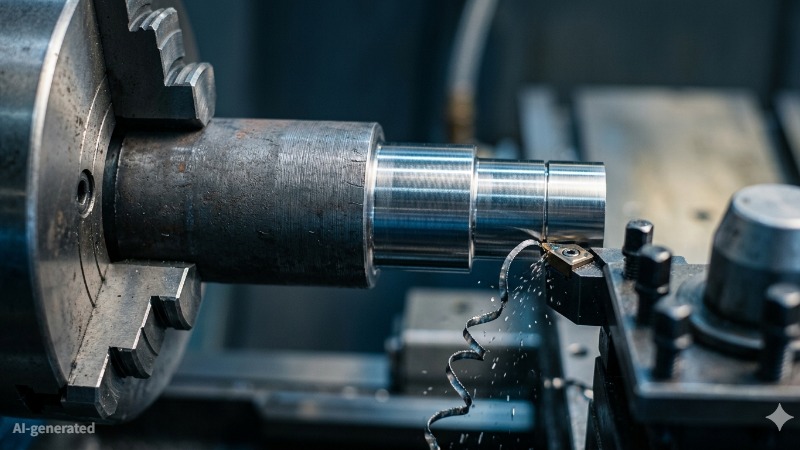
(AI generated) Steel shaft partially machined on CNC lathe
Shaft machining is the process of producing cylindrical rotating parts by turning, milling, drilling, grinding, and finishing operations. It is used to control shaft diameter, bearing fits, runout, surface finish, and functional features such as keyways, threads, and shoulders.
The Basic Concept
A shaft is a cylindrical mechanical component, usually designed to rotate, that transmits torque, supports rotating elements, or both.
The Input: A motor or an engine spins one end.
The Output: A gear, a wheel, or a fan is attached to the other end.
The Shaft: It’s the bridge between them.
Loads on a Shaft: Torsion, Bending, and Vibration
If a shaft was just a spinning stick, it would be easy. But when a machine is running, the shaft is under a massive amount of stress.
Most people think a shaft just spins. In reality, it’s a long spring that's constantly trying to twist itself into pieces. When a motor kicks on, the shaft takes the hit. If the torque is high, the steel actually twists (torsion). If that twist is too much, your timing goes out and the metal starts to fatigue.
But it’s rarely just a twist. Usually, you’ve got a heavy pulley or a gear hanging off the side. That weight is constantly trying to bend the shaft. So as it rotates, the steel is being compressed then stretched, over and over, thousands of times a minute. If you don't have the right diameter or the right heat-treat, that cycle eventually cracks the part.
At high RPMs, if the shaft isn't concentric, meaning all the different steps aren't perfectly centered, it acts like a hammer. It’ll shake the seals out of the housings and chew up the gears.
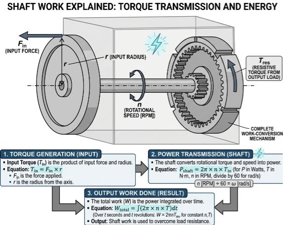
(AI generated) Diagram showing how shafts work
Why Precision Matters in Shaft Design
A shaft might look like a simple metal rod, but the tolerances for precision machining are usually some of the tightest in the shop. For critical bearing seats, even a small deviation can affect fit, vibration, and service life. You’ll either have a loose fit that vibrates or a press-fit so tight it kills the bearing life before you even start the machine.
Concentricity and Balance When a shaft spins at high RPMs, any lack of concentricity turns into a vibration problem. If the different diameters (the steps on a shaft) aren't perfectly aligned to the same center line, the part acts like a weight on a string, pulling the machine apart. This is why CNC turning and grinding are the standard processes. You need that level of control to keep everything centered.
Surface Finish and Friction The finish on a shaft is just as important as the size. In the areas where the shaft sits inside a seal or a bearing, a rough surface will act like sandpaper. It’ll chew through seals and cause oil leaks, or it’ll create enough friction to weld itself to a bushing. Most high-performance shafts end up on a cylindrical grinder after they leave the lathe just to get that mirror finish required for a long service life.
Shaft machining depends on control. If the setup drifts, your tolerance stack fails fast. At JLCCNC, we handle precision shaft machining with tight process control from roughing to final inspection. You get consistent geometry, stable runout, and parts built for real load conditions, not just drawings.

Precision CNC Machining Service
Professional manufacturing, fast turnaround, and quality assurance.
What is Shaft Machining? Process Definition
If a shaft is the bridge that carries power, then shaft machining is the process of making sure that bridge doesn't collapse, vibrate, or seize up the second the motor starts.
A raw piece of steel bar stock is just a hunk of metal. Shaft machining is what turns it into a high-precision tool.
The most important part of shaft machining is the tolerance, which is just a fancy word for how much room for error you have. In most machines, that room for error is less than the thickness of a human hair.
Bearing Seats: Bearings are the parts that let the shaft spin smoothly. If the machinist cuts the shaft even a tiny bit too small, the bearing will just spin on the shaft and create heat until it welds itself shut. If it's too big, you’ll break the bearing trying to hammer it on.
Seal Surfaces: If the shaft goes into a gearbox, it needs a rubber seal to keep the oil in. If the machining finish is rough (like sandpaper), it’ll chew that rubber up in an hour. Shaft machining involves "polishing" those specific spots to a mirror finish.
Adding the Features
A raw bar can't hold a gear. Machining is how we add the keys and shoulders we talked about earlier:
CNC Turning We spin the metal at high speeds on a lathe and use a sharp cutting tool to carve out the different diameters (the steps). This ensures the whole thing is concentric, meaning it doesn't wobble like a bent bike wheel.
Milling the Keyways Once the round shape is done, we move the shaft to a mill to cut the slots for keys or splines. This is where most people mess up; if you don't leave a tiny curve (a radius) in the corner of that slot, the shaft will snap there under pressure.
Grinding For the most critical shafts, turning isn't accurate enough. We use a grinding wheel to shave off microscopic layers of metal to get a perfect, glass-like finish and a size that is accurate down to the micron.
CNC Shaft Machining vs Traditional Machining
| Factor | CNC Shaft Machining | Traditional Machining |
|---|---|---|
| Accuracy | High and consistent. CNC systems routinely hold tight tolerances (±0.005 mm or better) across diameters, shoulders, and features with minimal variation. | Operator-dependent. Skilled machinists can achieve good accuracy, but consistency varies between parts and setups. |
| Repeatability | Excellent. Once programmed, every part follows the same toolpath, maintaining identical dimensions across batches. | Limited. Each part may vary slightly due to manual control, tool wear, and setup differences. |
| Cost | Higher upfront (programming, setup), but lower per-part cost at scale due to reduced labor and scrap. | Lower initial cost for simple or one-off parts, but labor-intensive, making it expensive for larger batches. |
| Scalability | Highly scalable. Ideal for batch production and long runs with minimal additional effort. | Poor scalability. Production speed depends on operator time, making large volumes inefficient. |
In short, CNC shaft machining offers better accuracy, repeatability, and scalability, making it the preferred choice for precision parts and batch production. Traditional machining can still work for simple or one-off shafts, but it becomes less efficient and less consistent as geometry, tolerance, and production volume increase.
What Are the Common Types of Industrial Shafts?
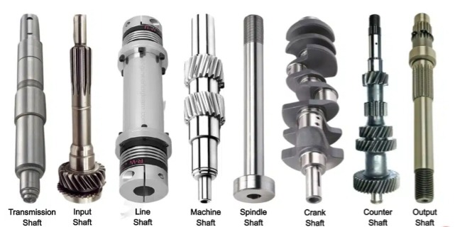
(Engineeringlearn) Types of shaft
People love clean classifications. Reality isn’t that neat.
In actual machines, shafts get named based on what they end up doing, not what some textbook says. Same piece of geometry, different job, different problems.
So instead of memorizing categories, think in terms of load, speed, and what’s mounted on it.
Transmission Shafts, Machine Shafts, and Structural Shafts
| Type | What it actually means in real use | Where it shows up | What you need to care about |
|---|---|---|---|
| Transmission shaft | It exists to move torque from A to B | Old-school line shafts, gear trains, belt systems | Torsion and alignment. If it twists too much or runs out, everything downstream suffers |
| Machine shaft | It’s part of the machine itself, not just connecting things | Pump shafts, lathe shafts, compressor internals | Fits, runout, surface finish. This is where bad tolerances show up immediately |
| Structural shaft | It’s basically a rotating support | Rollers, guides, idle shafts | Straightness and basic durability. Load is there, but not aggressive |
This is the part most blogs skip.
A machine shaft fails differently than a transmission shaft.
One gives you vibration and bad finishes.
The other quietly eats bearings or shears under load.
Motor Shafts, Drive Shafts, Countershafts, and Spindles
| Type | What’s really going on | Where you’ll see it | What actually matters |
|---|---|---|---|
| Motor shaft | First point of torque. Everything starts here | Electric motors | Concentricity and balance. If this is off, the whole system inherits it |
| Drive shaft | Moves power across distance, often under dynamic load | Cars, industrial drives | Fatigue. Not strength on paper, real cyclic loading |
| Countershaft | Intermediate. Takes power, redirects it | Gearboxes, mills | Alignment across features. You’re stacking errors if you're sloppy |
| Spindle | High-speed, high-precision rotation | CNC machines | Everything. Runout, thermal growth, surface finish, rigidity |
What Is the Shaft Machining Process?
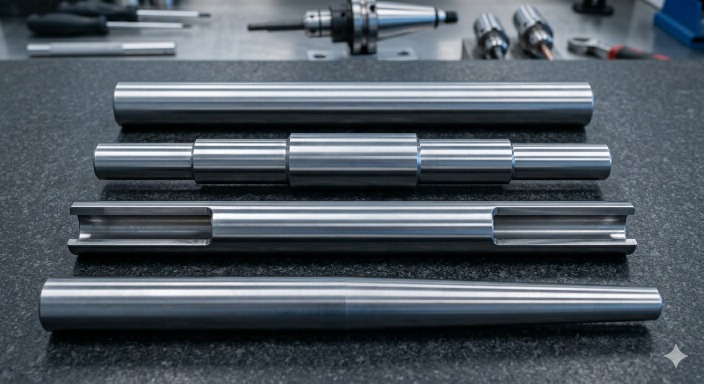
(AI generated) Different types of industrial shafts
A shaft doesn’t come out of a machine in one go. It moves through a sequence, and that sequence changes depending on how tight your tolerances are and how complex the geometry gets.
Typical Steps in the Shaft Manufacturing Process
Most shafts follow a similar path. Not identical, but close enough that you’ll recognize the pattern:
| Step | What actually happens | Why it matters |
|---|---|---|
| Material prep | Bar stock gets cut to length | Bad stock = bad part. Straightness and material quality show up later |
| Rough turning | First pass to remove bulk material | Sets the base geometry, but accuracy is still loose |
| Semi-finishing | Diameters get closer to final size | Reduces load for finishing tools |
| Feature machining | Grooves, keyways, threads, holes | This is where geometry complexity starts to affect cycle time |
| Heat treatment (if needed) | Hardening or stress relief | Changes material behavior completely |
| Finish turning / grinding | Final dimensions and surface finish | This is where tolerances are actually achieved |
| Inspection | Runout, diameter, surface finish checks | Catch problems before assembly does |
Here’s what people underestimate: once heat treatment is involved, you’re basically machining the part twice. Everything before heat treat is setup. Everything after is precision.
How Process Flow Changes by Shaft Geometry and Accuracy Requirements
This is where things stop being “standard.”
A simple straight shaft with loose tolerances? You can turn it, add features, and you’re done.
A stepped shaft with tight bearing fits? Now you’re controlling runout, surface finish, and transition radii. That usually means additional passes, better tooling, sometimes grinding.
Long, slender shafts change the process completely. You start dealing with deflection. That means slower feeds, support with tailstocks or steady rests, and sometimes splitting operations just to keep it straight.
High-precision shafts (like spindles) don’t rely on turning alone. They usually go through grinding because turning can’t consistently hit micron-level tolerances under real conditions.
So the process isn’t fixed. It bends around three things:
• geometry (simple vs stepped vs long/slender)
• material (soft vs hardened)
• tolerance (loose vs tight fits)
Ignore any one of those, and the process breaks down halfway through.
What Are the Different Shaft Shapes and Forms?
| Shape | Why use it? | The Practical Headache |
|---|---|---|
| Straight | Cheap and fast to turn. | Nothing to stop parts from sliding; you're stuck relying on set screws or collars. |
| Stepped | Creates shoulders to seat bearings and gears. | Sharp corners at the steps act as "perforations", if you don't radius them, the shaft snaps there. |
| Hollow | Cuts weight and handles high-speed vibration better. | Wall thickness has to be perfect. If it's too thin, the shaft collapses under the load of a pulley. |
| Tapered | Self-centering and easy to swap (like a mill spindle). | Half a degree of error in the machine setup ruins the fit. It’ll either wobble or seize up. |
Mechanical Features for Torque
| Feature | Best for... | The Trade-off |
|---|---|---|
| Keyway | Standard, low-cost torque transfer. | Keyway corners are common stress concentration points and should be designed with proper geometry and machining control. |
| Splines | High torque and heavy impact (axles/gearboxes). | Expensive to machine. If the tolerance is loose, the teeth will eventually hammer themselves to death. |
| Threads | Holding parts in place axially. | Never use these for torque. They’ll either tighten until the bolt snaps or unscrew and fly off. |
What Materials Are Commonly Used for Shaft Machining?
| Material | Shop Reality | Common Use |
|---|---|---|
| Carbon Steel | Cheap and easy to cut, but it rusts and wears out fast. | General-purpose rods and low-load drives. |
| Alloy Steel | Tough as hell and resists fatigue, but eats tools and needs heat treat. | Heavy-duty automotive and industrial power shafts. |
| Stainless | Doesn't rust, but it’s "gummy." It work-hardens and smears if your speeds are off. | Food, medical, and marine environments. |
| Aluminum | Lightweight and easy to turn, but under the same geometry it has lower stiffness and torque capacity than steel. | High-speed, low-load electronics or toys. |
| Brass | Corrodes less than steel and machines like butter, but it's too soft for load. | Small precision instruments and clockwork. |
What Are the Main Shaft Machining Methods?
Different operations exist for a reason. Each one solves a specific problem that another method can’t handle cleanly.
Turning, Milling, Drilling, Grinding, and Threading
| Method | What it actually does | Where it’s used on a shaft | What to watch |
|---|---|---|---|
| Turning | Shapes the outer diameter | Main body of the shaft | Deflection on long parts |
| Milling | Cuts flats, keyways, slots | Torque transfer features | Alignment with shaft axis |
| Drilling | Creates holes (axial or radial) | Oil passages, mounting holes | Chip evacuation in deep holes |
| Grinding | Brings size and finish into tight tolerance | Bearing seats, precision surfaces | Heat and burn risk |
| Threading | Adds threads for locking components | Ends or specific sections | Weakens local cross-section |
Turning handles most of the geometry. Everything else is supporting it.
Secondary Operations for Precision Shaft Features
This is where things get expensive.
After the main machining, you often need secondary work to hit functional requirements. That includes:
• grinding for bearing fits
• honing or lapping for ultra-smooth surfaces
• broaching or shaping for internal features
• balancing for high-speed shafts
These upgrades are what make the shaft actually work in assembly.
For example, a bearing seat might look fine after turning. But without grinding, you’ll get premature wear or vibration in operation.
Why Turning Is the Core Process in Shaft Machining
Almost everything starts on a lathe for a reason.
A shaft is rotational by nature. Turning matches that perfectly. You spin the part, hold a fixed tool, and control diameter, concentricity, and surface finish in one setup.
That’s efficient. More importantly, it’s stable.
Trying to machine a shaft primarily with milling would be slower, less accurate for round features, and harder to control.
But turning isn’t perfect.
Once parts get long, thin, or heavily featured, turning alone can’t maintain stability. That’s when you start adding supports, secondary ops, or even switching machines.
Still, if you strip the process down to its core, shaft machining is turning first, everything else second.
What Is CNC Shaft Machining?
(AI generated) Finished precision shaft being measured
CNC shaft machining is the controlled version of the same process. The difference is consistency.
Instead of relying on manual adjustments, the machine follows programmed paths, which keeps every part aligned with the same geometry and tolerances.
How CNC Technology Improves Shaft Machining Accuracy
In CNC shaft machining, repeatability is the real advantage.
Every pass is identical, so diameters, step locations, and transitions stay consistent across parts. That’s critical when you’re producing batches where even small variation leads to assembly issues.
You also get tighter control over cutting conditions, which helps maintain surface finish and reduces variation caused by tool behavior.
When CNC Shaft Machining Is the Best Choice
CNC becomes the right choice as soon as consistency and tolerance matter.
If you’re working with complex geometry, multiple features, or tight fits, CNC shaft machining keeps the process predictable. It also reduces scrap when the shaft manufacturing process involves multiple steps or secondary operations.
For simple shafts, manual methods can still work. But once you scale production or tighten tolerances, CNC is what keeps the process under control.
What Is Precision Shaft Machining?
Precision shaft machining is shaft machining where you stop thinking in “shape” and start working in measurable limits. You’re controlling tolerance, alignment, and surface behavior at the same time, because the shaft only works if all three stay inside a tight window.
Tolerance, Concentricity, and Surface Finish Requirements
| Parameter | What it means in precision shaft machining | Why it matters in real use |
|---|---|---|
| Tolerance | How close dimensions stay to the design value | A few microns off can cause bearing fit failure |
| Concentricity | How well all diameters share the same center axis | Misalignment leads to vibration and uneven wear |
| Surface finish | Smoothness of machined surface (Ra value) | Directly affects friction, heat, and fatigue life |
In precision shaft machining, you don’t treat these separately. They interact. A shaft can be within diameter tolerance but still fail if concentricity or surface finish is off.
That’s why precision shaft machining is really a control problem, not just a cutting process.
What Are the Challenges and Advanced Techniques in Long Shaft Machining?
Long shaft machining pushes the process away from geometry and into stability control. The longer the shaft, the more it behaves like a flexible beam instead of a rigid part.
Common Problems in Long Shaft Machining
| Problem | What actually happens | Result in machining |
|---|---|---|
| Deflection | Shaft bends under cutting force | Tapered diameters, loss of accuracy |
| Vibration | Tool and workpiece resonate | Poor surface finish, chatter marks |
| Thermal expansion | Heat changes shaft length during machining | Dimensional drift across the part |
| Tool pressure variation | Uneven load along long cuts | Inconsistent geometry along axis |
In shaft machining process planning, long shafts are where assumptions break first. You can’t treat them like short rigid parts.
Support, Stability, and Process Control Techniques
To control long shaft machining, you don’t increase force. You reduce instability.
Support methods like steady rests and tailstocks keep the shaft aligned and reduce bending during cutting. Tool engagement is also controlled to avoid sudden load spikes that trigger deflection.
Feed rates are often adjusted dynamically along the shaft length. Roughing and finishing are sometimes split into separate setups to reduce accumulated error.
In cnc shaft machining, simulation and toolpath control also help reduce vibration before the cut even starts.
The goal is simple: keep the shaft aligned while it’s being shaped, not correct it afterward.
Example Workflow: How Is a Stepped Shaft Machined?
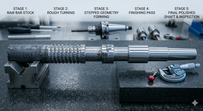
(AI generated) Stepped shaft manufacturing workflow showing progressive CNC machining
A stepped shaft looks simple, but the shaft manufacturing process behind it is layered. Each step builds on the previous one, and errors carry forward if not controlled early.
CNC Turning Steps for a Stepped Shaft
First, raw stock is cut and mounted. The initial turning pass establishes a reference diameter and ensures the part is running true on the axis.
Then rough turning removes excess material, creating the basic stepped geometry without worrying about final accuracy.
After that, semi-finishing brings each step closer to target dimensions while controlling stress and deflection.
Final turning defines the exact diameters and transitions between steps. If tolerances are tight, grinding is added for bearing seats or critical surfaces.
Throughout the process, alignment is constantly checked because any drift affects every subsequent step.
Critical Quality Checks During the Process
Quality control in precision shaft machining happens during production, not after.
Runout is checked after initial turning to confirm the axis is stable. Diameter measurements are taken after semi-finishing to ensure no drift is building up.
Surface finish is verified at final stages because it directly affects friction and wear performance. In some cases, concentricity is checked between steps to ensure alignment across the full shaft length.
If any of these drift early, the part doesn’t recover later. It gets corrected immediately or scrapped.
What Factors Affect Shaft Machining Quality?
Shaft machining quality doesn’t come from one setting. It comes from how material, tooling, and process variables interact during cutting.
Material, Tooling, and Cutting Parameters
Material sets the baseline. Harder steels increase tool wear and reduce process stability. Softer materials machine easier but may deform under load.
Tooling controls the cut. Tool geometry, edge sharpness, and coating directly affect chip formation and heat buildup. A slightly worn tool can still cut, but it quietly damages surface finish and accuracy.
Cutting parameters decide stability. Feed rate, spindle speed, and depth of cut need to stay balanced. Too aggressive increases deflection. Too conservative increases heat and rubbing.
In shaft machining, small changes in any of these variables show up immediately in diameter consistency and surface quality.
Runout, Surface Finish, and Dimensional Control
Runout is usually the first hidden issue. If the shaft axis is off, every feature references a wrong centerline. That error multiplies across steps.
Surface finish affects more than appearance. Rough surfaces increase friction and wear, especially in rotating assemblies like motor shafts or drive shafts.
Dimensional control ties everything together. Even if individual steps are within tolerance, stack-up error across features can still cause assembly issues.
That’s why precision shaft machining depends on controlling all three together, not separately.
What Drives the Cost of Shaft Machining
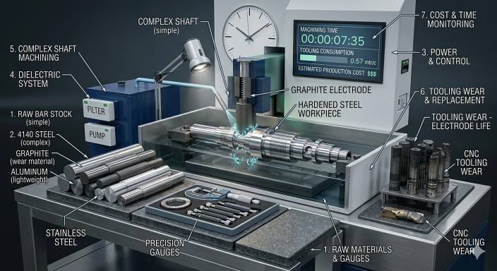
(AI generated) CNC shaft machining setup illustrating factors
Shaft machining cost isn’t linear. It increases sharply when geometry, material, or tolerance demands shift beyond standard turning.
Shaft Length and Diameter (L/D Ratio)
Long, thin shafts are harder to stabilize. Higher L/D ratios increase deflection risk, which forces slower feeds, extra supports, and sometimes multiple setups.
Short, thick shafts are easier to machine but may require more material removal, which still adds time.
Material Type and Heat Treatment
Free-machining steels reduce cost because they cut cleanly and extend tool life. Alloy steels and hardened materials increase machining time and tool wear.
Heat-treated shafts add another layer. Pre-hardening or post-machining heat treatment often requires finishing operations like grinding, which increases cost.
Tolerance and Surface Finish Requirements
Tighter tolerances increase inspection time and slow down machining. Achieving micron-level accuracy often requires additional finishing passes.
Surface finish requirements also matter. A rough industrial shaft is fast to produce. A bearing-quality surface requires slower feeds and sometimes grinding.
Machining Time and Setup Complexity
Complex shafts with multiple steps, keyways, or features require more tool changes and repositioning. Each setup adds time and potential error sources.
Long setup times often cost more than actual cutting time in precision shaft machining.
Batch Size and Production Strategy
Small batches increase per-part cost because setup time is spread over fewer units.
Larger batches reduce cost per shaft but require stable processes to maintain consistency across production runs.
What Are the Common Applications of Shaft Machining?
| Category | Application | Function / Requirement |
|---|---|---|
| Automotive | Drivetrain shafts | Torque transfer, vibration resistance |
| Aerospace | Rotating assemblies | Low weight, fatigue resistance |
| Industrial | Pumps, conveyors, gear systems | Continuous reliability, stable alignment |
| Power transmission | Long shafts | Energy transfer over distance, alignment control |
| Motor shafts | Electric motors | High concentricity, smooth rotation |
| Drive shafts | Vehicle and machinery systems | Torque transfer, cyclic load handling |
| Stepped shafts | Multi-diameter components | Positioning multiple assemblies along axis |
| Precision rotating parts | Spindles, high-speed shafts | Low runout, high surface finish, stability |
How to Optimize Shaft Design for Manufacturing?
Good shaft design reduces machining time, improves consistency, and lowers cost before the part ever reaches the machine.
Diameter Transitions, Tolerance Planning, and Feature Design
Sharp diameter changes create stress and machining difficulty. Smooth transitions with proper radii reduce tool load and improve fatigue life.
Tolerance planning should focus only on functional surfaces. Over-tolerancing non-critical features increases cost without improving performance.
Feature design matters too. Simple keyways and standard grooves machine faster than complex or custom geometries that require multiple setups.
How to Improve Manufacturability and Reduce Production Cost
You reduce cost by reducing operations, not by pushing faster cutting.
Avoid unnecessary tight tolerances. Standardize diameters where possible. Design features that align with turning operations instead of forcing milling or secondary setups.
The simpler the shaft geometry, the more stable the shaft machining process becomes, and the lower the overall production cost stays.
How to Choose a Shaft Machining Supplier
You don’t choose a shaft machining supplier based on price alone. You choose based on whether they can hold geometry, repeat it, and prove it.
Capabilities in Long Shaft and Precision Machining
Long shaft work exposes weak setups fast. If a shop cannot control deflection and vibration on long parts, you will see taper, chatter marks, and inconsistent diameter.
Precision shaft machining capability shows up in how they handle concentricity across multiple steps. Not just single operations, but full-length stability from roughing to finishing.
Equipment (CNC Turning, Grinding, Multi-axis)
CNC turning handles the core of shaft manufacturing. If a supplier lacks stable turning capacity, everything else falls apart.
Grinding becomes necessary when you need tight tolerance zones or bearing surfaces. It defines final accuracy.
Multi-axis machines matter when shafts include keyways, cross holes, or off-axis features. Without them, setups multiply and errors increase.
Tolerance and Inspection Capability
A supplier is only as good as their measurement system.
Dimensional control may require a combination of micrometers, dial indicators, runout measurement setups, and CMM inspection depending on the shaft geometry and tolerance requirements.
If they cannot show consistent inspection reports, you cannot trust batch repeatability.
Lead Time and Cost Considerations
Short lead time only matters if quality stays stable.
Fast machining with poor control increases scrap and rework. That pushes real cost higher than quoted price.
Stable suppliers balance setup time, machining time, and inspection without cutting corners on accuracy.
Need precision shafts without guesswork on cost or tolerance risk? Send your design to JLCCNC. We’ll help you move from concept to production with stable, repeatable machining.
Precision CNC Machining Service
Professional manufacturing, fast turnaround, and quality assurance.
FAQ about Shaft Machining
Q: What is shaft machining?
Shaft machining is the process of shaping rotating mechanical parts like shafts using turning, milling, grinding, and finishing operations.
Q: What is a shaft in mechanical engineering?
A shaft is a rotating mechanical component that transmits torque and motion between machine parts.
Q: How does a shaft work?
A shaft works by transferring rotational energy from a driving source to a driven component while maintaining alignment and load balance.
Q: What materials are commonly used for shaft machining?
Common materials include carbon steel, alloy steel, stainless steel, aluminum, and brass depending on strength and corrosion needs.
Q: What is the shaft machining process?
The shaft machining process includes turning, cutting features, heat treatment if required, and final grinding or finishing for precision.
Q: What is CNC shaft machining?
CNC shaft machining uses computer-controlled machines to produce shafts with high accuracy, repeatability, and controlled tolerances across production runs.
Popular Articles
• Cutting with Precision: A Comprehensive Guide to CNC Water Jet Technology
• CNC Coolant Explained: Types, Maintenance & Safety
• Rake Angle in Machining: Machinists’ Guide to Perfect Cuts
• What Steps Are Taken To Minimize Waste In CNC Machining Processes?
• How EDM Wire Cutting Works: Complete Guide to Precision CNC Wire Cutting
Keep Learning
Chatter in Machining: Causes, Effects, and How to Reduce It
CNC milling operation producing visible chatter marks on an aluminum workpiece Quick Chatter Diagnosis Checklist Symptom Most Likely Cause First Action High-pitched squeal Regenerative chatter Change spindle speed ±15% Chatter only in deep pockets Excessive tool overhang Shorten tool Chatter on thin walls Low workpiece rigidity Improve fixturing Chatter after tool replacement Runout / holder issue Check tool holder Chatter only during finishing DOC too small / rubbing Increase feed or adjust speed It ......
What Is Tool Offset in CNC? Types, Setup & Best Practices
CNC tool offset setup with measurement overlay Key Takeaways CNC offsets connect programmed intent with actual cutter position. Length data guides Z-axis depth control. Radius data protects part size during contour milling. Geometry values define the cutter's measured baseline. Wear values support fine correction during production. Verified data lowers scrap risk before full machining. Good offset habits protect tools, fixtures, and parts. In the context of CNC machining , tool offset is the quiet set......
Trochoidal Milling: Complete Guide to High-Efficiency CNC Machining
Key Takeaways Trochoidal milling combines circular cutter motion with continuous forward feed. The cutter normally engages 5 to 20% of its diameter instead of making a full-width cut. A smaller engagement angle limits force changes during slotting and pocket roughing. Low radial engagement often allows greater axial depths of cut than conventional slot milling. CAM software calculates the circular path automatically from the selected machining parameters. This strategy is widely applied to titanium, s......
What Is Die Casting? Process, Materials, and Applications
Key Takeaways Die casting is a metal casting process that forces molten metal into a reusable steel mold under high pressure, producing parts with tight tolerances and good surface finish at high volume. Aluminum die casting is the most common form by far, thanks to its combination of light weight, decent strength, and good corrosion resistance. The die casting process runs through mold preparation, injection, cooling, and ejection in a cycle that can repeat every few seconds to minutes depending on p......
First Angle vs Third Angle: Understanding Orthographic Projection Methods
Key Takeaways Orthographic projection is the system that lets a 3D part be represented through multiple 2D views, front, top, side, and so on. First angle projection and third angle projection are the two standard methods for arranging those views, and they place views in opposite positions relative to the object. First angle projection is the ISO standard used across most of Europe, India, China, Russia, and many other countries following ISO standards Third angle projection is the standard in the Un......
Micro EDM Machining: Capabilities, Materials, and Applications for Precision Components
Key Takeaways About Micro EDM Machining Only electrically conductive materials can be machined. Hole diameters can reach below 50 μm on specialized equipment. The process produces almost no mechanical cutting force, making it suitable for thin or delicate features. Surface integrity still requires attention because recast layers and heat-affected zones may remain after machining. Micro EDM is often combined with CNC machining, with milling producing the main geometry before EDM finishes critical micro......