Undercut Machining in CNC: Tool Access, Feature Types, and Manufacturing Challenges
15 min
- What Is an Undercut in Machining?
- Why Undercuts Are Difficult to Machine
- Common Types of Undercut Features in CNC Machining
- CNC Tool Access and Machining Stability for Undercuts
- Designing Undercuts for CNC Manufacturability
- Common Machining Failures in Undercut Features
- How CNC Machine Capability Influences Undercut Machining
- Conclusion About Undercut Machining
- FAQ About Undercut Machining
Key Takeaways About Undercut Machining
- Undercut machining creates features that standard tools cannot reach from a straight cutting direction.
- These features are commonly used for clearance, assembly locking, mating surfaces, and hidden geometry.
- Tool access becomes the main limitation because the cutting area sits behind a wall, shoulder, or internal feature.
- Undercuts often require lollipop cutters, T-slot tools, keyseat cutters, and custom tooling.
- Longer tool reach reduces rigidity and can affect dimensional consistency during machining.
- Hidden cutting areas make chip evacuation and visual inspection more difficult.
- Multi-axis machining is often used to improve tool approach and reduce setup limitations.
- Undercut features usually need additional review during DFM because geometry directly affects machinability.
- Small design changes in radius, depth, or access space can simplify machining significantly.
- Undercut machining generally takes more setup planning than standard milling features.
Undercut features appear in parts where standard tool movement cannot create the required geometry. The cutting area sits behind a wall, under a shoulder, and inside a restricted section that blocks direct tool access. These features are common in mechanical assemblies, mating interfaces, locking designs, and specialized component geometry.
Unlike standard pockets or profiles, undercuts are usually limited by tool entry rather than toolpath generation. A feature may look simple on the CAD model, but become difficult once machining starts because cutter reach, clearance space, and tool movement become restricted.
In production, undercut features often require special tooling and additional setup planning. Tool stability becomes more sensitive because cutting usually happens away from the spindle with less support. Feature depth, corner shape, and access direction also affect whether the part can be machined consistently.
This article explains undercut machining from a CNC manufacturing view, including feature types, tooling methods, access limitations, and the practical challenges involved in machining hidden geometry.
What Is an Undercut in Machining?
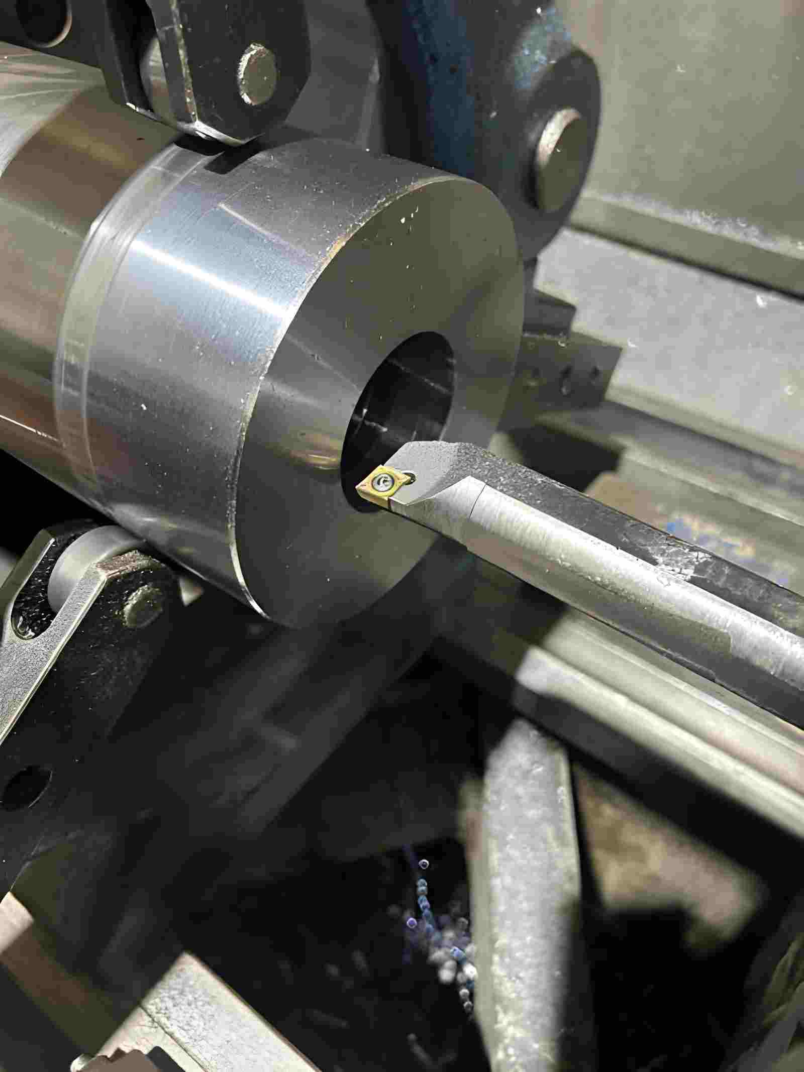
Undercut machining on a CNC lathe using specialty tooling for internal recessed features. Source: iStock
Undercut features are usually created in areas where the cutting tool cannot approach directly from a normal machining direction. In CNC machining, these hidden or blocked geometries need additional tool access planning because standard milling tools cannot reach behind walls, shoulders, or enclosed areas.
Why Undercuts Are Used in Mechanical Components
Undercuts are added when a part needs geometry that cannot be produced through standard cutting access. These features are commonly used to create assembly clearance, locking areas, mating surfaces, and tool relief zones. In mechanical parts, they also help components seat correctly during assembly, where standard profiles cannot provide enough clearance.
In threaded parts, undercuts are often placed near thread ends to create tool exit space. In mating assemblies, they allow components to fit without interference at corners and transitions. Some undercut relief features are also used to reduce stress concentration near sharp geometry transitions.
Difference Between Undercuts, Grooves, and Standard Milling Features
Undercuts, grooves, and standard features remove material differently because tool access changes across each geometry. The biggest difference is not the feature shape but how the cutter reaches the area.
| Feature | Tool Access Direction | Geometry Position | Typical Tool | Cutting Behavior | Main Machining Challenge |
|---|---|---|---|---|---|
| Undercut | Restricted or hidden access | Behind shoulders or enclosed areas | Lollipop cutter, T-slot cutter | Cutter engages in partially blocked geometry with limited visibility | Tool reach, rigidity, and chip evacuation |
| Groove | Open linear access | Internal, external, or face surfaces | Grooving insert, narrow cutter | Continuous cutting along an exposed path | Chip control and dimensional consistency |
| Standard milling feature | Direct top or side access | Open surfaces and accessible geometry | End mill, face mill | Standard cutting with open tool movement | General toolpath efficiency and surface finish |
Why Undercuts Are Difficult to Machine
Undercut features create machining conditions that differ from standard profiles and pockets. The cutting area sits in a restricted location, so machining difficulty comes from access limitations, tool behavior, and reduced visibility during production.
Machining Stability in Recessed Features
Undercut tools remove material away from the main spindle support area. Cutting forces act farther from the tool holder, which changes how the tool reacts during engagement. In deeper recessed areas, small tool movement can leave wall marks or create variation on feature edges.
Chip Evacuation and Heat Accumulation
Undercuts often trap chips because the cutting zone sits inside a partially enclosed area. Chips have fewer paths to leave the feature, especially in deeper internal sections. As chips stay around the cutting edge longer, cutting temperature rises and surface condition becomes harder to maintain.
Hidden Geometry and Inspection Challenges
Many undercut features cannot be viewed directly after machining. Internal corners, backside cuts, and recessed profiles may require section measurement tools, probes, or CMM inspection. In production, feature verification can take longer because visual checks alone cannot confirm dimensional accuracy.

Precision CNC Machining Service
Professional manufacturing, fast turnaround, and quality assurance.
Common Types of Undercut Features in CNC Machining
Undercut features differ by geometry, cutter approach direction, and access space around the feature. Machining strategy changes based on how much clearance exists around the cutting area and how the tool reaches the feature. Common types of undercut in machining include thread reliefs, bore undercuts, shaft reliefs, T-slot undercuts, and dovetail features.
Internal Relief and Bore Undercuts
Internal relief undercuts add clearance inside bore transitions and recessed internal sections. Bore diameter and feature depth usually limit cutter size selection. A smaller access space increases tool reach requirements and reduces rigidity during cutting.
External Relief and Shaft Undercuts
External shaft undercuts create a transition area between stepped diameters and adjacent surfaces. These features support part seating and remove interference near the shoulders. External access allows shorter tools and more stable cutting conditions.
Thread Relief and Runout Undercuts
Thread relief undercuts create a termination area at thread ends. The feature provides space for clean thread completion and cutter exit movement. Width and depth are usually controlled by thread size and tool geometry.
Standardized Undercuts and Relief Features
Standard undercuts follow defined dimensional ranges used across repeated manufacturing work. Standard geometry simplifies tooling selection and reduces unnecessary feature variation between designs. Many thread relief and shaft undercut geometries follow DIN and ISO machining standards to maintain tooling compatibility and assembly clearance consistency.
T-Slot and Dovetail Undercuts
T-slot and dovetail undercuts contain hidden cutting areas below an upper surface profile. These features need dedicated tooling because material removal happens beneath the visible opening. Tool angle and cutter reach become major setup considerations.
Table 01: Undercut Feature Comparison
| Feature Type | Geometry Form | Tool Access Condition | Geometry Limitation | Typical Tool | Main Machining Concern |
|---|---|---|---|---|---|
| Internal relief undercut | Recessed internal transition | Access is limited by bore size | Diameter and depth restrictions | Internal undercut tool | Tool reach and rigidity |
| External shaft undercut | Diameter transition feature | Open side access | Shoulder spacing | Relief turning tool | Dimensional consistency |
| Thread relief undercut | Narrow groove near the thread end | Localized cutting access | Thread size relationship | Grooving insert | Thread completion accuracy |
| Standard relief feature | Defined relief geometry | Standard cutter approach | Dimensional standard limits | Relief tool | Repeatability |
| T-slot undercut | Hidden lower profile | Access through the top opening | Neck width and cutter reach | T-slot cutter | Chip evacuation |
| Dovetail undercut | Angled hidden profile | Side cutting approach | Cutter angle restriction | Dovetail cutter | Tool stability |
CNC Tool Access and Machining Stability for Undercuts
Undercut features place more limits on the tool than standard pockets or profiles. The cutter often works away from open cutting space, so reach, support, and access conditions directly affect machining behavior.
Internal Grooving Tools and Specialty Cutters
- Standard end mills cannot reach many undercut profiles because the cutting area sits below or behind the surrounding geometry.
- Lollipop cutters, T-slot tools, and dovetail cutters are selected based on feature shape and available access space.
- A cutter may fit the feature diameter on CAD but still fail once holder clearance is considered during spindle movement.
Tool Reach, Overhang, and Accessibility Limits
- Deep undercuts usually require longer tool reach to access the cutting area behind the feature.
- As the overhang increases, the tool becomes less rigid and reacts more to cutting force.
- Limited clearance around the feature also restricts spindle movement and cutter approach direction.
Tool Deflection, Vibration, and Chatter
- Cutting force acts farther from the tool holder during undercut machining, which increases sensitivity to movement.
- Small tool deflection can leave size variation on recessed walls and hidden surfaces.
- Vibration becomes more noticeable in longer tools because cutter support decreases with reach.
Chip Evacuation and Coolant Access
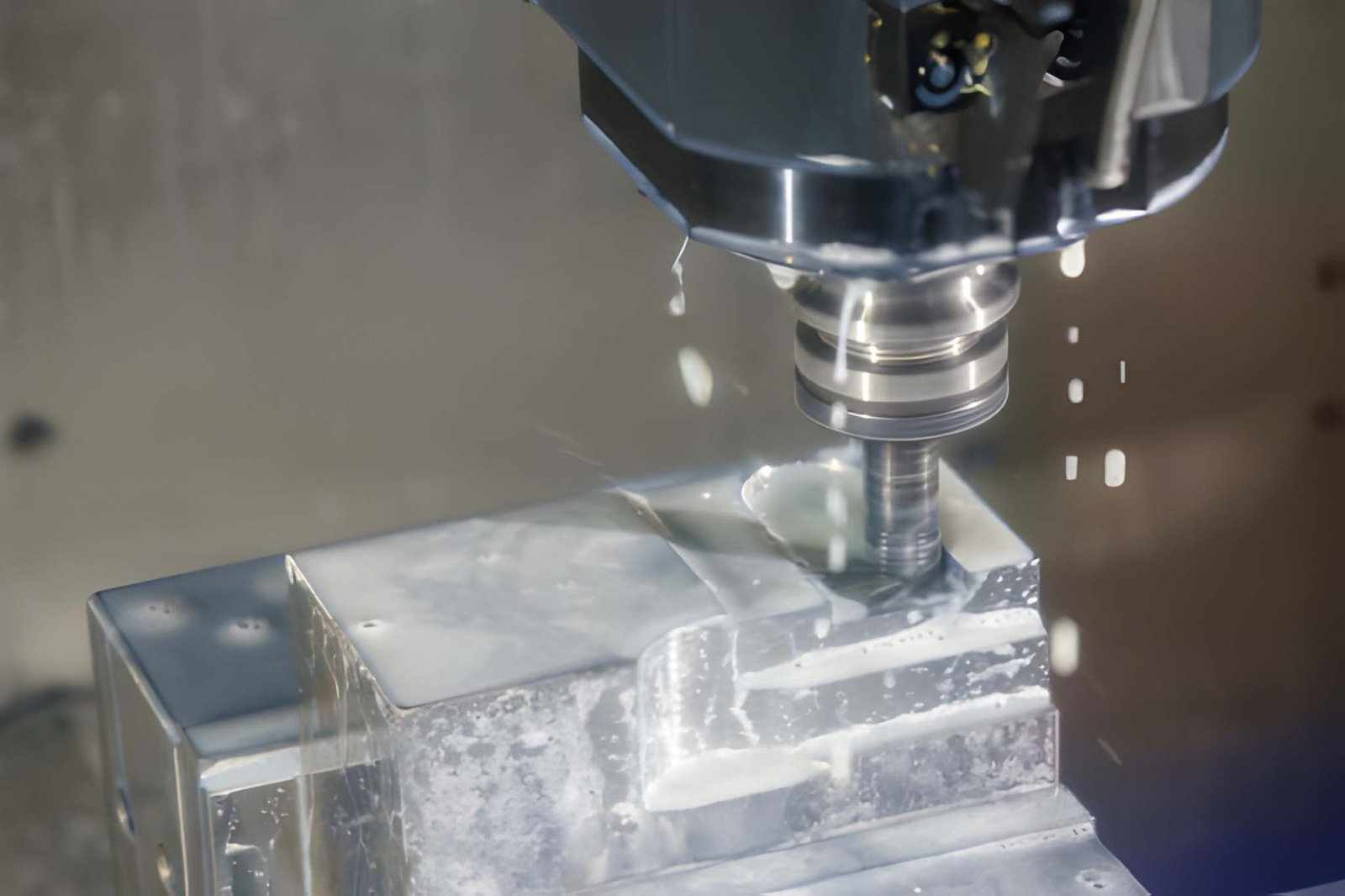
CNC milling machine cutting undercut areas in mold parts with coolant flow during machining. Source: iStock
- Undercuts create partially enclosed cutting areas with limited space for chip movement.
- Chips can remain inside the feature longer and interfere with the next cutting pass.
- Coolant access also becomes more restricted because the cutting edge sits inside a hidden area.
Multi-Axis Machining for Complex Undercuts
- Multi-axis machines allow the spindle to approach the feature from different angles.
- Better tool positioning reduces the need for excessive tool reach during machining.
- Complex undercuts can often be machined in fewer setups with improved cutter access.
Designing Undercuts for CNC Manufacturability
Undercut design affects tool selection, machining setup, and production stability. Small changes in geometry often decide whether a feature runs in a simple setup or needs special tooling and extra operations.
Designing Around Tool Accessibility
Undercut features need a clear path for tool entry and exit. If surrounding walls or shoulders block the cutter, longer reach tools or special cutters become necessary. Designs that leave direct access reduce setup changes and keep machining more stable during production.
Radius, Width, and Depth Design Considerations
Small internal radii usually force smaller cutter sizes, and that reduces rigidity during cutting. Narrow grooves also increase tool pressure because chip space becomes limited. Deeper undercuts increase tool reach, which can lead to deflection and variation in feature size during long cuts.
Tolerance and Inspection Considerations
Tighter tolerances inside undercuts increase machining time because tool movement needs more control at every pass. Some internal features cannot be checked with simple gauges, so probing or CMM inspection is often required. In production, only functional surfaces should carry tight tolerance control.
Material Effects on Undercut Machining
Aluminum generally machines more easily in undercut features because chip flow remains smoother and cutting resistance stays lower. Stainless steel increases tool load and heat inside confined spaces, which affects tool life and surface condition. Harder alloys demand slower cutting speeds because tool stress rises quickly in restricted geometry.
CNC Turning vs Milling for Undercuts
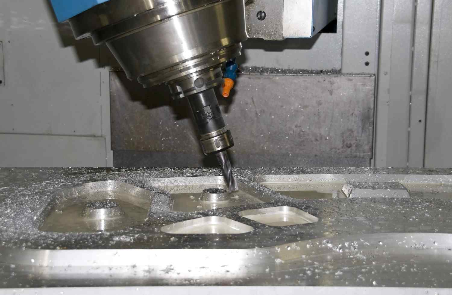
A CNC milling tool is machining the undercut feature on a metal part. Source: Depositphotos
CNC turning handles shaft undercuts and thread reliefs more efficiently because tool movement follows a stable rotational path. Milling becomes necessary for side features or hidden geometries that require angled tool access. Process choice usually depends on how open or blocked the feature is.
Machining Sequence and Process Planning
Undercuts are usually cut after major stock removal, so the tool can reach the feature without obstruction. Rough machining first creates access space and reduces tool reach issues in later operations. Proper sequence also helps prevent finished surfaces from blocking cutter movement during final passes.
For production CNC parts with recessed or hidden features, early DFM review often helps avoid unnecessary tooling complexity and unstable machining conditions. JLCCNC reviews undercut accessibility, cutter clearance, and machining stability before production to reduce setup risks on complex CNC parts.
Common Machining Failures in Undercut Features
Undercut machining failures usually come from limited access and unstable cutting conditions. Because the tool works inside restricted geometry, small variations in setup or cutting load directly affect final feature quality.
In production environments, unstable undercut machining can increase setup verification time, shorten tool life, and raise inspection cost due to limited feature accessibility.
Inconsistent Undercut Dimensions
Undercut sizes can shift when tool deflection changes during cutting. Long reach tools bend slightly under load, which affects width and depth control. Small changes in chip load or tool wear also show up faster in these narrow features compared to open surfaces.
Burrs and Surface Defects in Hidden Features
Burr formation is common at undercut edges because the chip exit space is limited. Chips rub against the surface before leaving the cutting zone, which leaves sharp edges or rough transitions. Internal areas often retain burrs because post-processing access is restricted.
Tool Breakage in Deep or Narrow Undercuts
Deep undercuts increase tool overhang, which reduces rigidity during cutting. When cutting load spikes due to chip buildup or sudden engagement, small cutters can fail quickly. Breakage risk increases in stainless steel and hard alloys because cutting forces remain high in confined spaces.
Distortion in Thin-Wall or Complex Components
Thin sections near undercuts can move during machining due to localized cutting stress. Removing material close to unsupported walls reduces stiffness, which leads to slight bending or shape shift. This effect becomes more noticeable in long or hollow parts with multiple recessed features.
How CNC Machine Capability Influences Undercut Machining
Undercut features depend on how stable the machine stays during cutting and how freely the tool can move around the part. Limited space inside the feature makes machine rigidity and axis movement more important than standard machining work.
3-Axis vs 5-Axis Undercut Capability
- 3-axis milling setups handle simple undercuts found in parts like external shaft reliefs, basic thread relief grooves, and open-edge clearance cuts on brackets.
- 5-axis machines rotate the part or tool, which helps reach hidden features in components like turbine housings, aerospace brackets, and complex medical device bodies.
- Extra axis movement reduces repositioning and keeps the feature aligned in one setup.
Tool Orientation and Reach Control
- Tool angle controls how the cutter meets the surface, such as straight entry, side approach, or tilted engagement during undercut cutting.
- Incorrect angle selection forces the tool to cut at full reach in angled or backward directions, which reduces support and increases deflection risk.
- Proper orientation keeps the cutting direction aligned with tool strength, which improves stability in side cuts, bottom cuts, and reverse-access undercut areas.
Holder Clearance and Interference
- Tool holders need space around the cut, even in tight undercut zones.
- Limited holder clearance around the feature increases interference risk during undercut machining, especially in deep internal sections.
- Compact setups reduce the chance of interference in deep cuts.
Coolant Delivery in Hidden Features
- Coolant flow becomes weaker once the cutting zone moves inside a closed area.
- Heat builds up faster because chips and fluid cannot clear freely.
- Directed coolant improves chip movement and keeps cutting stable.
Conclusion About Undercut Machining
Undercut machining is defined more by tool access than by nominal dimensions on the drawing. Features that sit behind walls or inside recessed zones depend on whether the cutter can physically reach and stay stable during cutting.
In production, the machining behavior inside the undercuts decides the final accuracy. Tool reach, support length, and clearance space affect how the cutter holds size during engagement, especially in deeper or hidden areas.
Undercut features are often manufacturable, but not always with the first geometry drafted in CAD. Early DFM review usually focuses on tool access, cutter stability, and inspection feasibility before machining begins.
For CNC parts with recessed or restricted-access features, JLCCNC reviews undercut geometry during quoting to help identify tooling limitations and machining risks before production.
Precision CNC Machining Service
Professional manufacturing, fast turnaround, and quality assurance.
FAQ About Undercut Machining
Q: What is an undercut in machining?
An undercut is a recessed feature that sits behind a surface or shoulder, and standard straight cutting tools cannot reach it directly. It is used for clearance, locking, and hidden fit functions in assemblies.
Q: What is the difference between a groove and an undercut?
A groove sits in an open cutting path with direct tool access, while an undercut sits in a hidden area behind geometry. Grooves allow continuous tool entry, while undercuts need special tool shapes or angled access.
Q: Which CNC tools are used for internal undercuts?
Internal undercuts use lollipop cutters, T-slot cutters, and keyseat-style tools. Tool choice depends on bore size, depth, and how much side access is available inside the feature.
Q: Why are undercuts difficult to machine?
Undercuts restrict tool movement and reduce cutting support. Tool reach increases, chip flow becomes limited, and cutting stability drops inside the confined space.
Q: When is 5-axis machining needed for undercuts?
5-axis machining is used when tool access is blocked in a straight path. Rotating the tool or part allows access to hidden faces, angled undercuts, and complex internal features without multiple setups.
Q: Are undercuts expensive to machine?
Undercuts usually increase machining cost because they need special tooling, slower cutting conditions, and more setup planning. Cost also increases when inspection and finishing steps become more complex.
Q: Which materials are easiest to undercut-machine?
Aluminum is generally easier due to smooth cutting and lower tool load. Mild steel also performs well. Stainless steel and hardened materials increase difficulty because they create higher cutting resistance and tool wear.
Popular Articles
• Cutting with Precision: A Comprehensive Guide to CNC Water Jet Technology
• CNC Coolant Explained: Types, Maintenance & Safety
• Rake Angle in Machining: Machinists’ Guide to Perfect Cuts
• What Steps Are Taken To Minimize Waste In CNC Machining Processes?
• How EDM Wire Cutting Works: Complete Guide to Precision CNC Wire Cutting
Keep Learning
Chatter in Machining: Causes, Effects, and How to Reduce It
CNC milling operation producing visible chatter marks on an aluminum workpiece Quick Chatter Diagnosis Checklist Symptom Most Likely Cause First Action High-pitched squeal Regenerative chatter Change spindle speed ±15% Chatter only in deep pockets Excessive tool overhang Shorten tool Chatter on thin walls Low workpiece rigidity Improve fixturing Chatter after tool replacement Runout / holder issue Check tool holder Chatter only during finishing DOC too small / rubbing Increase feed or adjust speed It ......
What Is Tool Offset in CNC? Types, Setup & Best Practices
CNC tool offset setup with measurement overlay Key Takeaways CNC offsets connect programmed intent with actual cutter position. Length data guides Z-axis depth control. Radius data protects part size during contour milling. Geometry values define the cutter's measured baseline. Wear values support fine correction during production. Verified data lowers scrap risk before full machining. Good offset habits protect tools, fixtures, and parts. In the context of CNC machining , tool offset is the quiet set......
Trochoidal Milling: Complete Guide to High-Efficiency CNC Machining
Key Takeaways Trochoidal milling combines circular cutter motion with continuous forward feed. The cutter normally engages 5 to 20% of its diameter instead of making a full-width cut. A smaller engagement angle limits force changes during slotting and pocket roughing. Low radial engagement often allows greater axial depths of cut than conventional slot milling. CAM software calculates the circular path automatically from the selected machining parameters. This strategy is widely applied to titanium, s......
What Is Die Casting? Process, Materials, and Applications
Key Takeaways Die casting is a metal casting process that forces molten metal into a reusable steel mold under high pressure, producing parts with tight tolerances and good surface finish at high volume. Aluminum die casting is the most common form by far, thanks to its combination of light weight, decent strength, and good corrosion resistance. The die casting process runs through mold preparation, injection, cooling, and ejection in a cycle that can repeat every few seconds to minutes depending on p......
First Angle vs Third Angle: Understanding Orthographic Projection Methods
Key Takeaways Orthographic projection is the system that lets a 3D part be represented through multiple 2D views, front, top, side, and so on. First angle projection and third angle projection are the two standard methods for arranging those views, and they place views in opposite positions relative to the object. First angle projection is the ISO standard used across most of Europe, India, China, Russia, and many other countries following ISO standards Third angle projection is the standard in the Un......
Micro EDM Machining: Capabilities, Materials, and Applications for Precision Components
Key Takeaways About Micro EDM Machining Only electrically conductive materials can be machined. Hole diameters can reach below 50 μm on specialized equipment. The process produces almost no mechanical cutting force, making it suitable for thin or delicate features. Surface integrity still requires attention because recast layers and heat-affected zones may remain after machining. Micro EDM is often combined with CNC machining, with milling producing the main geometry before EDM finishes critical micro......