Die Cutter Systems in Manufacturing: Structure, Process Engineering, Selection Logic & Industrial Applications
12 min
- What Is a Die Cutter? Mechanical Structure & Working Principle
- Die Cutter Selection Engineering Logic
- How Die Cutters Are Manufactured
- Die Cutter Failure Mechanisms
- Die Cutting vs Laser Cutting vs Waterjet
- Die Cutter Maintenance & Tool Life Engineering
- Industrial Applications
- Custom Die Cutter Manufacturing Strategy
- 9. FAQ About Die Cutter
Have you ever wondered why your die cutters wear out 2x faster than the supplier promised, or leave unsightly burrs on every part you produce? In my 12 years working in precision tooling procurement and manufacturing engineering, I’ve seen far too many teams skip over the core engineering principles of die cutters, leading to costly production delays and unexpected waste. This guide breaks down everything you need to know about cut die cutter systems, from their core mechanical structure to failure prevention, to help you make smarter procurement and production decisions.
What Is a Die Cutter? Mechanical Structure & Working Principle
Core engineering definition
In simple terms, a die cutter is a tool used to cut identical shapes from sheet materials in industrial production. Unlike general “cutting tools”, die cutters operate under:
- controlled shear failure (not melting or abrasion)
- fixed geometry cutting interfaces
- repeatable force distribution systems
Mechanical structure of die cutting systems
A typical industrial die cutter consists of:
- cutting edge (hardened steel or carbide)
- die base (tool steel or alloy base plate)
- support structure (press bed / rotary cylinder)
- alignment system (guide pins / CNC fixture alignment)
Working principle
Material failure occurs when: applied shear stress > material shear strength
Key variables that impact cut quality include:
- edge sharpness radius
- material yield strength
- cutting velocity
- support rigidity
Major industrial die cutter types
- Flatbed die cutter: Applies vertical press force, delivers high precision for sheet materials, ideal for low to medium volume production runs.
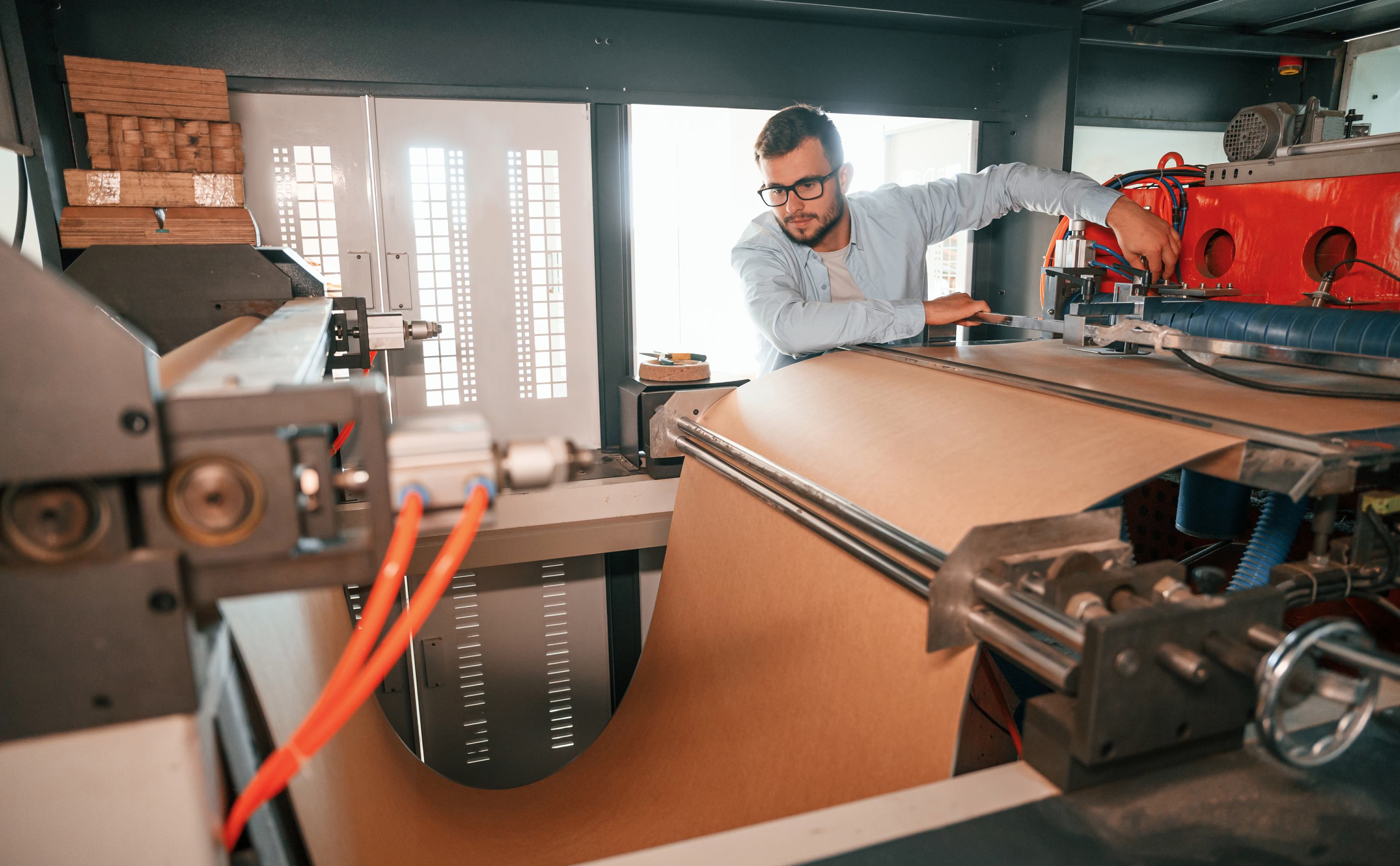
- Rotary die cutter: Designed for continuous roll-to-roll cutting, the industry standard for high-volume packaging production.
- CNC machined die tooling (prototype / low volume): CNC machining is used for rough shaping, while EDM is responsible for precision edge formation and complex internal geometries in industrial die tooling systems. For teams looking for fast prototype die tooling for design testing, vendors like JLCCNC offer CNC machined cut die cutter options with turnaround as fast as 3 days, so you can validate your design without waiting weeks for traditional tooling.

Precision CNC Machining Service
Professional manufacturing, fast turnaround, and quality assurance.
Die Cutter Selection Engineering Logic
Picking the right die cutter isn’t just about choosing the cheapest steel option. Selection must follow a 4-layer engineering model to avoid costly failures:
Layer 1: Material failure behavior
Different substrates fail differently under shear stress:
- brittle fracture (plastics like PMMA, glass fiber composites)
- ductile shear (aluminum, copper, soft steel)
- fiber tearing (paper, cardboard, natural fiber composites)
Die geometry must match the material’s failure mode to avoid cracking, delamination, or burrs.
Layer 2: Tool edge geometry design
Three key parameters determine cut quality and tool life:
- edge radius (critical for burr control, smaller radius for thinner materials)
- rake angle (affects cutting force, steeper angles for softer materials)
- clearance angle (prevents secondary friction between the tool and cut part)Incorrect geometry causes burr formation, delamination, and accelerated tool wear, often cutting tool life by 50% or more in high volume runs.
Layer 3: Load and force requirement
Total cutting force depends on three factors:
- material shear strength
- material thickness
- total cutting perimeter length
Undersized tooling leads to edge collapse, dimensional drift, and even press overload failure that can damage your production equipment.
Layer 4: Production volume strategy
Match your die type to your expected production volume to save costs without sacrificing quality:
- prototype → CNC machined die cutter
- medium volume → hybrid CNC + EDM tooling
- mass production → hardened stamping die system
If you’re still unsure which die type fits your project’s volume and tolerance needs, JLCCNC’s engineering support team can help you map your requirements to the right manufacturing process, with instant quotes available as soon as you share your design files.
Precision CNC Machining Service
Professional manufacturing, fast turnaround, and quality assurance.
Common engineering selection failures
I’ve seen these mistakes happen dozens of times:
- using rotary die for brittle plastics → consistent part cracking
- using flatbed die for high-speed production → throughput bottleneck that cuts output by 30%
- ignoring tool wear rate → tolerance drift over batch production that leads to 10%+ scrap rates
How Die Cutters Are Manufactured
There’s a common misconception that die cutters are purely CNC machined products. That’s not true for industrial-grade tooling. Industrial production uses a 5-step process that combines multiple precision manufacturing methods:
Step 1: CNC rough machining
Primary purpose is to remove bulk material, establish the base geometry baseline, and pre-form the tool structure. Limitation: CNC machining alone cannot achieve the sharp edge precision required for industrial die cutting, so it’s only used for the initial shaping phase.
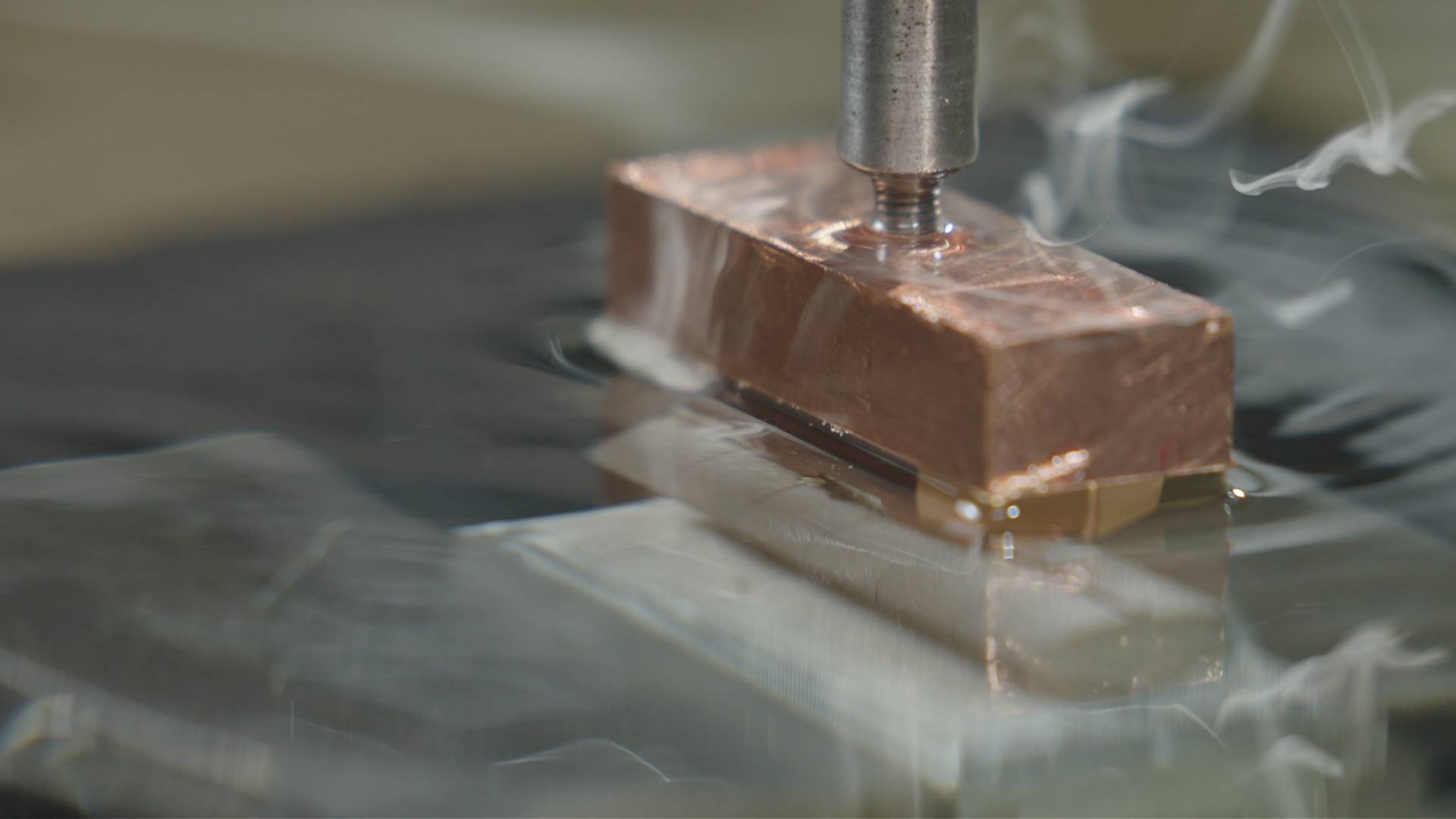
Step 2: EDM precision shaping
Electrical discharge machining is used for sharp internal corners, micro-tolerance cutting edges, and complex die profiles that CNC machining cannot produce. EDM is critical because it applies no mechanical stress to the tool material, delivering extremely high dimensional accuracy within ±0.001mm in most cases.
Step 3: Heat treatment process
This step increases the tool’s hardness (typically to HRC 55–65), improves wear resistance, and stabilizes the steel’s microstructure to prevent deformation during use. If heat treatment is miscontrolled, you’ll end up with overly brittle edges that chip easily, or soft edges that wear out after a few hundred cycles..
Step 4: Surface coating (optional but common)
Most high-volume industrial dies get a surface coating to extend service life:
- TiN (Titanium Nitride): Low cost, good wear resistance for general use
- DLC (Diamond-like Carbon): Low friction, ideal for cutting plastic and composite materials
- CrN (Chromium Nitride): High corrosion resistance, used for cutting food packaging materials
Coatings can extend tool life by 2–3x with minimal added cost.
Step 5: Final inspection
Every industrial die should go through rigorous testing before shipping, including edge sharpness measurement, dimensional tolerance verification, load simulation testing, and wear simulation validation. In my experience, working with a supplier that performs full load and wear simulation testing before shipping, like JLCCNC, cuts your risk of unexpected die failure in production by more than 60%.
Die Cutter Failure Mechanisms
This section is what most generic SEO articles completely miss, but it’s the key to reducing unplanned downtime. There are 5 common failure modes for cut die cutters:
Failure Mode 1: Edge wear degradation
Caused by abrasive materials, insufficient tool hardness, or high cycle stamping. It results in increased cutting force, burr formation, and dimensional drift over time. This is the most common failure mode, accounting for 70% of die replacements in high-volume production.
Failure Mode 2: Edge chipping
Occurs when tool hardness is too high (leading to brittle fracture), there are sudden impact loads during production, or the die is misaligned in the press system. Chipping usually happens without warning, so regular inspection is critical for high-volume lines.
Failure Mode 3: Plastic deformation of cutting edge
Occurs under excessive load, insufficient heat treatment, or poor base material selection. It results in permanent geometry change and progressive tolerance drift that gets worse with every cut. One automotive client I worked with last year wasted $20k in production downtime because they used a low-cost die without proper heat treatment, leading to edge deformation after just 200 cycles.
Failure Mode 4: Burr formation
Root causes include edge dulling that increases the edge radius, incorrect clearance angle between the die and cutting plate, or a mismatch between the material and die geometry that leads to tearing instead of clean shear. Burrs can add hours of secondary finishing work to your production process, so it’s always cheaper to fix the die issue than to remove burrs later.
Failure Mode 5: Fatigue failure
Long-term cyclic loading leads to micro-crack propagation along the cutting edge, eventually causing edge fracture and sudden total tool failure. Fatigue failure is most common in mass production dies that run 24/7 for months at a time.
Die Cutting vs Laser Cutting vs Waterjet
The fundamental difference between these three cutting processes is their material failure mechanism, which determines their best use cases:
| Method | Mechanism | Heat affected zone | Precision | Best for |
|---|---|---|---|---|
| Die cutting | mechanical shear failure | none | high for high volume runs | High volume production of identical parts |
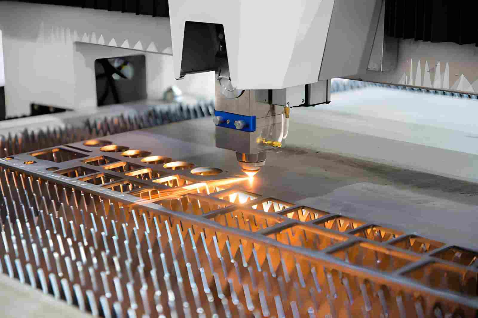
| Laser cutting | thermal vaporization | present | high for sheet metals | Prototyping, low volume custom parts |
| Waterjet | abrasive erosion | none | moderate-high | Thick materials, heat-sensitive composites |
Engineering selection logic
- Use die cutting when you have high volume production, repeatable geometry requirements, and low per-part cost is critical.
- Use laser cutting when you’re doing prototyping, frequent design iteration, and want to avoid upfront tooling costs.
- Use water jet when you’re cutting heat-sensitive materials, thick materials over 10mm, or composite structures that can’t be cut with thermal methods.
Die Cutter Maintenance & Tool Life Engineering
Tool life is not linear, it follows a 3-stage wear progression model:
- Initial stable phase: Minimal wear, consistent cut quality for the first 20–30% of the tool’s life
- Gradual edge dulling phase: Slow, predictable wear that can be mitigated with regular maintenance
- Accelerated degradation phase: Wear speeds up exponentially, leading to consistent burrs and dimensional drift
Maintenance strategies to extend tool life
- Edge re-sharpening cycles: Regular re-sharpening restores cutting efficiency, but there is a limited number of cycles before the die geometry drifts outside tolerance limits.
- Lubrication control: Proper cutting lubricant reduces frictional wear and prevents heat accumulation during high-speed runs, extending tool life by up to 40%.
- Alignment calibration: Regular calibration of the die and press alignment prevents uneven load distribution, which is a top cause of premature edge chipping, especially for rotary die systems.
Replacement indicators
Replace your die when:
- Burr height exceeds your product’s quality threshold, even after re-sharpening
- Cutting force increases by 20% or more compared to the new tool baseline
- Dimensional deviation becomes non-linear and can’t be corrected with alignment adjustments
Industrial Applications
Cut die cutters are used across nearly every manufacturing industry, with different die types optimized for each use case:
Packaging industry
Rotary die systems are the standard for high-speed continuous cutting of cardboard, plastic packaging, and foil materials. Precision die cutters are critical for ensuring packaging fits correctly and has clean, professional edges. For packaging brands needing high-precision rotary die prototypes, or automotive teams testing custom gasket die designs, JLCCNC supports all industrial use cases with flexible order volumes from 1 unit up.
Precision CNC Machining Service
Professional manufacturing, fast turnaround, and quality assurance.
Automotive industry
Flatbed die cutters are used for gasket cutting, insulation layer processing, and trimming of interior plastic components. Durable, heat-treated dies are required for high-volume automotive production lines that run 24/7.
Electronics industry
High-precision CNC machined die cutters are used for cutting insulation film, precision shielding components, and flexible circuit board materials. Tolerances as tight as ±0.005mm are common for electronics applications.
Textile industry
Large-format flatbed die cutters are used for fabric pattern die cutting and high-volume shaping systems for apparel and home textile products. Sharp edges are critical to avoid fraying fabric edges during cutting.
Custom Die Cutter Manufacturing Strategy
The best die procurement strategy changes as your product moves through different development stages:
Prototype phase
Use CNC machined die systems for fast iteration cycles, so you can test different designs and materials without investing in expensive hardened tooling. Turnaround is typically 3–7 days for prototype dies.
Validation phase
Use EDM + heat-treated tooling for tolerance verification and small batch production testing. This tooling is durable enough for 1,000–10,000 cycles, so you can validate your production process before scaling.
Mass production phase
Invest in hardened steel stamping dies with optional surface coatings for optimized wear resistance. These dies can last for 100,000+ cycles, making them the lowest per-part cost option for high volume runs.
Key procurement risks to avoid
- Ignoring heat treatment grade to save cost, leading to premature die failure
- Underestimating tool wear rate, leading to unexpected replacement costs during production
- Mismatching die type to production volume, leading to either too high tooling cost or too slow production speed. When building your die procurement road map, partner with a supplier that can support you from prototype to mass production.
9. FAQ About Die Cutter
Q: What determines die cutter accuracy
Accuracy is determined by EDM precision, heat treatment stability, and edge geometry control rather than CNC machining alone.
Q: Why do die cutters wear out over time?
Because cyclic shear stress causes micro-fractures and edge rounding under repeated load cycles. The rate of wear depends on the material you’re cutting, the tool’s hardness, and your production speed.
Q: What material is best for die cutters?
Tool steels (D2, SKD11) are best for general use, as they balance hardness and toughness to avoid chipping and wear. Carbide is the best choice for high wear resistance applications cutting abrasive materials like fiberglass or thick cardboard.
Q: What causes burr formation in die cutting?
Edge dulling, incorrect clearance angle between the die and cutting plate, or a mismatch between the material and die geometry that leads to tearing instead of clean shear. You can reduce burrs by regularly inspecting your die’s edge sharpness and calibrating alignment.
Q: Can CNC alone make die cutters?
No. CNC is only one part of the process. EDM and heat treatment are essential for industrial-grade tooling that delivers consistent cut quality and long service life.
Popular Articles
• Cutting with Precision: A Comprehensive Guide to CNC Water Jet Technology
• CNC Coolant Explained: Types, Maintenance & Safety
• Rake Angle in Machining: Machinists’ Guide to Perfect Cuts
• What Steps Are Taken To Minimize Waste In CNC Machining Processes?
• How EDM Wire Cutting Works: Complete Guide to Precision CNC Wire Cutting
Keep Learning
Chatter in Machining: Causes, Effects, and How to Reduce It
CNC milling operation producing visible chatter marks on an aluminum workpiece Quick Chatter Diagnosis Checklist Symptom Most Likely Cause First Action High-pitched squeal Regenerative chatter Change spindle speed ±15% Chatter only in deep pockets Excessive tool overhang Shorten tool Chatter on thin walls Low workpiece rigidity Improve fixturing Chatter after tool replacement Runout / holder issue Check tool holder Chatter only during finishing DOC too small / rubbing Increase feed or adjust speed It ......
What Is Tool Offset in CNC? Types, Setup & Best Practices
CNC tool offset setup with measurement overlay Key Takeaways CNC offsets connect programmed intent with actual cutter position. Length data guides Z-axis depth control. Radius data protects part size during contour milling. Geometry values define the cutter's measured baseline. Wear values support fine correction during production. Verified data lowers scrap risk before full machining. Good offset habits protect tools, fixtures, and parts. In the context of CNC machining, tool offset is the quiet setu......
Trochoidal Milling: Complete Guide to High-Efficiency CNC Machining
Key Takeaways Trochoidal milling combines circular cutter motion with continuous forward feed. The cutter normally engages 5 to 20% of its diameter instead of making a full-width cut. A smaller engagement angle limits force changes during slotting and pocket roughing. Low radial engagement often allows greater axial depths of cut than conventional slot milling. CAM software calculates the circular path automatically from the selected machining parameters. This strategy is widely applied to titanium, s......
What Is Die Casting? Process, Materials, and Applications
Key Takeaways Die casting is a metal casting process that forces molten metal into a reusable steel mold under high pressure, producing parts with tight tolerances and good surface finish at high volume. Aluminum die casting is the most common form by far, thanks to its combination of light weight, decent strength, and good corrosion resistance. The die casting process runs through mold preparation, injection, cooling, and ejection in a cycle that can repeat every few seconds to minutes depending on p......
First Angle vs Third Angle: Understanding Orthographic Projection Methods
Key Takeaways Orthographic projection is the system that lets a 3D part be represented through multiple 2D views, front, top, side, and so on. First angle projection and third angle projection are the two standard methods for arranging those views, and they place views in opposite positions relative to the object. First angle projection is the ISO standard used across most of Europe, India, China, Russia, and many other countries following ISO standards Third angle projection is the standard in the Un......
Micro EDM Machining: Capabilities, Materials, and Applications for Precision Components
Key Takeaways About Micro EDM Machining Only electrically conductive materials can be machined. Hole diameters can reach below 50 μm on specialized equipment. The process produces almost no mechanical cutting force, making it suitable for thin or delicate features. Surface integrity still requires attention because recast layers and heat-affected zones may remain after machining. Micro EDM is often combined with CNC machining, with milling producing the main geometry before EDM finishes critical micro......