T-Slot Milling in CNC Machining: Process, T Slot Cutters, Tolerances & Design Guide
10 min
- What Is T-Slot Milling in CNC Machining
- How the T-Slot Milling Process Works
- Why T-Slot Milling Is Difficult in CNC Machining
- T-Slot Cutters and Machining Stability
- Dimensional Accuracy and Surface Finish in T-Slot Milling
- Material Considerations in T-Slot Milling
- Geometry Challenges in T-Slot Milling
- Design Considerations for T-Slot Features
- Common Manufacturing Defects in T-Slot Milling
- T-Slot Milling vs Other Slot Machining Methods
- Conclusion About T-Slot Milling
- FAQ About T-Slot Milling
T-slot milling is a CNC machining process used to create undercut grooves for clamping systems such as T-nuts, fixture plates, and modular T-slot frames.
Unlike standard slot milling, T-slot machining requires a specialized T-slot cutter to machine the hidden undercut geometry beneath the surface.
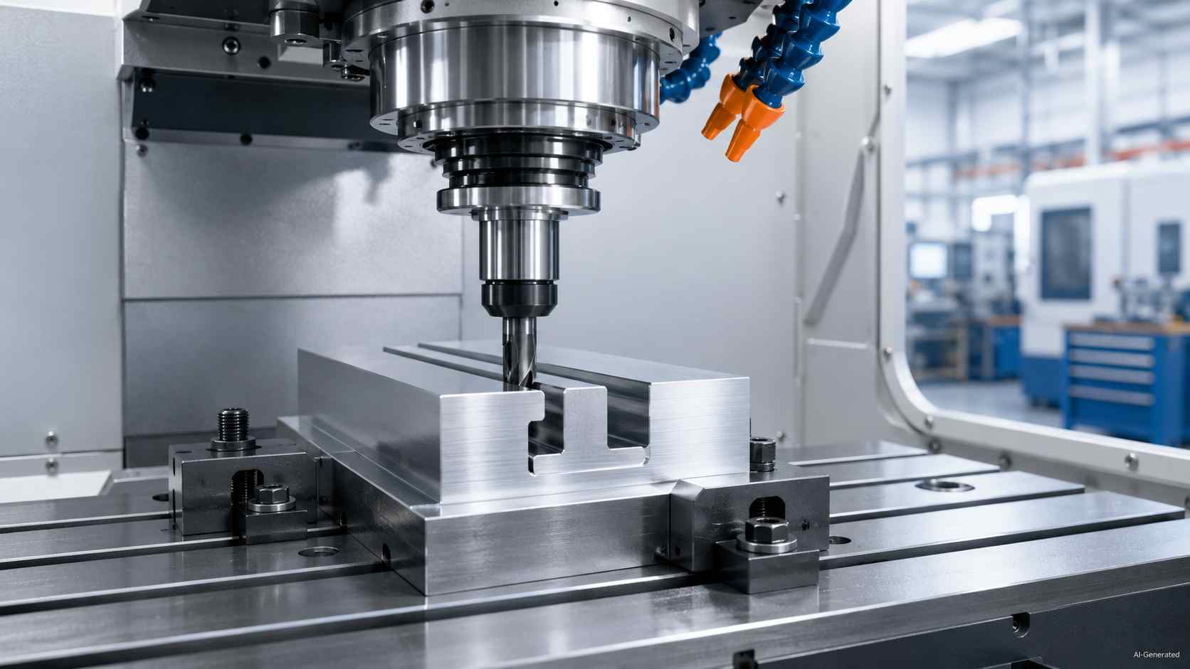
CNC T-slot milling cutter machining metal workpiece
What Is T-Slot Milling in CNC Machining
T-slot milling is a CNC operation that forms an undercut groove with a narrow upper passage and a wider lower pocket. It provides bolts or nuts with a guided path for clamping.
Geometry Compared with Straight Slots
Unlike an ordinary milled channel, a T-slot has hidden width below the surface, which allows hardware to slide along the length as well as remain retained under load.
Where These Features Are Used
In the context of T slot CNC work, you can commonly find this kind of shape on machine tables, fixture plates, modular frames, and assembly rails. That is where T-nuts, bolts, clamps, or brackets need adjustable holding points without additional drilled holes.
How the T-Slot Milling Process Works
Initial Slot Milling Before Undercutting
T-slot milling usually begins with a standard end mill that machines the initial slot opening. In many CNC workflows, this first stage follows the same basic principles used in conventional slot milling before the undercut profile is formed with a T-slot cutter. This is because the later tool needs room to pass through the upper layer before shaping the hidden lower area.
T Slot Cutter Machining and Undercut Formation
After that, the wider head of the cutter travels through that prepared passage and removes material underneath. It creates the T-slot profile without forcing the tool into solid stock.
Finishing, Deburring, and Inspection
After the cut, T slot machining moves into edge break, chip removal, and checking the inner shape. Remaining burrs or trapped debris can hinder the smooth movement of clamping hardware.
Why T-Slot Milling Is Difficult in CNC Machining
T-slot milling introduces machining conditions that are more restrictive than standard slot cutting. The cutter removes material beneath a narrow opening, which limits tool rigidity, chip evacuation, coolant access, and visibility during machining. As slot depth and length increase, small stability problems can quickly affect dimensional accuracy and surface condition.
Undercut Geometry Restricts Tool Access
Unlike a standard end mill operation, T-slot milling cuts material underneath the top surface. The cutter head must pass through a narrow opening while machining a wider internal cavity below it. This geometry increases tool overhang and reduces rigidity, especially in deep features or narrow slots.
Chip Evacuation Inside Deep Grooves
Chips are harder to remove once they collect inside the undercut section of the slot. In deeper grooves, trapped chips may recut against the tool edge, increasing heat, surface damage, and cutter wear. Air blast, coolant direction, and feed balance all become more important as slot depth increases.
Cutter Neck Deflection and Vibration
T-slot cutters typically use a thin neck between the shank and cutting head. Under cutting load, that section can flex more easily than a standard end mill. Long reach, interrupted engagement, or unstable workholding may amplify vibration and leave chatter marks inside the groove.
Coolant Access and Heat Build-Up
Coolant has limited access to the buried cutting zone during T-slot machining. Heat can build up around the cutter head, particularly in steel or stainless steel parts, where chip evacuation is slower. Insert wear and edge breakdown usually accelerate when coolant flow becomes inconsistent.
Burr Formation at Slot Exits
Burrs often appear where the cutter exits the workpiece or breaks through the slot edge. Thin unsupported material near the exit can bend instead of separating cleanly, especially in softer aluminum grades. Secondary deburring is commonly required when T-slots are used for sliding nuts, clamps, or precision fixture alignment.
T-Slot Cutters and Machining Stability
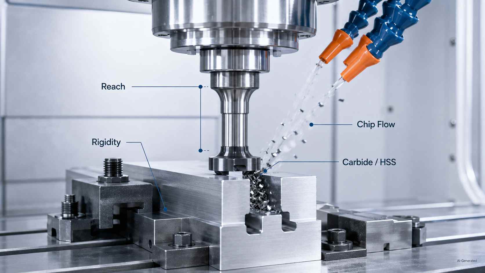
Alt Tag: T-slot cutter stability with chip flow and coolant
Cutter Geometry and Reach Limits
A T-slot cutter uses a wide cutting head with a narrow neck and shank, so tool selection usually begins with head width, neck relief, and usable reach before cutting parameters are finalized. Insert-style T-slot cutters typically have maximum cutting depths ranging from 8 to 15 mm, depending on the insert size.
Chatter Risk During T Slot Milling
The cutter head removes material under the top face while the neck passes through a narrow opening. Excessive overhang, insufficient holding force, or imbalanced feed can increase vibration.
Carbide and HSS Choices
For a T-slot, carbide suits CNC production where wear resistance and heat tolerance are important. HSS can work well for lower-speed jobs that need toughness and easier resharpening.
Dimensional Accuracy and Surface Finish in T-Slot Milling
Critical Dimensions in T-slot Features
Width, depth, shoulder height, and datum location determine whether the groove can accommodate mating hardware. Proper specification ensures steady movement and repeatable clamping accuracy. For reference, some DIN 650 T-slot configurations intended for M24 hardware use opening widths around 28 mm, with overall slot dimensions varying by table design and standard class. Undercut dimensions are often harder to inspect than open slots because the lower profile is partially hidden beneath the top surface.
Surface Finish Challenges Inside the Groove
The inner faces of a T-slot require controlled surface roughness, as sliding contact, friction, and wear depend on more than just dimensional accuracy.
Tolerance Stack-Up in Assembly Applications
Small variations across T-slot faces can accumulate during assembly. Specifying matched dimensions and inspection requirements on the drawing is necessary. In some thin-wall or deep-slot conditions, 6061-T6 aluminum can show dimensional movement on the order of 0.05-0.10 mm after machining due to residual stress release.
Material Considerations in T-Slot Milling
Aluminum vs Steel T-Slot Machining Behavior
Aluminum requires lower cutting pressure, but its tendency to smear can leave raised edges. Yet, steel resists the tool more as well as brings higher loads and greater heat into the job.
Material Effects on Surface Finish and Edge Integrity
Softer aluminum grades may smear along the slot edge, while harder steels tend to leave tearing marks if chip evacuation becomes unstable.
Tool Wear and Cutting Stability Across Materials
In T slot machining, material choice affects tool life from the first pass. A T-slot made in tougher stock needs more attention to heat, load, and wear than one made in easier-cutting aluminum.
Geometry Challenges in T-Slot Milling
Deep Slots and Cutter Reach Limitations
In T-slot milling, increased slot depth reduces tool access and increases overhang, making tool reach a critical design consideration before programming. A shorter projection gives the setup better control, but deep recesses may need staged material removal.
Thin Walls and Distortion Risks
When milling near thin walls, cutting forces can deform the part. Proper clamping and controlled tool engagement are essential to maintain geometry within tolerance.
Long Rails and Vibration Control
Long T-slotted rails can amplify vibration, resulting in wavy surfaces unless proper support, feed rates, and toolpath strategies are applied.
Design Considerations for T-Slot Features
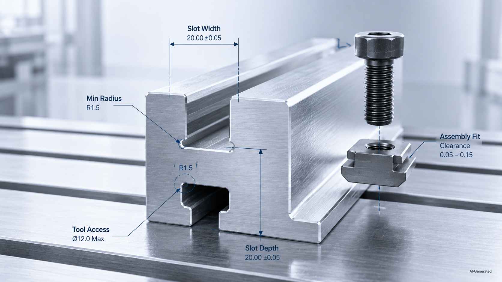
Alt Tag: T-slot design dimensions with bolt and T-nut alignment
Tool clearance rule
T-slot designs should always consider cutter head diameter and neck clearance. Undersized slots can prevent proper cutter entry and increase tool deflection risk.
Standard sizing rule
Most T-slot systems follow DIN 650 or similar standards, with common widths ranging from 10 mm to 20 mm depending on bolt size and application.
Depth ratio rule
Slot depth should not exceed the tool diameter ratio limits, or cutter deflection will significantly affect dimensional accuracy.
Assembly clearance rule
T-nuts and sliding hardware require controlled clearance; insufficient allowance leads to binding during assembly.
For production-ready t-slot parts, early manufacturability review is critical to avoid cutter access and tolerance issues.

Precision CNC Machining Service
Professional manufacturing, fast turnaround, and quality assurance.
Common Manufacturing Defects in T-Slot Milling
Burr Formation at Slot Exit
Burrs commonly form at slot exits due to unsupported material bending or fracturing instead of cleanly separating.
Cutter Deflection and Slot Width Error
T-slot cutters can deflect under cutting forces, potentially causing groove widening on one side or taper along its length.
Vibration Marks Inside the Undercut
Unstable tool motion can produce rhythmic marks inside the channel, creating a wavy surface indicative of chatter.
Poor Flatness in Long T-Slot Rails
A T slotted rail can lose flatness when clamping, heat, or uneven cutting load pulls the work away from its intended plane, which later affects alignment across the assembly.
T-Slot Milling vs Other Slot Machining Methods
T-Slot Milling vs Standard Slot Milling
Standard grooves are suitable for open channels, such as for keys, wires, or locating features. T-slot milling, by contrast, provides captured movement for clamps or nuts. This design offers greater assembly control but requires specialized tooling and careful planning.
T-Slot Milling vs Dovetail Machining
Dovetail cuts use angled faces for wedging and guided sliding. In contrast, T-slot frames require a broader underside for modular fastening. The choice between the two depends on whether adjustable clamping or angled mating contact is required.
Conclusion About T-Slot Milling
T-slot milling works best when cutter access, slot geometry, and dimensional control are planned together before machining begins. Because the undercut profile limits tool reach and inspection access, small setup changes can affect stability, surface finish, and final fit.
JLCCNC supports custom T-slot machining for fixture plates, rails, and other precision CNC components across aluminum, steel, stainless steel, and engineering plastics. CAD files can be uploaded for fast quoting, with pricing starting from $1 and lead times as short as 3 days, depending on part geometry and production requirements.
Precision CNC Machining Service
Professional manufacturing, fast turnaround, and quality assurance.
FAQ About T-Slot Milling
Q: What tools are used in T-slot milling?
T-slot milling typically uses two tools: an end mill to cut the initial straight slot, followed by a T-slot cutter to machine the undercut section. Carbide cutters are commonly used for better rigidity, wear resistance, and dimensional stability.
Q: What materials are best for T-slot machining?
Aluminum is easier to machine and evacuates chips efficiently, making it common for fixture plates and lightweight components. Carbon steel is widely used for structural applications, while stainless steel is more challenging due to higher cutting forces, heat buildup, and burr formation.
Q: What is a T-slot in CNC machining?
It is a machined groove that is shaped like a letter T and gives a narrow upper passage with a wider undercut below for the purpose of guided clamping hardware.
Q: Why does T-slot milling require special cutters?
Ordinary end mills are not able to create the concealed underside on their own, and this is the reason why shops utilize a formed cutter after opening an entry groove.
Q: What causes chatter during T-slot milling?
Chatter usually appears when the cutter overhang becomes excessive or when chips remain trapped inside the undercut area. Deep slots and narrow neck cutters are especially sensitive to vibration.
Q: How accurate can CNC T-slot milling be?
Accuracy depends on machine condition, cutter runout, workholding, thermal growth, material behavior, and inspection method. Tighter work needs more process control.
Q: How do manufacturers reduce burrs in T-slot machining?
Manufacturers are able to reduce burrs through the use of sharp tooling, appropriate feeds, exit support, coolant, air blast, and secondary edge-breaking after machining.
Popular Articles
• Cutting with Precision: A Comprehensive Guide to CNC Water Jet Technology
• CNC Coolant Explained: Types, Maintenance & Safety
• Rake Angle in Machining: Machinists’ Guide to Perfect Cuts
• What Steps Are Taken To Minimize Waste In CNC Machining Processes?
• How EDM Wire Cutting Works: Complete Guide to Precision CNC Wire Cutting
Keep Learning
Chatter in Machining: Causes, Effects, and How to Reduce It
CNC milling operation producing visible chatter marks on an aluminum workpiece Quick Chatter Diagnosis Checklist Symptom Most Likely Cause First Action High-pitched squeal Regenerative chatter Change spindle speed ±15% Chatter only in deep pockets Excessive tool overhang Shorten tool Chatter on thin walls Low workpiece rigidity Improve fixturing Chatter after tool replacement Runout / holder issue Check tool holder Chatter only during finishing DOC too small / rubbing Increase feed or adjust speed It ......
What Is Tool Offset in CNC? Types, Setup & Best Practices
CNC tool offset setup with measurement overlay Key Takeaways CNC offsets connect programmed intent with actual cutter position. Length data guides Z-axis depth control. Radius data protects part size during contour milling. Geometry values define the cutter's measured baseline. Wear values support fine correction during production. Verified data lowers scrap risk before full machining. Good offset habits protect tools, fixtures, and parts. In the context of CNC machining , tool offset is the quiet set......
Trochoidal Milling: Complete Guide to High-Efficiency CNC Machining
Key Takeaways Trochoidal milling combines circular cutter motion with continuous forward feed. The cutter normally engages 5 to 20% of its diameter instead of making a full-width cut. A smaller engagement angle limits force changes during slotting and pocket roughing. Low radial engagement often allows greater axial depths of cut than conventional slot milling. CAM software calculates the circular path automatically from the selected machining parameters. This strategy is widely applied to titanium, s......
What Is Die Casting? Process, Materials, and Applications
Key Takeaways Die casting is a metal casting process that forces molten metal into a reusable steel mold under high pressure, producing parts with tight tolerances and good surface finish at high volume. Aluminum die casting is the most common form by far, thanks to its combination of light weight, decent strength, and good corrosion resistance. The die casting process runs through mold preparation, injection, cooling, and ejection in a cycle that can repeat every few seconds to minutes depending on p......
First Angle vs Third Angle: Understanding Orthographic Projection Methods
Key Takeaways Orthographic projection is the system that lets a 3D part be represented through multiple 2D views, front, top, side, and so on. First angle projection and third angle projection are the two standard methods for arranging those views, and they place views in opposite positions relative to the object. First angle projection is the ISO standard used across most of Europe, India, China, Russia, and many other countries following ISO standards Third angle projection is the standard in the Un......
Micro EDM Machining: Capabilities, Materials, and Applications for Precision Components
Key Takeaways About Micro EDM Machining Only electrically conductive materials can be machined. Hole diameters can reach below 50 μm on specialized equipment. The process produces almost no mechanical cutting force, making it suitable for thin or delicate features. Surface integrity still requires attention because recast layers and heat-affected zones may remain after machining. Micro EDM is often combined with CNC machining, with milling producing the main geometry before EDM finishes critical micro......