Angle Milling Process and CNC Angular Milling for Precision Parts
25 min
- What Is Angle Milling?
- Angle Geometry and Milling Orientation
- Angle Milling Process for CNC Machined Parts
- CNC Angle Milling Tools and Cutting Techniques
- Angular Milling for Complex CNC Components
- Materials Used in CNC Angle Milling
- Common Challenges in Angle Milling
- Advantages and Limitations of Angle Milling
- Angle Milling vs Other CNC Milling Operations
- How to Optimize CNC Angle Milling Performance
- FAQs About Angle Milling
Key Takeaways
- CNC angle milling covers everything like simple edge chamfers on a 3-axis machine to precision compound-angle surfaces on 5-axis equipment.
- Chamfer milling uses dedicated chamfer mills or countersink tools for edge preparation; bevel milling cuts larger angled faces for weld preparation and structural features.
- Angular accuracy in angle milling depends on tool geometry accuracy, workpiece setup, and, in tilted-axis operations, the calibration of the rotary axis.
- The angle milling process produces surfaces that are harder to inspect than flat faces, which is why inspection strategy is part of the process planning rather than an afterthought.
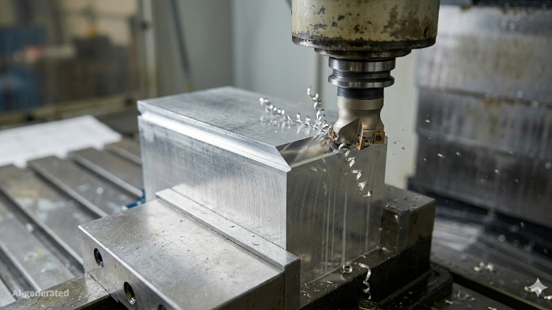
(AI generated) CNC chamfer milling on a machined edge
Flat surfaces are straightforward to machine. However, once a part requires an angled face, an assembly chamfer, a weld-prep bevel, or an angular pocket for a dovetail, the machining process becomes more complex.
Angle milling is the process used to machine these features accurately. Success depends on the relationship between tool geometry, workpiece orientation, and the functional requirement of the finished surface.
This process is not covered in much detail in most machining guides. Angle milling sits between the obvious operations, facing, slotting, profiling, and the specialized ones, and most shops develop their approach through trial and error rather than first principles. At JLCCNC, angle milling strategies are built around actual production constraints (tool reach, rigidity, setup count, cutter engagement, surface finish requirements) and not just CAM simulation screenshots.
That is the difference between merely cutting an angled feature and producing parts that assemble correctly without secondary fitting or rework.

Precision CNC Machining Service
Professional manufacturing, fast turnaround, and quality assurance.
What Is Angle Milling?
Definition of Angle Milling
Angle milling is a CNC machining operation used to produce surfaces, edges, or features at a defined angle to the primary machining plane. It can be performed with angular cutting tools, tilted workpiece setups, or coordinated multi-axis motion.
How Angle Milling Works
Three approaches to angle milling, each suited to different situations.
The first approach uses angular tooling in a standard machine setup. A chamfer mill, bevel cutter, or single-angle cutter is mounted in the spindle vertically, and the tool's own geometry generates the angle as it cuts. The machine moves in standard X, Y, Z, the angular surface comes from the tool shape, not axis tilting. This is the most common approach for chamfer milling and edge preparation because it's fast, accessible on any 3-axis machine, and needs no special setup.
The second approach uses a tilted workpiece setup. The part is set up on an angled fixture or sine plate, tilting it so the angled surface becomes horizontal relative to the spindle. A standard end mill then machines what is, from the tool's perspective, a flat face, but on the part, it's at the programmed compound angle. This works well for large angled faces where a purpose-made angular cutter would be expensive or unavailable.
The third approach uses simultaneous multi-axis cutting. On 4 or 5-axis machines, the spindle tilts relative to the workpiece, or the part rotates under the spindle, to generate angled surfaces through coordinated axis movement. This is how complex angular milling operations on aerospace and automotive parts are handled, producing compound angles, swept bevels, and angled pockets that neither angular tooling nor tilted setups can reach.
Why Angle Milling Is Used in CNC Machining
Weld joints need beveled edges so the filler material can penetrate and create a full-strength weld. Assembly features need chamfers so mating components guide into position rather than hanging up on sharp corners. Dovetail slots and T-slots need angular walls for the mechanical locking geometry that defines their function. Aerospace structural parts have angled faces dictated by aerodynamic and weight requirements. None of these features can be made without the CNC angle milling process.
The 45-degree chamfer on a drilled hole, the broken edge on a milled pocket wall, the lead-in on a threaded bore, all of these are angle milling operations, even if they're so routine they don't get called that.
Angle Geometry and Milling Orientation
Angular Surfaces, Chamfers, and Bevel Geometry
Angular surfaces in machined parts fall into a few categories, and understanding which category a feature belongs to determines the angle milling approach.
- Edge chamfers are the smallest category of angular feature. They are short angled transitions at part edges, typically 0.5–3 mm wide and cut at 30°–60°.
- They exist to remove sharp edges, guide assembly, and prevent stress concentration at corners. Chamfer milling for edge prep uses a chamfer mill or countersink tool in a brief operation that adds seconds to cycle time.
- Bevel faces are larger angled surfaces used for weld preparation, structural interfaces, or seating surfaces for conical components. Typical bevel angles are 30°–45° .
- Bevel milling produces these larger faces and requires more careful consideration of tool selection, workpiece support, and cutting parameters than edge chamfering.
- Angular pockets and slots have walls at compound angles, dovetail slots with 60-degree walls, T-slot undercuts, angular grooves for retaining rings and seals. These require either dedicated form tools (dovetail cutters, T-slot cutters) or multi-axis angular milling with standard tooling.
- Compound angles, faces that are angled in two planes simultaneously, are the most complex angle milling geometry. A surface that slopes 15 degrees in X and 8 degrees in Y simultaneously needs either a tilted workpiece with careful sine plate calculation or a 5-axis simultaneous cutting operation.
Cutting Angle vs Surface Angle
This distinction trips people up. The surface angle on the finished part is not the same as the cutting angle, the angle at which the tool approaches the surface.
A chamfer mill with the appropriate included angle can cut 45° chamfer when the tool axis is perpendicular to the reference surface and the programmed depth is correct.
That's straightforward. But when a standard end mill tilts on a 5-axis machine to cut an angled surface, the surface angle equals the tilt angle of the tool relative to the workpiece, and that relationship changes continuously if the tool moves across a curved surface.
For angular milling with dedicated angled tools, the surface angle is fixed by the tool geometry and the orientation is straightforward to set up.
For multi-axis angle milling with tilted standard tools, the relationship between commanded axis position and actual surface angle requires careful CAM programming to produce the correct geometry, particularly on surfaces where the angle changes along the length of the cut.
Tool Orientation and Workpiece Positioning
For any angle milling operation, two things need to be defined: where is the tool relative to the workpiece, and where is the workpiece relative to machine coordinates. Getting either wrong produces angular error in the finished surface.
In practice, angular accuracy depends on both workpiece positioning and tool orientation, especially on multi-axis machines where rotary-axis condition affects the final result.
Angle Milling Process for CNC Machined Parts
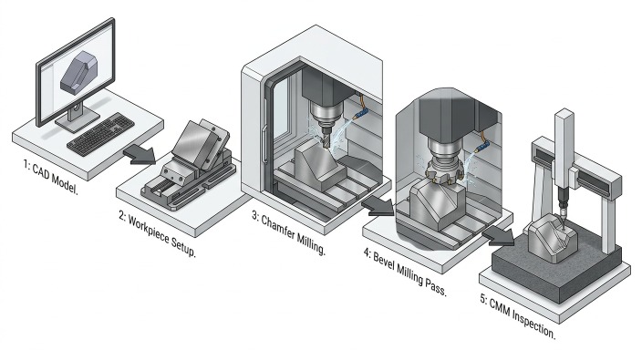
(AI generated) CNC angle milling process workflow diagram
Setup and Accuracy Control
Accurate angle milling starts with correct workpiece location and a clear relationship between the drawing datums, the fixture, and the machine coordinate system. If the angled feature is referenced to a primary face, that face must be seated against the fixture datum and verified before cutting begins. Even a small setup error can create measurable angular deviation across a long bevel or angled surface.
For standard 3-axis angle milling with chamfer mills, bevel cutters, or other angular tools, setup accuracy depends mainly on part location and datum alignment. Reference surfaces should be indicated when angular accuracy is important, rather than assumed to be correct based on visual positioning. When the feature angle itself is the controlling datum, an angled fixture, sine plate, or sine bar may be used to orient the workpiece more precisely.
On 4-axis and 5-axis machines, rotary-axis condition becomes part of the accuracy chain. Tool orientation depends not only on CAM output, but also on rotary-axis calibration, backlash, and machine thermal stability. As the distance from the center of rotation increases, even small angular errors can produce larger positional deviation at the cutting point.
For tighter-tolerance features, setup verification should be treated as part of the machining process rather than a separate check. Common controls include indicating datum faces before machining, confirming fixture alignment, verifying rotary-axis calibration on multi-axis equipment, and inspecting the first part before full production begins. Tool condition also matters: as a chamfer mill or bevel cutter wears, its effective cutting geometry changes slightly, which can affect chamfer width, angle consistency, and surface finish.
In precision work, thermal stability should also be considered. Heat buildup in the machine, fixture, or workpiece can slightly change orientation and position during long runs. For close-tolerance angle milling, allowing the setup to stabilize before first-part approval helps reduce variation that is caused by temperature rather than by the toolpath itself.
Toolpath and Angular Cutting Operations
For chamfer milling with a dedicated chamfer tool, the toolpath is simple: position the tool at the edge, set the depth that produces the required chamfer width, and feed along the edge. The chamfer width is a function of the tool angle and the depth of cut, a 45-degree chamfer mill cutting 0.5mm deep produces a 0.5mm x 0.5mm chamfer on a 90-degree edge.
For bevel milling of larger angled faces with angular tooling, the toolpath needs to account for the full face width. Multiple passes may be needed to cover the full bevel if it's wider than the tool can reach in one pass. The stepover between passes determines the scallop height and surface finish on the bevel face.
For multi-axis angle milling, the CAM system generates the tool orientation and position simultaneously. The programmer sets the surface normal angle, the tool vector, and the contact point, and the CAM calculates the simultaneous axis movements required to maintain those relationships as the tool moves along the surface. The operator must verify the setup before the program runs. A toolpath that looks correct in simulation can still produce errors if the part is not located exactly where the program expects it to be.
Inspection of Angled Features
Angled features are usually harder to inspect than flat surfaces because the acceptance criteria often include both angle and location. The inspection method should therefore be defined together with the tolerance requirement. If the drawing specifies a tight angular tolerance but does not define how the feature will be measured, the result can be disagreement between machining and quality teams even when the part appears acceptable.
For general chamfer milling, inspection may be relatively simple. Non-critical chamfers are often checked visually or with a chamfer gauge to confirm width and consistency. Hole-entry chamfers and countersinks may also be checked with dedicated gauges when the feature is tied to assembly or fastener seating.
For bevel milling and other functional angled surfaces, angle gauges, profile templates, and optical comparators may be used to verify bevel angle, land width, and overall profile. These methods are practical for weld preparation features, lead-in surfaces, and other geometries where the angle must match a process or assembly requirement.
For precision angular faces, compound angles, or tightly toleranced multi-axis features, CMM inspection is usually the most reliable approach. A proper CMM probing strategy can evaluate both surface location and surface normal direction, allowing the measured angle to be compared directly with the nominal geometry. This is especially important when the feature must be controlled relative to part datums rather than measured as an isolated surface.
Inspection planning should also account for process drift. First-part approval, in-process checks, and tool-change intervals help catch variation caused by tool wear, setup movement, or thermal change before an entire batch is affected. In other words, angle milling accuracy is controlled not only by machining strategy, but also by a measurement strategy that matches the function of the feature.
Surface finish in angle milling typically ranges from Ra 0.8 to 3.2 µm for general chamfers and bevels. Precision angular faces with finish passes may achieve Ra 0.4 to 1.6 µm, depending on tool condition, stepover, and material.
CNC Angle Milling Tools and Cutting Techniques
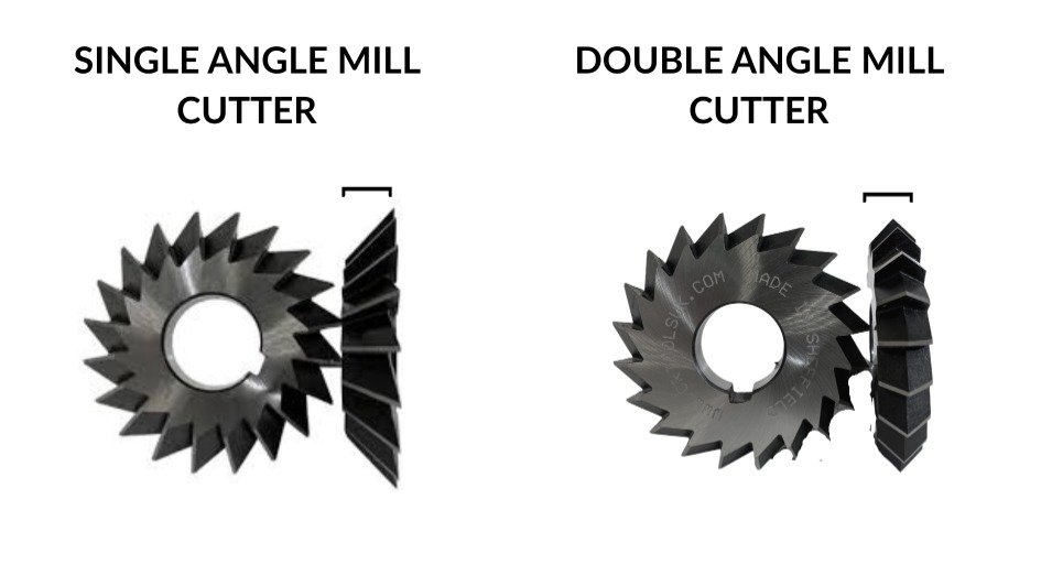
Single-angle vs double-angle milling cutters
End Mills and Tilting Toolpaths
Standard end mills can produce angular surfaces on multi-axis machines by tilting the tool vector relative to the workpiece. The end mill's peripheral cutting edges generate the angled surface as the tilted tool moves across the part. This approach is useful for angled surfaces that are too large for dedicated angular tooling or where the angle varies continuously along the surface.
The limitation of using standard end mills for angle milling is efficiency. A tilted end mill making a peripheral cut leaves a scalloped surface from the stepover between passes, finer stepovers improve finish but increase cycle time. Dedicated angular cutters that span the full surface width in one pass are more efficient for fixed-angle bevel milling operations at production volume.
Chamfer Mills and Bevel Cutters
Chamfer mills are the workhorses of edge angle milling. Standard included angles are 60°, 90°, and 120°, these cover the most common chamfer requirements across all industries. A 90° chamfer mill (45° half-angle each side) is the standard for general edge preparation. 60° chamfer mills produce steeper chamfers for weld preparation. 120° chamfer mills produce shallow, wide chamfers for seating and assembly features.
Bevel cutters for larger angular faces are essentially large-diameter chamfer mills with extended cutting length. They're used for CNC angle milling of full faces rather than just edges, a weld preparation bevel on a 50mm thick plate needs a tool that can span the full bevel depth in one or two passes rather than the multiple passes a standard chamfer mill would require.
Speed, Feed, and Cutting Angle Considerations
Cutting speed for angle milling follows the same material-dependent rules as any milling operation, surface speed in m/min based on the material and the tool material and coating. The complication for angle milling is that the effective cutting diameter changes with depth on chamfer mills and angled cutters, the effective cutting diameter near the tip is very small, and it increases toward the shank. Running a chamfer mill at spindle speed calculated for the maximum diameter runs too fast at the smaller effective diameters near the tip, which generates excess heat and accelerates wear at the tip.
Feed rate in chamfer milling is typically lower than equivalent flat milling operations for two reasons. First, the chip geometry on angled cutting edges is less predictable than on straight peripheral edges, the chip has to travel at an angle relative to the cutting direction, which can cause chip packing and edge loading. Second, precision chamfer milling where the chamfer width needs to be held to a tolerance requires controlled depth of cut, and lower feed rates give more consistent depth positioning on the entry pass.
Chamfer Milling and Bevel Milling Applications
| Application | Operation | Tool Used | Angular Requirement | Key Consideration |
|---|---|---|---|---|
| Edge deburring on machined parts | Chamfer milling | 90° chamfer mill | 45° typical, ±2° acceptable | Speed, minimal stock removal |
| Drilled hole entry chamfer | Chamfer milling | 90° countersink or chamfer mill | 45-90° | Depth control for consistent width |
| Weld preparation V-groove | Bevel milling | 60° bevel cutter or chamfer mill | 30° each side, ±0.5° | Land width and angle per weld procedure |
| Weld preparation J-groove | Bevel milling + radius | Chamfer mill + ball nose | Compound angle | Multi-pass, tight tolerance on angle |
| Dovetail slot | Angular milling | Dovetail cutter 45° or 60° | Fixed by cutter | Symmetry, width tolerance |
| T-slot undercut | Angular milling | T-slot cutter | Fixed by standard | Clearance for T-bolt head |
| Assembly lead-in chamfer | Chamfer milling | Chamfer mill | 15-45° | Consistent width across batch |
| Countersink for fastener | Chamfer milling | Countersink 82° or 90° | Fixed by fastener spec | Depth for flush seating |
| Aerospace structural bevel | Bevel milling | Custom bevel cutter | ±0.1° or tighter | CMM verification, full inspection |
| Automotive body panel edge | CNC angle milling | Chamfer mill or tilted end mill | 30-45° | Surface finish, cosmetic quality |
| Valve seat angle | Angular milling | Form tool or angle cutter | ±0.05° | Sealing performance depends on accuracy |
| Gear tooth chamfer | Chamfer milling | Small chamfer mill | 45°, tight width control | Deburring without tooth profile damage |
Angular Milling for Complex CNC Components
Multi-Axis CNC Milling Applications
5-axis CNC angle milling unlocks geometry that 3-axis machines with angled tooling simply can't produce. A surface that slopes in two directions simultaneously, common on aerospace structural components, turbine blade platforms, and complex die cavities, needs simultaneous tool axis control to machine correctly.
On a 5-axis machining center, the spindle tilts to maintain the correct cutting angle relative to the workpiece surface normal while the table or spindle moves through X, Y, Z. The angular milling operation is programmed in CAM as a surface normal direction rather than as specific axis angles, the CAM calculates the required A, B (or B, C) axis positions at each point along the toolpath to maintain the programmed surface contact angle.
For precision components, well-maintained 5-axis equipment can achieve very tight positional and angular tolerances, but the actual result depends on machine calibration, fixturing, part geometry, and inspection method. The angular accuracy is limited more by rotary axis calibration and thermal stability than by the control system's commanded accuracy.
Materials Used in CNC Angle Milling
Aluminum and Lightweight Alloys
Aluminum is the most forgiving material for angle milling. It cuts cleanly at high speeds, produces minimal burring at chamfered edges, and tolerates the varied chip thickness that angled cutting geometries produce. 6061-T6 is a common material for structural angle milling. With sharp carbide tooling, typical cutting speeds may fall in the range of 300-500 m/min, depending on machine rigidity, tool diameter, and coolant strategy.
7075-T6 machines similarly but with slightly higher tool loads from the harder alloy. The chamfer quality on 7075 is comparable to 6061 with sharp tooling and correct parameters. Both alloys show minimal burr at angled edges when the cutting edge is sharp, dull tooling produces folded burrs at chamfered edges that require secondary deburring.
Stainless Steel and Hardened Metals
Stainless steel angle milling requires more attention than aluminum. Work hardening is the key issue, 304 and 316 stainless harden rapidly under the cutting zone, and the variable chip thickness inherent in chamfer milling creates zones where the tool is partially rubbing rather than cutting cleanly. Sharp tooling, aggressive feed rates to stay below the work-hardened layer, and consistent cutting speed are essential.
For chamfer milling on stainless steel, TiAlN-coated carbide at 80-120 m/min with flood coolant produces consistent results. Dwelling the tool at the entry point, letting it rub rather than cut before feeding, work hardens the entry and causes premature wear. A solid entry engagement with immediate feed prevents this.
Hardened steel and tool steel angle milling requires CBN or ceramic tooling for materials above 50 HRC, or carbide with extreme caution below that hardness. The angled cutting geometry on chamfer mills means the tip region, which cuts at the smallest effective diameter, generates the most heat per unit area. In hardened materials this region wears first, which is why chamfer mill life in hardened steel is notably shorter than in soft materials.
Engineering Plastics and Composite Materials
Plastics machine cleanly in angle milling operations but require attention to heat and burr formation. POM and nylon produce clean chamfers at low speeds with sharp tooling and no coolant. Acrylic chips cleanly on chamfered edges but cracks if the tool is dull or the feed is too slow, generating heat that melts rather than cuts the material.
Carbon fiber composite angle milling is a specialist operation. The abrasiveness of carbon fiber wears carbide tooling rapidly, diamond-coated tools or PCD tooling extends life significantly. Delamination at chamfered edges is a risk with standard chamfer mill geometry, compression-cutting tool geometries that push fibers inward rather than pulling them outward at the exit edge reduce delamination on angle milling operations in CFRP.
Common Challenges in Angle Milling
| Challenge | Cause | Effect on Part | Solution |
|---|---|---|---|
| Angular error | Setup misalignment, incorrect tool geometry, axis calibration error | Wrong angle, assembly fit problem | Verify setup with angle gauge, inspect first part before full run |
| Chamfer width variation | Inconsistent depth of cut, tool wear changing effective geometry | Visual inconsistency, assembly issues | In-process depth verification, replace tool at defined interval |
| Tool deflection on long bevel cutters | Long reach bevel tools under lateral cutting force | Angled surface bows or tapers along length | Reduce depth per pass, use stub-length tools where possible |
| Burr at chamfer exit | Dull tool, incorrect feed direction, wrong exit geometry | Requires secondary deburring, affects assembly | Use climb milling for exit, replace dull tools, optimize exit path |
| Chatter on angled faces | Long tool overhang, insufficient workholding, poor cutting parameters | Chatter marks on angled surface, poor finish | Reduce overhang, increase feed, adjust spindle speed |
| Poor surface finish on bevel faces | Too-high feed rate, wrong stepover for required finish | Visible scallops, rough texture | Reduce feed on finish pass, use wiper insert if available |
| Compound angle error | Incorrect CAM programming, rotary axis error on 5-axis machine | Both angle components wrong | Verify CAM output, check rotary axis calibration |
| Undersize chamfer | Tool worn, incorrect depth setting | Assembly doesn't engage lead-in geometry | Verify depth with first-part inspection, update tool offset |
| Oversize chamfer | Too deep, incorrect tool angle assumed | Part rejected, material removed from critical edge | Check tool geometry before programming, verify depth setting |
| Delamination at edges (composites) | Standard chamfer mill pulling fibers at exit | Frayed edge, structural risk | Compression-cut tooling, correct feed direction |
Advantages and Limitations of Angle Milling
Precision and Surface Finish Benefits
Dedicated angular tooling, chamfer mills, bevel cutters, single-angle cutters, produces angular surfaces in one or two passes with consistent geometry defined by the tool rather than by programmed axis movements. For standard angles and common chamfer sizes, this produces highly repeatable results across a production batch without requiring multi-axis equipment. A 45-degree chamfer produced by a 90-degree chamfer mill at consistent depth is the same on part one and part five hundred as long as the tool is sharp and the depth is consistent.
Surface finish on angle milling operations with sharp dedicated tooling is comparable to flat milling at similar parameters, Ra 0.8-1.6 µm on finish passes is standard. The angled geometry doesn't inherently produce worse surface finish than flat operations; the finish is determined by the same feed rate, cutting speed, and tool condition factors.
Efficient Machining of Angled Features
CNC angle milling with purpose-made tooling is fast. A 45-degree chamfer on a part edge takes seconds. A weld preparation bevel takes one or two passes with a bevel cutter. Compared to the alternative, multiple axis interpolations with a standard end mill to approximate an angled surface, dedicated angular tooling produces the feature faster and more accurately.
For production volumes where angle milling operations repeat on every part, this efficiency compounds. A chamfer operation that takes 8 seconds per edge adds 8 seconds to every cycle. At 1,000 parts per year, that's 2.2 hours of machining time. At 10,000 parts, it's 22 hours. Angular tooling that completes the same chamfer in 3 seconds rather than 8 seconds saves 19 hours of machine time at 10,000 parts, without changing any other aspect of the process.
Tool Wear and Setup Challenges
The tip region of chamfer mills and bevel cutters is the first area to wear because it cuts at the smallest effective diameter and therefore the lowest surface speed. As the tip wears, the effective cutting geometry changes subtly, the chamfer angle produced may deviate slightly from nominal, and the surface finish degrades. For production work where chamfer width is a dimensional requirement, tool wear management, changing tools at defined intervals rather than running to failure, maintains consistency.
Setup complexity increases with angular accuracy requirements. A chamfer for edge deburring needs no special setup verification, the visual result is acceptable across a wide tolerance. An angular surface held to ±0.05° needs setup verification, first-part inspection, and periodic re-verification during the run. That verification time is real overhead that increases cost for high-accuracy angle milling operations.
Angle Milling vs Other CNC Milling Operations
| Factor | Angle Milling | Face Milling | Profile Milling | Slot Milling |
|---|---|---|---|---|
| Surface produced | Angled face, chamfer, bevel | Flat horizontal face | Contoured edge or profile | Slot with parallel walls |
| Tool type | Chamfer mill, angle cutter, tilted end mill | Face mill, shell mill | End mill | End mill, slot drill |
| Axis movement | X/Y/Z with angular tool, or multi-axis | X/Y at fixed Z | X/Y contour path | Z plunge then X/Y |
| Angular geometry capability | Native to the operation | None without tilt | Limited, requires multi-axis | None |
| Surface finish achievable | Ra 0.4-1.6 µm | Ra 0.4-1.6 µm | Ra 0.4-3.2 µm | Ra 0.8-3.2 µm |
| Typical tolerance | ±0.1-0.5° angular, ±0.05mm positional | ±0.01-0.05mm flatness | ±0.05-0.1mm | ±0.025-0.1mm |
| Setup complexity | Low for standard angles, high for compound angles | Low | Moderate | Low |
| Inspection method | Angle gauge, CMM | Surface plate, CMM | CMM, optical | Caliper, plug gauge |
| Production speed | Fast for simple chamfers | Very fast | Moderate | Moderate |
| Multi-axis requirement | Optional for simple, required for compound angles | No | Often | No |
| Where it's dominant | Edge prep, weld prep, angled faces | Large flat surfaces | Part profiles, contours | Slots, keyways, pockets |
How to Optimize CNC Angle Milling Performance
Toolpath Optimization
For chamfer milling on production parts, the toolpath should complete all edges accessible from one tool position before changing tool position, minimizing the number of approach and retract moves, which are non-cutting time. On a part with twelve edges to be chamfered, a toolpath that approaches and retracts twelve times separately takes longer than one that links the chamfer passes with short feed moves between adjacent edges.
For bevel milling of larger faces, the toolpath direction relative to the bevel face affects surface finish. Cutting with the tool feeding into the ascending side of the bevel (climb milling) produces better surface finish and less burr at the exit than conventional milling on angled faces. For CNC angle milling programs on 5-axis machines, the tool axis vector should be programmed as constant relative to the machined surface normal rather than relative to machine coordinates, this keeps the cutting conditions consistent across surfaces that change orientation.
FAQs About Angle Milling
Q: What is angle milling in CNC machining?
Angle milling is a CNC milling operation that produces angled surfaces, chamfers, and bevels using angular cutting tools, tilted workpiece setups, or coordinated multi-axis movement, generating geometry at a defined angle to the primary machining plane.
Q: What is the difference between chamfer milling and bevel milling?
While both generate angled profiles, they serve distinct structural roles. Chamfer milling typically removes a sharp corner to create a small, localized edge break (usually 0.5–3 mm at 45°) to aid assembly and eliminate burrs without extending through the full face. Bevel milling cuts a larger, sloping edge that often spans the entire thickness of the material face or section, primarily serving as a V-, U-, or J-groove configuration for weld preparation.
Q: What tools are used for angle milling?
Chamfer mills (60°, 90°, 120° included angle) for edge chamfering. Single-angle and double-angle cutters for angular slots and grooves. Bevel cutters for large angled faces. Standard end mills tilted on multi-axis machines for compound angular surfaces and large bevel milling operations where dedicated tooling is unavailable.
Q: Can CNC machines perform precision angular milling?
Yes. 3-axis CNC machines with angular tooling can achieve good angular accuracy on standard features, but the actual tolerance depends on fixture quality, tool condition, and how the feature is measured. 5-axis machining centers with calibrated rotary axes achieve ±0.05° or better on precision angular milling operations. The limiting factors are axis calibration, thermal stability, and inspection methodology rather than the control system's commanded accuracy.
Q: What is the difference between angle milling and angular milling?
They describe the same operation. Angle milling and angular milling are interchangeable terms for CNC milling operations that produce angled surfaces and features. Some sources use "angle milling" specifically for operations using dedicated angular cutters and "angular milling" for multi-axis operations with standard tools, but this distinction isn't universally observed in industry.
Keep Learning
Laser Engraving Aluminum: Marking Methods & Surface Effects
Key Takeaways Laser engraving usually removes base material to create a recess. Laser marking is a broader term that can describe a surface-color change or material removal, so the process name alone does not define the final result. On aluminum, alloy and surface finish affect marking contrast. A light mark on dark anodized aluminum is a common design target, but the actual appearance depends on the finish and laser process. JLCCNC laser marking produces a recessed area 0.03–0.1 mm deep. The result i......
CNC Cutting Fluid: Types, Functions, Applications, and Selection Guide
Key Takeaways Cutting fluid in machining performs four functions simultaneously: cooling the tool and workpiece, lubricating the tool-chip interface to reduce friction, carrying chips away from the cut zone, and protecting machined surfaces from corrosion between operations. Different machining operations need different fluid priorities: high-speed aluminum milling may need adhesion control and chip evacuation, threading and tapping need strong lubrication, and grinding requires both cooling and fine ......
Blind Hole Machining Guide: What Is a Blind Hole, Types of Holes, and Tapping Tips
What Is a Blind Hole? Types of Holes and CNC Hole Machining Explained In CNC machining, few operations challenge process control and tool stability as much as blind hole machining. A blind hole is a hole that terminates at a defined internal depth rather than breaking through the opposite surface. Because the cavity is enclosed at the bottom, chip evacuation, thermal behavior, tool wear, and dimensional accuracy become far more difficult to manage compared to through-hole machining. These constraints ......
Rake Angle in Machining: Machinists’ Guide to Perfect Cuts
What is Rake Angle? (minaprem) If you've ever stood in front of a CNC machine or a manual lathe, you know that the cutting tool's geometry isn't just some arbitrary design. Every angle, edge, and surface has a job to do, and one of the most important of those is the rake angle. We've been running machines long enough to know that rake angle can make or break your surface finish, tool life, and machining efficiency. In this guide, we're going to walk you through what rake angle is, how it works, and ho......
Sheet Metal vs CNC Machining: A Guide to Choosing the Right Method for Your Metal Parts
Quick Answer: Choose sheet metal for uniform-thickness enclosures, panels, and formed brackets when bends and production volume support lower unit cost. Choose CNC machining for variable wall thickness, precision bores, tight feature relationships, and complex 3D geometry. Use a hybrid design when a formed structure needs precision-machined interfaces. A quote comes back for a bracket, and it's priced as a CNC part — machined from solid aluminum, a few hours of spindle time, a per-part cost that makes......
What Steps Are Taken To Minimize Waste In CNC Machining Processes?
How to Reduce Waste in CNC Machining: 5 Practical Strategies Quick Answer: CNC machining waste is reduced mainly through DFM, near-net stock, efficient toolpaths, preventive tool maintenance, and alloy-segregated recycling. The biggest gains usually come before cutting: reduce unnecessary material removal and prevent scrap or rework. Every CNC-machined part starts as more material than it ends up being. A pocket gets milled out, a profile gets cut away, a boss gets faced down to size — and all of that......