Beveled Edge in CNC Machining: Definition, Types, and How to Specify
15 min
- What Is a Beveled Edge in CNC Machining?
- Types of Bevels Used in CNC Machining
- CNC Bevel Cutting Methods and Capabilities
- Materials Commonly Used for CNC Bevel Cutting
- Bevel vs Chamfer vs Fillet: Key Differences You Should Know
- Functional Reasons for Beveled Edges
- Design Considerations Before Adding a Bevel Cut
- CNC Beveled Edge Machining at JLCCNC
- FAQ
Designing the perfect edge isn’t always as simple as it seems during CNC machining. On a CAD model, a sharp corner might look fine. In reality, it can chip, cause fitment issues, and even pose safety risks during handling. We’ve seen plenty of projects where a minor oversight on edge design led to costly rework later.
At JLCCNC, we deal with bevels with meticulous care. Our team chooses the right tool, optimizes the cutting strategy, and selects the appropriate angle for each material. Therefore, we consistently produce clean, precise edges that don’t compromise your design or slow down production.
In this article, we’ll walk you through what beveled edges are in CNC machining. You’ll get a practical understanding of the different bevel types, how they’re cut, the common challenges, and tips for specifying them correctly.

What Is a Beveled Edge in CNC Machining?
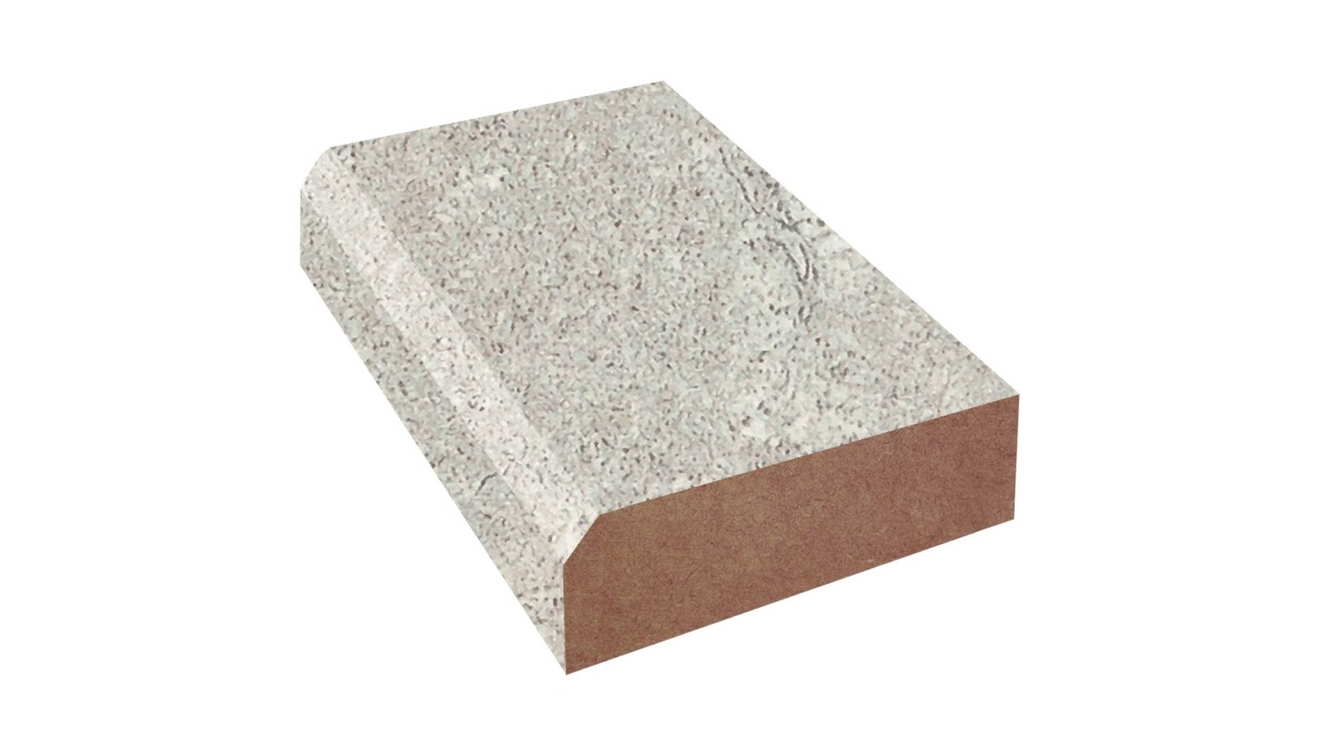
A close-up view of a beveled edge. [Source: cabinetmakerwarehouse.com]
A beveled edge in CNC machining is an angled cut applied to the edge of a machined part, replacing a sharp 90-degree corner. The bevel angle varies based on part design, material, and functional requirements, and is commonly used on metal brackets, plastic enclosures, and custom panels.
Beveled edges serve multiple critical purposes in CNC-manufactured parts:
● Improved Assembly: Bevels help guide parts during mating, reducing friction, alignment issues, and the risk of damage in tight-tolerance assemblies.
● Stress Distribution: By eliminating sharp corners, bevels reduce stress concentrations that can lead to cracking, fatigue, or premature failure under load.
● Operator Safety: Angled edges minimize sharp corners, lowering the risk of cuts, snagging, or damage during handling and installation.
● Aesthetic and Functional Finish: Beveled edges create a clean, professional appearance while preparing edges for fasteners, surface treatments, or further assembly steps.
At JLCCNC, each beveled edge is engineered according to the part’s material and application. We carefully select cutting tools, bevel angles, and feed rates to achieve consistent, burr-free edges without chipping or surface defects.
Types of Bevels Used in CNC Machining
In CNC machining, there are several common types of bevel used for functional and assembly purposes. Adequate beveling results in smooth assembly, reduces stress, and eliminates sharp edges that can cause safety hazards during handling.
Common Bevel Angles for CNC Parts
● Angle (15 to 30 Degrees): Shallow bevels. They are used for parts that require sliding and fitting together. These angles remove less material while still guiding parts together.
● Angle (30 to 45 Degrees): Steeper bevels. They disperse stress along the edge. Use this angle for custom brackets, supports, or parts that experience loading.
● Custom Angle: Some parts call for custom bevels to accommodate the part shape and specific types of fasteners. Our team programs the CNC machine to produce bevels with any required angle.
Single Bevel, Double Bevel, and Compound Bevel
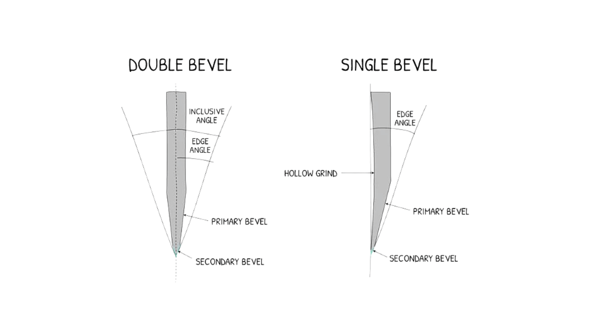
Diagram of single and double bevels, highlighting the primary and secondary bevel angles. [Source: dreamofjapan.com]
● Single Bevel: In single beveling, only one side of the edge is beveled. They are easiest to produce and the right fit for guiding parts together or to remove sharp corners. They are typically used on brackets, panels, and parts with minimal complexity.
● Double Bevel: In double beveling, both sides of the edge are beveled. They are suitable for symmetric parts and distribute loads evenly.
● Compound Bevel: A combination of bevels along the same edge, possibly including a flat section. Compound bevels are designed for parts with complex interfaces or to control stresses in specific areas of the part. They are more challenging to plan and execute; however, compound bevels are frequently used in high-precision applications.
Comparison Table of Bevel Types
Table 1: Common Bevel Types
| Bevel Type | Used For | Complexity | Benefit |
| Single Bevel | Simple assembly, remove sharp edges | Low | Helps parts fit together, and it is safer to handle |
| Double Bevel | Symmetrical parts, even stress | Medium | Balances forces, looks neat |
| Compound Bevel | Complex fit or high-stress applications | High | Ensures alignment, spreads load precisely |
CNC Bevel Cutting Methods and Capabilities
Beveled edges do more than add beauty to a part. They directly affect the assembly, safety, and stress distribution of the part. The precision beveling via CNC machines is dependent upon careful planning, selection of the appropriate cutting tool, feed, and setup of the machine. Understanding how beveled edges are created allows designers and engineers to avoid common errors in bevel creation, including chipped edges, improper angles, and bad fits.
How CNC Machines Cut Beveled Edges
CNC machines employ several techniques to cut a beveled edge, depending on the bevel type, material, and part intricacy:
Chamfer Milling: Chamfer milling is when a CNC machine cuts the edge of a part using a chamfer mill, commonly with 45-degree tools, though other angles are also used depending on design requirements. The angle, depth, and feed rate of the chamfer milling operation are specified during the programming stage based on the material. Aluminum, for example, can be rapidly machined with high feed rates, whereas stainless steel requires lower feed rates to avoid excessive heat build-up and burring.
Multi-Axis Milling: When parts entail multiple faces with angled features, 4- or 5-axis CNC machines are the go-to option. This enables double or compound bevels to be produced in a single setup. Multi-axis milling is particularly beneficial for aerospace brackets and precision housings where multiple edges come together at intricate angles.
Tilted Spindle End Milling: If the machine does not possess full multi-axis capabilities, the spindle can tilt to approximate the bevel angle. Tilted spindle end milling is applicable for simple single bevels. However, it is challenging for very steep or compound angles. Correct tool positioning relative to the part and adequate clamping are critical in this case; any misalignment can negatively affect the edge quality of the part.
Surface Finish Control: Bevels are defined by both geometry and surface finish. While creating bevels on flat surfaces is relatively easy and can be achieved with standard angled cutting tools, creating fillets with a radius tool or multi-axis milling requires additional effort to create a smooth curved edge.
Materials Commonly Used for CNC Bevel Cutting
Different materials behave differently when being beveled. Here are the common materials used for beveling.
Aluminum (6061, 7075): Aluminum is a lightweight and easy-to-machine material. It produces precise and smooth bevels when the feed is optimized correctly. However, if the feed is too rapid, the aluminum part will chatter. Similarly, if the feed is too low, it will produce marks on the part surface.
Stainless Steel (304, 316): Stainless steel is challenging to machine. It generates excessive heat during cutting operations. So, part edges can warp and cause work hardening. It is recommended to use slower feeds, sharp cutting tools, and rigid clamping systems.
Brass and Copper: Brass and copper are relatively soft and sticky. Thus, sharp cutting tools must be employed, and lubricants should be used to prevent smearing.
Plastics (ABS, Nylon, PMMA): Plastics are usually prone to melting when subjected to high spindle speeds. Properly managed feeds and sharp cutting tools are required to maintain a clean edge on plastics.
Steel Alloys: When machining steel alloys, it’s important to control the material removal, cutting angle, and feed rate. This helps you avoid burrs or uneven edges, especially on load-bearing parts.
Bevel vs Chamfer vs Fillet: Key Differences You Should Know
As discussed earlier, edge treatments on CNC parts are not merely aesthetic considerations because they directly affect the part assembly, strength, its safety, and ultimately its cost. The choice of an inappropriate edge treatment can result in parts that do not fit, wear out prematurely, and/or are more expensive to manufacture. Therefore, it’s imperative to understand the differences between bevels, chamfers, and fillets to allow you to design functional parts efficiently and cost-effectively.
Bevel vs Chamfer in CNC Machining
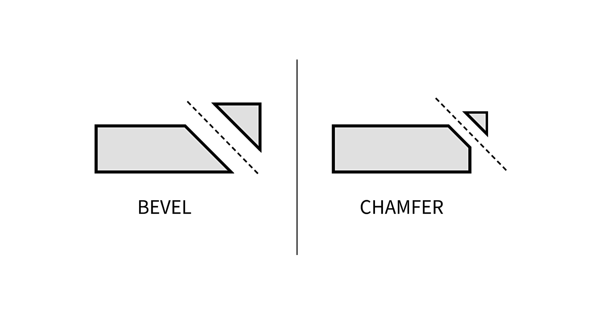
Illustration showing the difference between a bevel and a chamfer on a workpiece, highlighting their angles and edge styles. [Source: unionfab.com]
A beveled edge (angled edge) extends the entire length of a corner or edge. Bevels are commonly used to assist parts in mated assembly, to reduce the stress concentration in corners, or to remove sharp edges that could potentially harm machinists during handling.
A chamfer, on the other hand, is a straight, flat cut. It eliminates the sharp corner and is generally smaller and more discreet. It is frequently used for alignment during assembly and to minimize edge damage to the part during handling.
Ultimately, the main distinction lies in the intended purpose and angle of the bevel. Bevels can be shallow or steep. They are often used to meet functional requirements of the design related to the distribution of loads. Conversely, chamfers are generally shallow (typically 45°) and are almost exclusively used for fit and ease of handling.
Bevel vs Fillet in CNC Machining
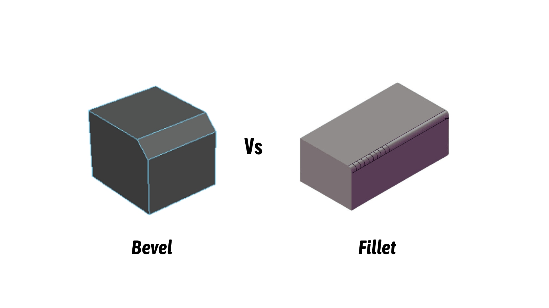
3D illustration comparing bevel and fillet edges on a component.
A fillet is a curved edge that rounds the sharp corner of a part. Unlike bevels, which create a sloped transition, fillets distribute the stress of the part throughout a larger area. Therefore, it reduces the likelihood of cracking or fatigue in highly stressed parts.
Bevels are relatively easy to produce on flat surfaces. They can be accomplished with a standard angled cutting tool. Fillets require radius cutting tools or multi-axis machining to create a smooth curved edge.
So, on a lighter note, use a bevel when you need angular edges for assembly and aesthetics. Employ fillet when you desire structural strength and stress relief.
When Should You Choose a Beveled Edge
Beveled edges play an important role in how CNC parts function, are assembled, and resist stress. The choice of proper bevel is dependent on understanding the part's intended function, material characteristics, and the interaction of the part with other components.
Chamfer vs Fillet vs Bevel: Quick Comparison Table
Table 2: Comparative Analysis (Chamfer Vs Fillet Vs Bevel)
| Factors | Bevel | Chamfer | Fillet |
| Edge Shape | Angled edge | Straight cut corner | Rounded corner |
| Typical Use | Assembly fit, load transfer, aesthetics | Ease of assembly, edge protection | Stress relief, fatigue reduction |
| Machining Method | Chamfer mill, multi-axis, tilting head | Chamfer mill, angled cut | Radius cutter, ball end mill |
| Complexity in Machining | Medium | Low | High |
| Material Suitability | Metals, plastics | Metals, plastics | Metals, plastics |
| Visual Appearance | Sleek, engineered look | Subtle, functional | Smooth, polished |
Functional Reasons for Beveled Edges
Assembly Alignment and Fit
Parts with beveled edges will fit into one another far more readily than without beveled edges. In assemblies with extremely close tolerances, a slight bevel prevents galling and misalignment, thus reducing the time spent during production.
For example, metal brackets that are required to fit into a frame will benefit from a 45-degree bevel along the contacting edges, thereby facilitating the bracket insertion into the frame without forcing or damaging it.
Stress Distribution
Concentrated stress tends to cause a sharp corner(weak points) that is susceptible to cracking or fatigue. A well-planned bevel distributes the load throughout a larger area, thus increasing durability. Components that repeatedly undergo loading conditions, such as automotive mounts or industrial brackets, will perform better and last longer when edges are beveled to manage stress.
Surface Contact and Mating
A bevel cut helps ensure that two parts seat properly at the point where they come into contact through fastening, welding, or sliding. It also provides a flat area for a screw to engage, which will allow it to sit flush against the surrounding material. When a bevel is applied, it gives a consistent performance characteristic from the mechanical standpoint and reduces the potential for wear over time.
Safety and Handling
Machined parts usually have sharp edges. These can harm operators and nearby equipment. The application of a smooth bevel to a component will significantly reduce such hazards while maintaining the operational integrity of the product. Bevels are particularly beneficial for products made from thin sheet metal or parts that are often assembled and disassembled.
Design Considerations Before Adding a Bevel Cut
Material and Machining Constraints
The material being machined determines how the bevel is cut. In general, hard materials like titanium or stainless steel require a slower feed rate and the appropriate tool geometry to avoid chipping of the workpiece material. While plastics and softer metals can be machined much quicker than hard metals, they still require close tolerance control.
Bevel Angle and Length
The bevel angle and length must be designed relative to the specific bevel function. If the bevel angle is too large, it may create difficulty during the assembly process. On the other hand, if the bevel angle is too slight, the stress concentrations within the part may not be sufficiently relieved. At JLCCNC, our engineers use both CAD (Computer Aided Design) modeling and simulation processes to determine the optimal bevel angles for each specific part to meet their design intent.
Multi-Axis Machining Requirements
Some bevels are constructed from compound angles and, therefore, may require 4- or 5-axis CNC machining processes to produce the desired geometric configuration. Tool paths are set based on part geometry and tolerance requirements to ensure high accuracy within ±0.05 mm.
Surface Finish Considerations
In addition to the geometric characteristics of the beveled edge, the surface finish quality can also impact the part's performance. For example, polished or anodized beveled edges can significantly reduce friction and corrosion and enhance the part's cosmetics. In the case of functional parts, our experts balance the required surface finish quality with machining efficiency to produce parts that are both strong and usable.
CNC Beveled Edge Machining at JLCCNC
At JLCCNC, we machine beveled edges with extra care to meet your functional and design requirements. Bevels improve part alignment, distribute stress, remove sharp corners, and ensure smooth assembly. Every edge is carefully controlled for accuracy, finish, and consistency.
Design Verification and Tool Path Planning
We review your CAD files to confirm bevel angles, lengths, and positions. Tool paths are simulated to prevent chatter, tool marks, or deviations. Multi-angle and compound bevels are executed using 4- and 5-axis CNC machines, meeting ISO 2768 quality standards.
Material-Specific Machining
Bevels are cut using optimized tooling and speeds based on material. Aluminum 6061, 7075, stainless steel 304, copper, brass, and engineering plastics like ABS, POM, and Nylon are handled with carbide or diamond-coated cutters. Feed rates are controlled to prevent chipping, deformation, or burrs.
Surface Finish and Accuracy
Edges are finished smooth and uniform, with options like bead blasting, anodizing, or conductive anodizing. We verify critical dimensions using CMM and precision measurement tools, achieving ±0.05 mm tolerances for metals and ±0.1 mm for plastics.
Our Benefits
● Transparent pricing with no hidden charges
● Burr-free surfaces for safety and functional performance
● Optimized bevel angles for stress distribution and mating surfaces
● ISO 9001:2015 certified quality and in-house inspection
● Rapid turnaround from prototypes to production
Contact us today to discuss your project and get an instant free online quote!
FAQ
Is a bevel the same as a chamfer in CNC machining?
No. A bevel is a larger angled edge that may serve structural or functional purposes, while a chamfer is usually a small 45° cut used to break sharp edges or aid assembly.
What is the standard bevel angle in CNC machining?
There is no single standard bevel angle. Common bevels range from 15° to 45°, depending on the part function, material, and assembly requirements.
What happens if I specify a bevel angle that’s hard to machine?
Steep or shallow angles are usually tricky, especially on hard metals like stainless steel. Non-standard angles often require special tools and multi-axis machining. Eventually, this adds cost and time. So, it’s better to check with your machinist before finalizing the design.
Should I model beveled edges in the CAD file or just note them?
If the bevel affects fit, assembly, or stress, it’s good to model it in CAD. For minor cosmetic edge breaks, a note like “break all sharp edges” is usually enough. CAD modeling generally avoids guesswork.
Can bevels weaken a part?
Yes, if a bevel removes material near a load-bearing area, it can make the part weaker. So, you must use fillets instead in high-stress zones to distribute forces.
Why do beveled edges sometimes come out wrong?
Incorrect angles usually come from tool setup, CAD/CAM direction, and choosing wrong feed speeds. Minor mistakes in setup can cause inconsistent bevels.
Can plastics like acrylic or ABS get clean bevels like metal?
Plastics can chip and melt if cut too fast or with the wrong tool. Using slower feeds, sharp tools, and sometimes light hand finishing usually gives clean edges.
Does a beveled edge make inspection more complicated?
Yes, a little bit. Bevels need their angle and width measured, often with a CMM or protractor. Adding precise tolerances on the drawing helps avoid errors.
Popular Articles
• Cutting with Precision: A Comprehensive Guide to CNC Water Jet Technology
• CNC Coolant Explained: Types, Maintenance & Safety
• Rake Angle in Machining: Machinists’ Guide to Perfect Cuts
• What Steps Are Taken To Minimize Waste In CNC Machining Processes?
• How EDM Wire Cutting Works: Complete Guide to Precision CNC Wire Cutting
Keep Learning
Chatter in Machining: Causes, Effects, and How to Reduce It
CNC milling operation producing visible chatter marks on an aluminum workpiece Quick Chatter Diagnosis Checklist Symptom Most Likely Cause First Action High-pitched squeal Regenerative chatter Change spindle speed ±15% Chatter only in deep pockets Excessive tool overhang Shorten tool Chatter on thin walls Low workpiece rigidity Improve fixturing Chatter after tool replacement Runout / holder issue Check tool holder Chatter only during finishing DOC too small / rubbing Increase feed or adjust speed It ......
What Is Tool Offset in CNC? Types, Setup & Best Practices
CNC tool offset setup with measurement overlay Key Takeaways CNC offsets connect programmed intent with actual cutter position. Length data guides Z-axis depth control. Radius data protects part size during contour milling. Geometry values define the cutter's measured baseline. Wear values support fine correction during production. Verified data lowers scrap risk before full machining. Good offset habits protect tools, fixtures, and parts. In the context of CNC machining, tool offset is the quiet setu......
Trochoidal Milling: Complete Guide to High-Efficiency CNC Machining
Key Takeaways Trochoidal milling combines circular cutter motion with continuous forward feed. The cutter normally engages 5 to 20% of its diameter instead of making a full-width cut. A smaller engagement angle limits force changes during slotting and pocket roughing. Low radial engagement often allows greater axial depths of cut than conventional slot milling. CAM software calculates the circular path automatically from the selected machining parameters. This strategy is widely applied to titanium, s......
What Is Die Casting? Process, Materials, and Applications
Key Takeaways Die casting is a metal casting process that forces molten metal into a reusable steel mold under high pressure, producing parts with tight tolerances and good surface finish at high volume. Aluminum die casting is the most common form by far, thanks to its combination of light weight, decent strength, and good corrosion resistance. The die casting process runs through mold preparation, injection, cooling, and ejection in a cycle that can repeat every few seconds to minutes depending on p......
First Angle vs Third Angle: Understanding Orthographic Projection Methods
Key Takeaways Orthographic projection is the system that lets a 3D part be represented through multiple 2D views, front, top, side, and so on. First angle projection and third angle projection are the two standard methods for arranging those views, and they place views in opposite positions relative to the object. First angle projection is the ISO standard used across most of Europe, India, China, Russia, and many other countries following ISO standards Third angle projection is the standard in the Un......
Micro EDM Machining: Capabilities, Materials, and Applications for Precision Components
Key Takeaways About Micro EDM Machining Only electrically conductive materials can be machined. Hole diameters can reach below 50 μm on specialized equipment. The process produces almost no mechanical cutting force, making it suitable for thin or delicate features. Surface integrity still requires attention because recast layers and heat-affected zones may remain after machining. Micro EDM is often combined with CNC machining, with milling producing the main geometry before EDM finishes critical micro......