Types of Rivets: Applications, Materials and Selection Guide
25 min
- What Is a Rivet?
- Types of Rivets
- Rivet Head Styles
- Comparing Different Rivet Types
- Rivet Materials
- Common Rivet Applications
- How to Choose the Right Rivet
- Design Guidelines for Riveted Parts
- Manufacturing Considerations for Riveted Parts
- How Rivets Are Installed
- Common Riveting Mistakes
- FAQs About Rivets
Key Takeaways
- The main types of rivets include solid, blind, semi-tubular, tubular, drive, and split rivets. Each type is selected according to installation access, material compatibility, and joint requirements.
- Rivet types and identification on drawings use standard callouts covering head style, material, diameter, and grip length.
- Different kinds of rivets require different installation methods. Some need access to both sides, others install from one side only.
- Rivet material must be compatible with the base material to avoid galvanic corrosion: aluminum rivets with aluminum sheet, stainless with stainless, and specific compatibility rules for mixed-material assemblies.
- Uses for rivets include applications where welding would distort the material, where vibration would loosen threaded fasteners, where both sides of the joint aren't accessible, and where rapid assembly of sheet metal components is required.
Rivets have been joining metal for over three thousand years. The Brooklyn Bridge uses them. Aircraft fuselages depend on them. Your laptop hinge probably has one. They're not glamorous, they don't adjust, and they're not going anywhere, which is exactly the point. A well-specified rivet creates a permanent joint that resists vibration, handles shear loads reliably, and doesn't loosen over time the way threaded fasteners can.
But there are many different types of rivets, each engineered for different materials, different installation conditions, and different structural requirements. Picking the wrong rivet type, or the right type in the wrong material, produces joints that fail in service or require destructive removal to fix. Understanding the different kinds of rivets, their uses, and how to select them correctly is the foundation of any riveted assembly that actually performs.
Choosing the correct rivet is only one part of building a reliable assembly. The hole quality, material thickness, and fabrication method all influence joint performance. Before riveting, the components must be manufactured with the required hole locations and fit conditions. CNC machining and sheet metal fabrication are commonly used to produce these parts, depending on the design requirements. Learn more about sheet metal fabrication processes to understand how riveted parts are manufactured before assembly.
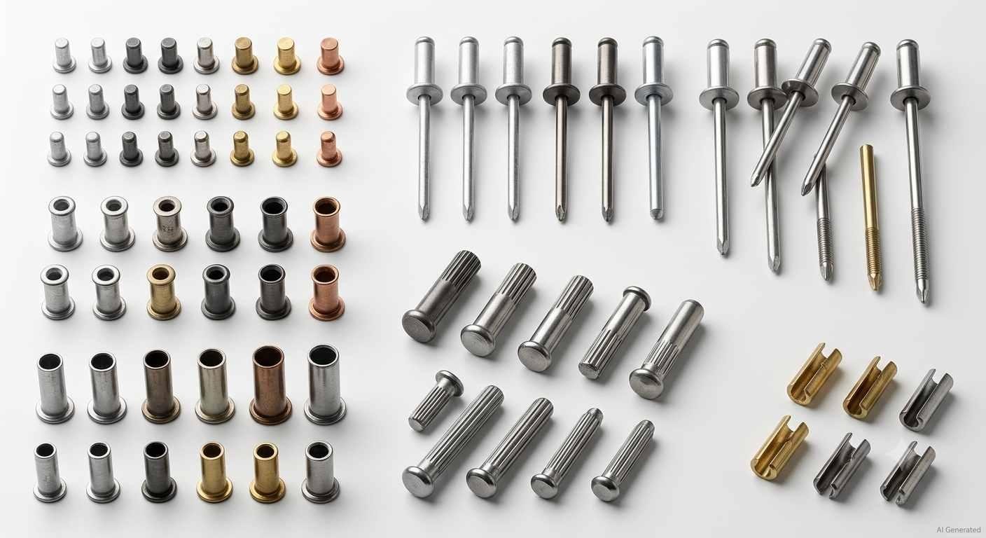
Various finished rivets
What Is a Rivet?
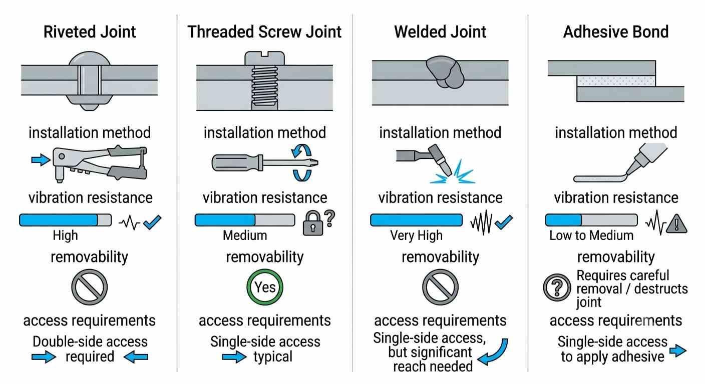
Comparing four common joining methods
A rivet is a permanent mechanical fastener consisting of a cylindrical shank with a preformed head on one end, installed through aligned holes in two or more workpieces and deformed on the opposite end to create a second head that clamps the joint together. Here's a detailed guide on what rivets are and how to remove them properly.
The deformation process, known as upsetting the rivet tail, is what makes a rivet permanent and what fundamentally distinguishes it from threaded fasteners. Once the tail is upset, the joint can only be disassembled by drilling out the rivet body. This permanence is the rivet's main characteristic, and it's simultaneously its primary advantage and its primary limitation.
Why Use Riveted Joints
Riveted joints outperform threaded fasteners in several specific conditions that define where uses for rivets make engineering sense.
Vibration resistance is the most common reason. Threaded fasteners can loosen under cyclic loading unless locked with adhesives, lock washers, or prevailing torque features. Riveted joints are resistant to rotational loosening because the deformed tail mechanically locks the fastener in place. Aircraft structural joints use rivets rather than bolts partly for this reason.
Thin sheet metal assembly is another primary use for rivets. Sheets too thin to carry threads efficiently join reliably with the different kinds of rivets designed for sheet metal, blind rivets and semi-tubular rivets in particular.
One-sided access justifies rivet selection over welding or through-bolting when one face of the joint is permanently enclosed. Blind rivets install entirely from one side, making them the only practical mechanical fastener for enclosed structures. See sheet metal fastening for more fasteners, methods and more.
Dissimilar material joining, connecting plastic to metal, or thin metal to composite, is another application where rivets suited to low-installation-force are preferred over welding (which requires compatible melting points) and over screws (which require adequate thread engagement depth).
Types of Rivets
1. Solid Rivets
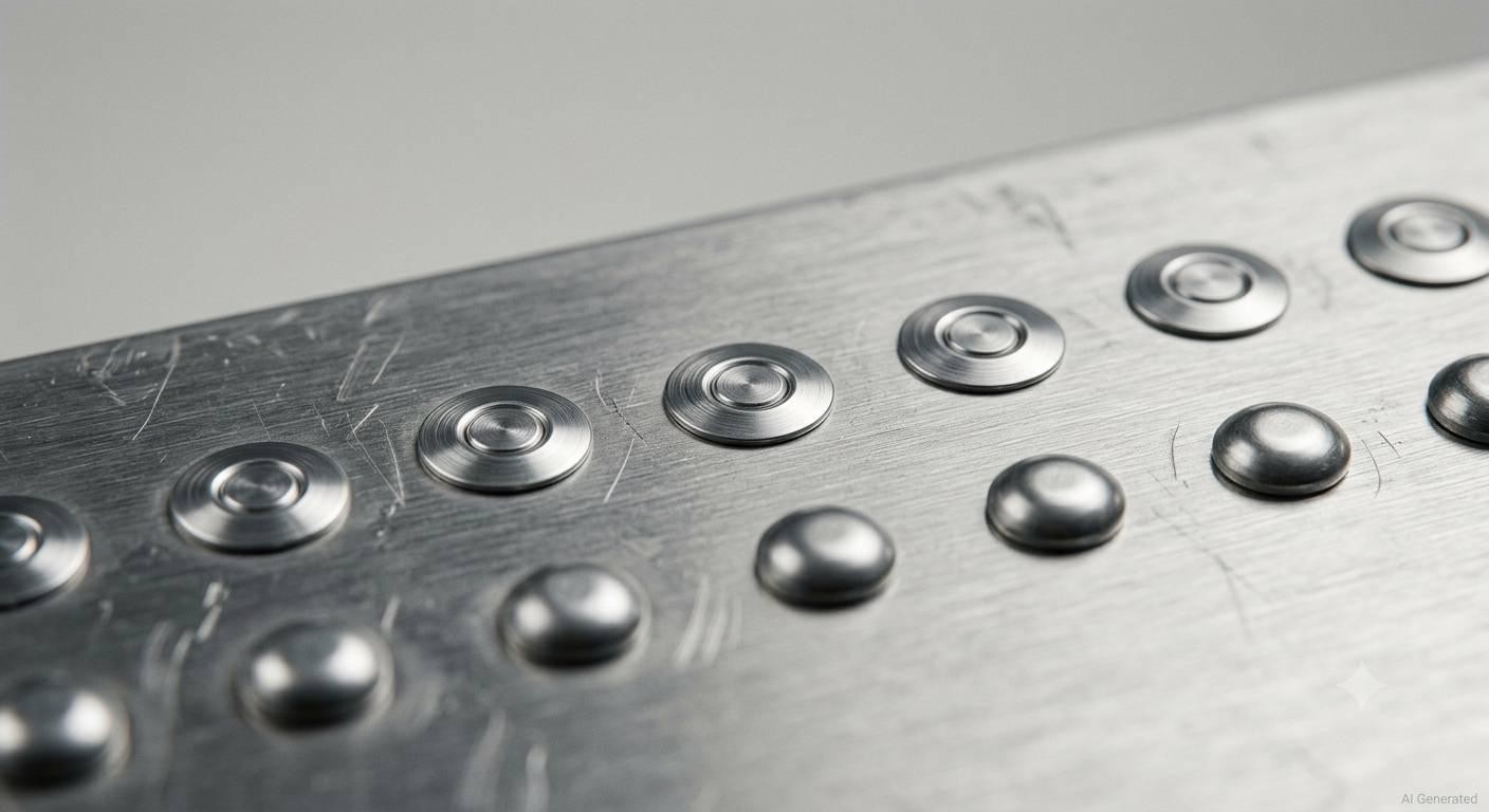
Solid rivets
Solid rivets remain one of the strongest traditional rivet types for structural applications. A solid rivet consists of a fully solid cylindrical shank with a preformed head, installed by inserting it through the workpiece and upsetting the tail with a rivet hammer or pneumatic rivet gun against a bucking bar held on the opposite side.
Solid rivets require access to both sides of the joint, one side for the installation tool and one side for the bucking bar that supports the tail during upsetting. This two-sided access requirement limits where solid rivets can be used, but where access permits, solid rivets produce the strongest, most reliable joints of all rivet types.
Aerospace structures, aircraft fuselages, wing panels, and control surfaces use solid rivets as the primary structural fastener. The 2117-T4 and 2024-T4 aluminum solid rivets are the most common in aerospace applications. Solid steel rivets appear in heavy structural applications including bridges, heavy equipment frames, and structural steel connections where high shear strength is the primary requirement.
2. Blind (POP) Rivets
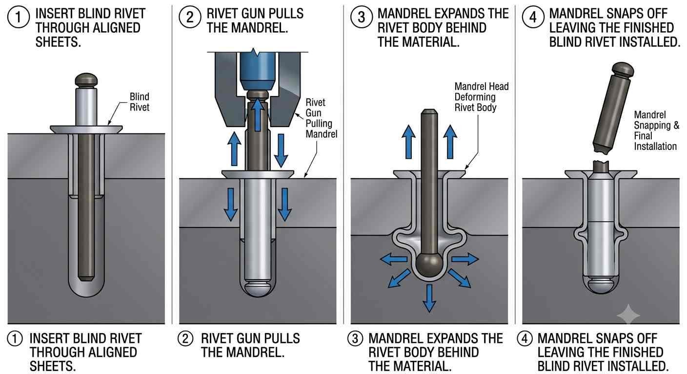
Blind rivets
Blind rivets are among the most widely used rivets in general manufacturing and assembly because they install from one side only. The "blind" side doesn't need to be accessible. A blind rivet consists of a hollow rivet body and a mandrel (the pull stem) that runs through the center. The installation tool grips the mandrel and pulls it while the rivet body is held against the near side of the joint. The pulling action draws the mandrel head into the rivet body, expanding it against the far side of the joint, and when the mandrel reaches its break point, it snaps off, leaving the expanded rivet body in place.
These rivet types are sometimes called POP rivets, a registered trademark that has become widely used as a generic term for blind rivets, similar to how "Velcro" describes hook-and-loop fasteners. Uses for rivets of the blind type span virtually every industry: electronics enclosures, automotive body panels, HVAC ductwork, signage, trailer bodies, and marine fittings all use blind rivets extensively.
Different kinds of blind rivets extend the basic mechanism for specific applications. Large-flange blind rivets distribute the clamping load over a larger area for thin or soft materials. Sealed blind rivets have a closed end that prevents fluid passage through the rivet hole. Multi-grip blind rivets accommodate a wider range of combined material thicknesses without requiring different rivet lengths.
3. Semi-Tubular Rivets
Semi-tubular rivets have a partial hole in the tail end. The hole depth is less than the shank diameter, creating a partially hollow structure that splits and rolls outward during installation rather than upsetting as a solid mass. The result is a large, consistent mushroom head on the tail side that spreads the clamping load over a large area.
These rivets require significantly less installation force than solid rivets. The semi-tubular structure curls rather than deforming solid material, which makes them suitable for assembling materials that would be damaged by the force required for solid rivet installation. Leather, fabric, plastic panels, and thin-gauge sheet metal all use semi-tubular rivets for this reason.
Semi-tubular rivets are common in hinge assembly, bag hardware, belt fastening, and light-duty sheet metal fabrication where appearance and low installation force matter alongside joint strength.
4. Tubular Rivets
Tubular rivets are fully hollow through the entire shank length. The hollow tube rolls outward during installation to form a curled head on the tail side, similar to semi-tubular types but with an even larger area of deformation and even lower installation force requirement.
These rivets appear in applications where the appearance of the joint is important. The curled head on the tail side is more uniform and visually consistent than an upset solid rivet tail. Clothing hardware, shoes, leather goods, sporting equipment, and decorative assemblies use tubular rivets where aesthetics alongside mechanical connection matter.
5. Drive Rivets
Drive rivets have a short pin protruding from the head side rather than requiring installation from the tail side. The pin is driven into the rivet with a hammer, forcing the tail to expand against the far side of the joint in one direction of installation force. No tool on the opposite side is required.
Uses for drive rivets include attaching nameplates, trim panels, and lightweight decorative components where access is from one side and installation speed matters more than high joint strength. Drive rivets are among the simplest rivet types to install. A hammer is sufficient, which makes them common in field repair and assembly applications where pneumatic tools aren't available.
6. Split Rivets
Split rivets (also called bifurcated rivets) have a split shank that spreads outward during installation, with the two prongs bending back against the far face of the material to create the locking effect. These rivets pierce thin soft materials without pre-drilled holes in some applications, making them one of the few rivet types that can be used without hole preparation.
Uses for split rivets include bookbinding, leather assembly, soft goods manufacture, and fiber-based material joining where the soft material accommodates the spreading prongs without cracking. Split rivets aren't appropriate for structural metal joining. Their strength in metal applications is limited by the thin prong cross-sections, but for the textile, leather, and paper applications they're designed for, no other rivet type installs as efficiently.
Rivet Head Styles
Not all rivets with the same installation method have the same head shape. Head style affects how the fastener sits on the surface, how the load is distributed, and whether a flush finish is required. Engineering drawings usually specify both the rivet type and the head style.
1. Round Head
Round head rivets leave a raised profile after installation. The larger bearing surface helps distribute the clamping load, making this head style suitable for general structural assemblies where surface flushness is not required.
2. Universal Head
Universal heads combine a relatively low profile with good mechanical strength. They are widely specified in aerospace standards because they provide adequate bearing area while reducing protrusion compared with traditional round heads.
3. Countersunk Head
Countersunk rivets sit flush with the surrounding surface after installation. They are selected where aerodynamic performance, sealing surfaces, or component clearance would be affected by a protruding head. Because the workpiece must be countersunk before installation, this design removes some parent material and should only be used where a flush surface is necessary.
3. Flat Head
Flat head rivets provide a broad bearing surface on thin materials or soft substrates where reducing local bearing stress is more important than achieving a flush finish. They are often specified when the workpiece cannot support concentrated loading around the rivet hole.
Comparing Different Rivet Types
The table compares rivet construction types. Head style should be selected separately according to surface requirements and drawing specifications.
| Rivet Type | Access Required | Strength | Best Materials | Typical Uses | Installation Tool |
|---|---|---|---|---|---|
| Solid | Both sides | Highest | Metal, composites | Aerospace, bridges, structural | Rivet gun + bucking bar |
| Blind (POP) | One side only | Medium-High | Metal, plastic, composites | General manufacturing, enclosures | Rivet gun (hand or pneumatic) |
| Semi-Tubular | Both sides | Medium | Thin metal, leather, plastic | Hinges, hardware, light assemblies | Press or rivet setter |
| Tubular | Both sides | Low-Medium | Leather, soft materials | Clothing, decorative hardware | Press |
| Drive | One side | Low-Medium | Thin panels, trim | Nameplates, trim panels | Hammer |
| Split | One side | Low | Leather, fabric, paper | Bookbinding, soft goods | Press or hand set |
Solid rivets remain one of the strongest choices for structural metal joints. The most versatile rivet types for one-sided installation are blind rivets. The lowest-force installation rivets for soft materials are drive, split, and tubular variants. Matching the rivet type to the structural requirement, material, and access condition is the core of rivet selection.
Selecting the correct rivet is only half of the equation. Hole diameter, spacing, edge distance, and material thickness all determine how well the finished joint performs. JLCCNC manufactures precision CNC and sheet metal components with accurate hole locations and tight tolerances to ensure reliable riveted assemblies. Upload your CAD files today for a free engineering review and quote.
Precision CNC Machining Service
Professional manufacturing, fast turnaround, and quality assurance.
Rivet Materials
The material of a rivet affects its strength, corrosion resistance, compatibility with base materials, and cost. Rivet materials need to be appropriate for the base materials being joined to avoid galvanic corrosion, dissimilar metals in electrical contact with an electrolyte (moisture, salt) create galvanic cells that corrode the less noble metal.
Aluminum Rivets
Aluminum is the most common rivet material in aerospace and general sheet metal applications. Aluminum rivets are lightweight, corrosion-resistant, and compatible with aluminum base materials. The galvanic pairing of an aluminum rivet to aluminum sheet significantly reduces galvanic corrosion risk.
Common aluminum rivet alloys: 2117-T4 (the most common aerospace solid rivet, good formability), 2024-T4 (stronger, used where higher shear strength is needed), 5056 (for joining magnesium alloys), and 6061 (general-purpose aluminum rivet material).
Steel Rivets
Steel rivets provide higher strength than aluminum for structural applications. Carbon steel rivets appear in heavy structural construction, heavy equipment, and applications where the high shear and tensile strength of steel is required. Steel rivets corrode in moisture unless protected by plating (zinc, cadmium), painting, or the use of stainless steel instead.
Uses for steel rivets include structural steel connections, heavy equipment frames, and infrastructure applications where aluminum's strength isn't sufficient.
Stainless Steel Rivets
Stainless steel rivets combine steel's strength with corrosion resistance, appropriate for marine, food processing, outdoor, and chemical environment applications where carbon steel would corrode. 304 and 316 stainless are the most common rivet alloys, with 316 providing better chloride resistance for marine applications.
Different kinds of stainless rivets include both solid and blind types, making stainless available for the full range of uses for rivets that require corrosion resistance alongside structural performance.
Copper and Brass Rivets
Copper and brass rivets are used in applications where electrical conductivity, appearance, or corrosion resistance in specific environments are required. Copper rivets appear in leather goods and traditional craft applications. Brass rivets are used in electronics, marine hardware, and decorative assemblies where their appearance and moderate corrosion resistance justify their higher cost compared to aluminum rivets.
Common Rivet Applications
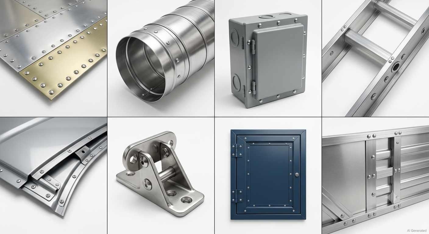
Common applications of rivet
Sheet Metal Assemblies
Sheet metal fabrication uses blind rivets more than any other rivet category because sheet metal assemblies frequently have one face permanently enclosed after assembly, making two-sided rivet installation impractical. HVAC ductwork, electronic enclosures, appliance housings, and automotive body panels all use blind rivets for fast, reliable joining of sheet metal panels with one-sided access.
Semi-tubular rivets appear in sheet metal hinge assemblies where the low installation force preserves the hinge geometry during riveting.
Aerospace Structures
Aerospace is the primary application for solid rivets, particularly aluminum solid rivets in the 2117 and 2024 alloy grades. Aircraft fuselages, wing skins, bulkheads, and control surfaces use solid rivets as primary structural fasteners. Solid rivets are widely used in aerospace structures because properly installed joints provide reliable fatigue performance under repeated loading.
Different kinds of specialty aerospace rivets include countersunk head variants that sit flush with the skin surface to minimize aerodynamic drag, and high-strength titanium rivets for applications where aluminum rivet strength isn't sufficient.
Automotive Components
Automotive manufacturing uses multiple rivets across different joining applications. Self-piercing rivets, a specialized category that punches through the near layer and locks into the far layer without a pre-drilled hole, are widely used in modern automotive body assembly, particularly on high-volume production lines, where production speed is essential. Blind rivets join trim panels, interior components, and assemblies where access to the rear face is restricted. Structural rivets join aluminum body structures in vehicles where welding aluminum is less practical than in steel body construction.
Electronics and Enclosures
Electronic enclosures, computer chassis, server racks, and equipment panels use blind rivets extensively. The uses for rivets in electronics assembly include panel attachment, hinge joining, PCB mounting bracket assembly, and rack chassis construction, applications where blind installation is required and where the vibration resistance of rivet types outperforms screws in high-vibration environments.
How to Choose the Right Rivet
Base Material Compatibility
The rivet material must be galvanically compatible with the base materials. Using steel rivets in aluminum sheet creates a galvanic couple that corrodes the aluminum around the rivet hole, a common and serious mistake in riveted assembly. A practical guideline is to match rivet material to base material wherever possible, or choose the more noble metal of the two when dissimilar materials must be joined.
Joint Thickness and Grip Range
Every rivet type has a grip range, the total thickness of material it can clamp effectively. A rivet specified for a 3-6mm grip range won't form a proper joint in material only 2mm thick (too little material for the tail to compress against) or in 10mm thick material (the mandrel breaks before sufficient deformation occurs in blind rivets, or insufficient tail protrudes for solid rivets).
Rivet types and identification on engineering drawings always include the grip range specification. Verify actual material stack thickness before selecting the rivet length within the appropriate grip range.
Required Strength
Different kinds of rivets have different shear strength and tensile strength values depending on rivet type, diameter, and material. For structural applications, specify the required joint strength, calculate the number of rivets needed based on published strength values for the selected rivet type and diameter, and confirm the calculation against the joint geometry.
For non-structural joining, trim attachment, decorative hardware, and lightweight panel assembly, strength calculation is less critical than for load-carrying joints, and the installation practicality factors (access, speed, tooling) often drive rivet type selection.
Installation Access
This factor determines which rivet types are viable before any other consideration. If both sides of the joint are accessible throughout the assembly process, all rivet types are candidates. If one side is permanently enclosed, blind rivets (and drive rivet types for light applications) are the only options. Map access conditions at every rivet location before specifying rivet types.
Design Guidelines for Riveted Parts
A reliable riveted assembly starts with the part design. The rivet itself only transfers load after the surrounding material, hole geometry, and component alignment meet the required conditions. Poor hole placement or unsuitable part geometry can create assembly problems even when the correct rivet type is selected.
Hole Size and Position
The rivet hole should provide enough clearance for installation while maintaining proper support around the rivet shank. An oversized hole allows excessive movement between assembled parts and reduces joint consistency. A hole that is too small can prevent proper installation or damage the rivet during insertion.
Hole position is equally important, especially when multiple sheet metal components are assembled together. Misaligned holes can force parts into position during riveting, which may introduce unwanted stress or distort thin panels.
For CNC machined parts, accurate hole locations help maintain alignment between mating components. In sheet metal fabrication, hole positions should also account for bending operations because forming processes can change the final location of nearby features.
Edge Distance and Material Thickness
Rivet holes placed too close to an edge can weaken the surrounding material. During installation, the expansion force from the rivet may deform the edge or cause local cracking in thin sheets.
Material thickness also affects rivet selection. A rivet that works well for a thin aluminum panel may not provide sufficient grip for a thicker assembly. The combined thickness of all joined components should be checked against the rivet grip range before production.
For bent sheet metal parts, avoid placing rivet holes too close to bend lines. The available flange width must leave enough space for both forming and riveting operations.
Tolerance and Assembly Fit
Riveted assemblies usually depend on consistent hole location rather than extremely tight dimensional tolerances on every feature. The critical requirement is that mating parts align correctly during assembly.
When parts are produced by CNC machining or sheet metal processes, controlling hole position, diameter consistency, and burr condition helps prevent installation issues. Burrs around punched or drilled holes can interfere with rivet seating and may create uneven contact between components.
Consider the Assembly Sequence
The installation method should be considered before finalizing the design. A blind rivet may be suitable when the rear side of the assembly becomes inaccessible, while solid rivets require access for installation tooling.
Designers should also consider how parts will be positioned before riveting. Features such as locating holes, tabs, or temporary alignment points can simplify assembly and reduce variation during production.
For CNC machined and sheet metal components, rivet design is closely connected with manufacturing processes. Hole placement, material thickness, and access conditions should be reviewed together before parts move into production.
Manufacturing Considerations for Riveted Parts
Riveted joints depend on accurate hole geometry and proper alignment between assembled components. During CNC machining and sheet metal fabrication, hole size, position, and edge quality should be controlled according to the selected rivet specification. For CNC machined and sheet metal parts, JLCCNC supports riveted assembly requirements by maintaining accurate hole positions, controlled edge quality, and consistent part dimensions during fabrication.
Hole Size and Position Accuracy
The rivet hole diameter should match the recommended clearance for the selected rivet. Oversized holes can reduce joint strength by allowing excessive movement, while undersized holes may prevent proper installation.
For CNC-machined or sheet metal parts, maintaining consistent hole position is also important because misaligned holes can create assembly difficulties and uneven load distribution.
For example, a bent aluminum enclosure assembled with blind rivets requires accurate hole positioning after forming. If holes are too close to bends, assembly alignment may become difficult after sheet deformation.
Edge Quality and Burr Control
Burrs and damaged hole edges can interfere with rivet installation and create stress concentration areas around the joint. Deburring after drilling, punching, or machining helps ensure proper rivet seating and improves assembly consistency.
Precision CNC Machining Service
Professional manufacturing, fast turnaround, and quality assurance.
How Rivets Are Installed
Manual Installation
Solid rivets install manually with a rivet hammer and bucking bar. One person holds the bucking bar against the tail, and another drives the head with the rivet hammer. For small numbers of solid rivets in field repairs or low-volume assembly, manual installation is practical. The technique requires skill to produce consistent joints. Overtapping distorts the rivet head, and undertapping leaves insufficient material upset.
Hand-operated blind rivet tools grip the mandrel and draw it through the rivet body with a lever action. Blind rivets installed with hand tools work well for low-volume applications and field use where pneumatic tools aren't available.
Pneumatic Riveting
Pneumatic rivet guns dramatically increase installation speed for all rivet types that can accommodate them. Pneumatic solid rivet installation uses a rivet gun that delivers controlled hammer blows at high frequency against the rivet head while a bucking bar supports the tail. The main advantage is installation speed. A skilled operator with a pneumatic rivet gun and bucking bar installs solid rivets 5-10x faster than manual hammering.
Pneumatic blind rivet pullers install blind rivets faster and more consistently than hand tools, with the pneumatic action ensuring sufficient mandrel pull force regardless of operator technique.
Automated Riveting
High-volume production, particularly aerospace manufacturing, uses robotic riveting systems that drill holes, insert rivets, and upset them automatically in a single programmed operation. Automated riveting provides repeatability that manual installation can't match, eliminates variation in operator technique, and enables installation at locations that manual access would make impractical in a confined fuselage interior.
Common Riveting Mistakes
Selecting the Wrong Rivet Material
Using steel rivets in aluminum sheet, or aluminum rivets in stainless steel structures, creates galvanic corrosion at every rivet location. This is one of the most expensive and difficult-to-repair riveting mistakes because the corrosion isn't visible until it's advanced, and repair requires drilling out every rivet and assessing the surrounding material for corrosion damage.
Using the Wrong Grip Length
Under-length rivets don't protrude enough tail material to form a proper second head. Over-length rivets have excess tail that either folds unpredictably during upsetting (in solid rivets) or causes mandrel break before full expansion is achieved (in blind rivets). Both conditions produce joints with reduced clamping force and lower actual strength than the rivet specification assumes.
Poor Hole Preparation
Holes that are too large for the rivet diameter allow the rivet shank to shift before and during installation, reducing joint precision and reducing shear strength because the rivet body doesn't fit snugly against the hole wall. Holes with burrs or torn edges prevent proper seating of the rivet head and create stress concentration points at the joint interface. Deburr all holes and verify diameter against the rivet specification before installation.
Incorrect Installation Force
Too little installation force on solid rivets leaves the tail under-upset, the rivet body hasn't expanded fully against the hole wall and the joint has lower clamping force than designed. Too much force distorts the rivet head or, in soft materials, pulls the head through the workpiece. Calibrated pneumatic rivet guns and dies set for the specific rivet type and diameter eliminate this variable from the installation process.
FAQs About Rivets
Q: What are the different types of rivets?
The main types of rivets are solid rivets (strongest, require two-sided access), blind or POP rivets (one-sided installation, most common in general manufacturing), semi-tubular rivets (partial hollow tail, lower installation force), tubular rivets (fully hollow, rolls outward on installation), drive rivets (pin-driven, single-sided), and split rivets (spreading prongs, for soft materials). Each of these rivets is designed for specific material combinations, access conditions, and strength requirements.
Q: What is the difference between solid and blind rivets?
Solid rivets require access to both sides of the joint, a bucking bar on the tail side during installation, and produce the highest-strength joints. Blind rivets install from one side only, with the mandrel mechanism expanding the rivet body against the far side without requiring rear access. Solid rivets are stronger, and blind rivets are more versatile for assemblies where rear access isn't possible.
Q: Which rivet is the strongest?
Solid rivets generally provide high joint strength and are widely used for structural applications, which is why they're the primary structural fastener in aerospace structures. Among blind rivets, structural blind rivets with steel mandrels approach solid rivet strength for the materials they're designed for.
Q: What are blind rivets used for?
Uses for blind rivets include any riveted joint where the back face of the assembly is enclosed or inaccessible, electronics enclosures, automotive body panels, HVAC ductwork, trailer bodies, and marine fittings. Blind rivets are also faster to install in open assemblies than solid rivets, making them common in high-volume manufacturing even where rear access technically exists.
Q: How do I choose the right rivet?
Select rivet types based on four factors: base material compatibility (match materials to avoid galvanic corrosion), installation access (one-sided or two-sided), joint thickness and grip range (verify the rivet length covers actual stack thickness), and required strength (calculate joint load against the rivet's rated shear strength). Rivet types and identification data from manufacturer specifications provide all the information needed for a complete selection.
Q: Can aluminum rivets be used with steel?
Using aluminum rivets with steel base material creates a galvanic couple that corrodes the aluminum rivet over time when moisture is present. For joining aluminum to steel, use appropriate isolation methods, coatings, or compatible fastener systems to reduce galvanic corrosion risk.
Q: What is grip range in riveting?
Grip range is the total material thickness range that a specific rivet length can accommodate and still form a proper joint. A blind rivet specified with 3-6mm grip range forms a correct joint when the combined thickness of all materials being joined falls between 3mm and 6mm. Using rivets outside their specified grip range produces undersized tails (insufficient clamping force) or premature mandrel break in blind rivets.
Q: When should rivets be used instead of screws?
Uses for rivets over screws are clearest in vibration environments (rivets do not loosen), thin material assemblies (insufficient thread engagement for screws), applications requiring permanent joints, and one-sided access situations (blind rivets). Different kinds of rivets also assemble faster than screws in high-volume manufacturing, which is why sheet metal assemblies and enclosures frequently specify rivet types rather than threaded fasteners.
Precision CNC Machining Service
Professional manufacturing, fast turnaround, and quality assurance.
Conclusion About Rivet Types
The different types of rivets exist because no single rivet type solves every joining problem. Solid rivets give aerospace structures their structural integrity. Blind rivets make one-sided assembly practical across thousands of manufacturing applications. Semi-tubular and tubular rivets handle thin materials and soft substrates without damage. Drive and split rivet types solve specific access and material challenges that other fasteners can't address.
Understanding rivet types and their identification, along with material selection, grip range, and installation requirements, forms the foundation of proper rivet selection. The wrong rivet type in the right material fails as surely as the right rivet type in the wrong material.
At JLCCNC, CNC machined and sheet metal components for riveted assemblies are produced with hole features matched to rivet specifications, helping ensure proper fit and consistent assembly performance. Upload your files for engineering review and accurate quoting.
Keep Learning
Laser Engraving Aluminum: Marking Methods & Surface Effects
Key Takeaways Laser engraving usually removes base material to create a recess. Laser marking is a broader term that can describe a surface-color change or material removal, so the process name alone does not define the final result. On aluminum, alloy and surface finish affect marking contrast. A light mark on dark anodized aluminum is a common design target, but the actual appearance depends on the finish and laser process. JLCCNC laser marking produces a recessed area 0.03–0.1 mm deep. The result i......
CNC Cutting Fluid: Types, Functions, Applications, and Selection Guide
Key Takeaways Cutting fluid in machining performs four functions simultaneously: cooling the tool and workpiece, lubricating the tool-chip interface to reduce friction, carrying chips away from the cut zone, and protecting machined surfaces from corrosion between operations. Different machining operations need different fluid priorities: high-speed aluminum milling may need adhesion control and chip evacuation, threading and tapping need strong lubrication, and grinding requires both cooling and fine ......
Blind Hole Machining Guide: What Is a Blind Hole, Types of Holes, and Tapping Tips
What Is a Blind Hole? Types of Holes and CNC Hole Machining Explained In CNC machining, few operations challenge process control and tool stability as much as blind hole machining. A blind hole is a hole that terminates at a defined internal depth rather than breaking through the opposite surface. Because the cavity is enclosed at the bottom, chip evacuation, thermal behavior, tool wear, and dimensional accuracy become far more difficult to manage compared to through-hole machining. These constraints ......
Rake Angle in Machining: Machinists’ Guide to Perfect Cuts
What is Rake Angle? (minaprem) If you've ever stood in front of a CNC machine or a manual lathe, you know that the cutting tool's geometry isn't just some arbitrary design. Every angle, edge, and surface has a job to do, and one of the most important of those is the rake angle. We've been running machines long enough to know that rake angle can make or break your surface finish, tool life, and machining efficiency. In this guide, we're going to walk you through what rake angle is, how it works, and ho......
Sheet Metal vs CNC Machining: A Guide to Choosing the Right Method for Your Metal Parts
Quick Answer: Choose sheet metal for uniform-thickness enclosures, panels, and formed brackets when bends and production volume support lower unit cost. Choose CNC machining for variable wall thickness, precision bores, tight feature relationships, and complex 3D geometry. Use a hybrid design when a formed structure needs precision-machined interfaces. A quote comes back for a bracket, and it's priced as a CNC part — machined from solid aluminum, a few hours of spindle time, a per-part cost that makes......
What Steps Are Taken To Minimize Waste In CNC Machining Processes?
How to Reduce Waste in CNC Machining: 5 Practical Strategies Quick Answer: CNC machining waste is reduced mainly through DFM, near-net stock, efficient toolpaths, preventive tool maintenance, and alloy-segregated recycling. The biggest gains usually come before cutting: reduce unnecessary material removal and prevent scrap or rework. Every CNC-machined part starts as more material than it ends up being. A pocket gets milled out, a profile gets cut away, a boss gets faced down to size — and all of that......