Spotface vs Counterbore: Differences, Applications & Selection Guide
17 min
- What Are Spotfaces and Counterbores?
- Spotface vs Counterbore: Key Differences
- When to Use a Spotface
- When to Use a Counterbore
- Practical Engineering Examples
- How Spotfaces and Counterbores Are Machined
- Design Guidelines
- Common Design Mistakes
- Choosing Between a Spotface and a Counterbore
- FAQs About Spotfaces and Counterbores
Quick Comparison Between Spotface and Counterbore
Spotfaces and counterbores are both machined features around holes. A spotface creates a flat seating surface for bolts or washers, while a counterbore creates a recessed cavity that allows screw heads to sit flush or below the surface.
The table below provides a simple comparison of spotface and counterbore features.
| Feature | Spotface | Counterbore |
|---|---|---|
| Primary purpose | Creates a flat seating surface | Creates a flat recess for a fastener head |
| Machining depth | Shallow | Deeper than a spotface |
| Material removal | Removes only the minimum material needed | Removes enough material to accommodate the fastener head |
| Fastener position | Fastener head remains above the surface | Fastener head is recessed flush with or below the surface |
| Common fasteners | Bolts, nuts, washers | Socket head cap screws, hex socket screws |
| Typical applications | Castings, forgings, rough surfaces | Precision assemblies, machine components |
| Machining time | Shorter | Longer due to greater cutting depth |
| Typical callout | Spotface (SF) | Counterbore (⌴) |
Many engineering drawings use the same counterbore symbol with the abbreviation SF to indicate that only a shallow spotface is required.
A drilled hole is not always enough for a proper fastener fit. The surface around the hole may be uneven, especially on cast or rough-machined parts, or the screw head may need to sit below the part surface. In these cases, a spotface or counterbore is machined around the hole to create the required seating area.
A spotface removes a small amount of material to create a flat seating surface on rough, curved, cast, and forged parts. By comparison, a counterbore machines a larger cylindrical recess so a socket head screw fits inside the part instead of remaining above the surface.
Although both features are often machined around drilled holes, they are specified for different assembly needs.
This guide will cover:
- The difference between a spotface and a counterbore.
- How both features are machined in CNC manufacturing.
- Common applications for each hole feature.
- How to choose the right feature for your design.
- Engineering drawings, symbols, and dimension callouts.
- Practical design and manufacturing considerations.
What Are Spotfaces and Counterbores?
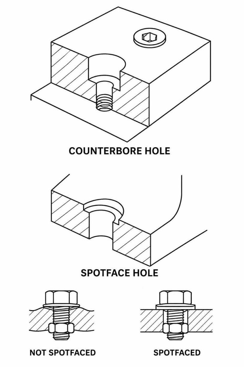
Spotface vs Counterbore - Fundamentals of Machine Tools
The drilled hole is only one part of the finished feature. If a washer, bolt head, or nut needs a flat contact area, a spotface is machined around the hole. If the screw head has to fit below the top face, the same hole receives a counterbore instead. The hole stays the same, but the machining around it changes to suit the assembly.
What Is a Spotface?
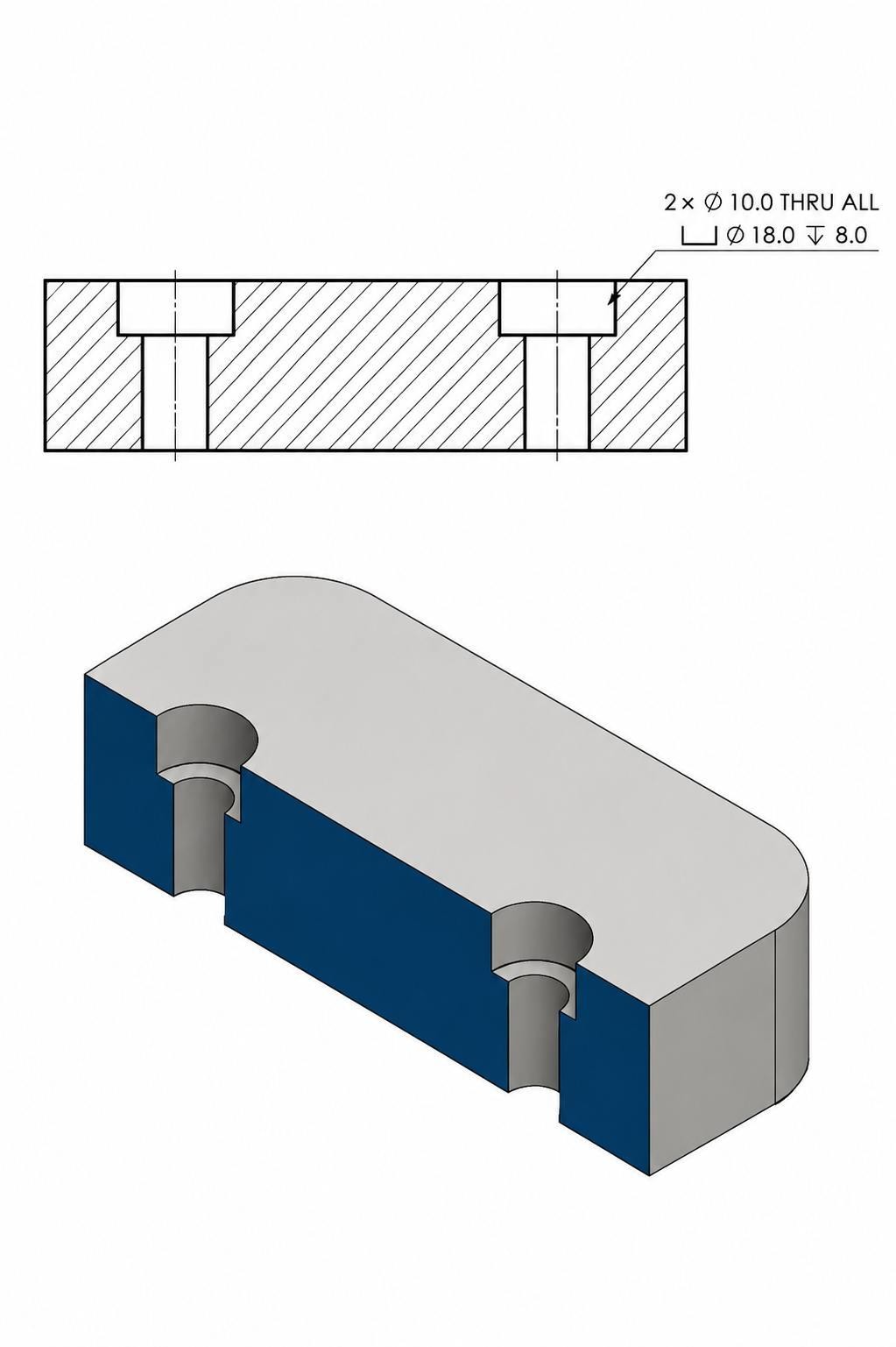
Spotface hole
A spotface is a shallow machined surface around a hole. Its purpose is to provide a flat area for a bolt head, nut, washer, spacer, or another mating component.
Spotfaces are commonly added to castings, forgings, and welded parts because these surfaces are rarely flat enough for direct assembly. Instead of machining the entire face of the component, only a small circular area is cut around the hole. This reduces machining while providing a proper seating surface for the fastener.
What Is a Counterbore?
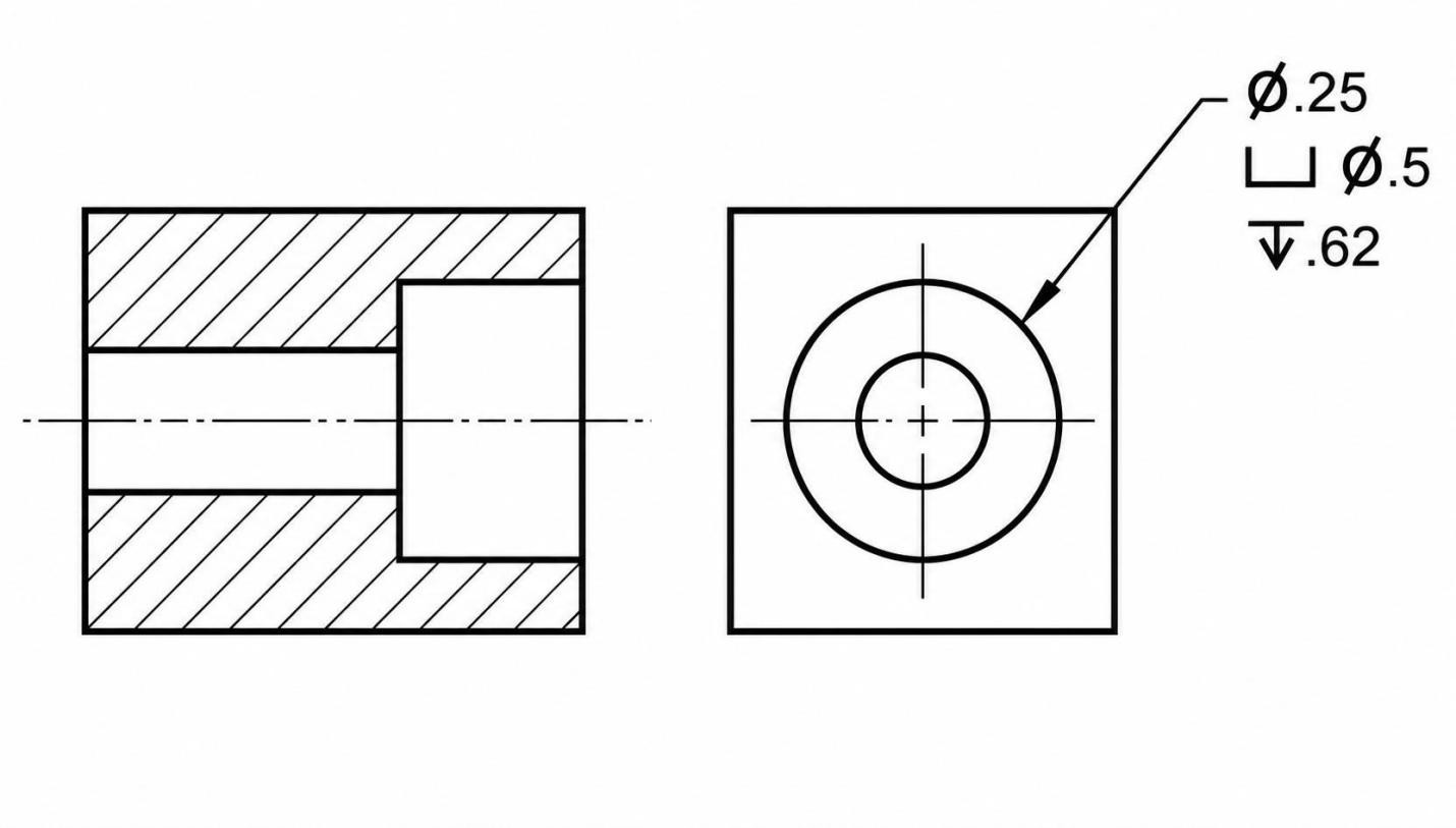
Counterbore hole diameter - Engineering Essentials
A counterbore is a cylindrical recess machined above a drilled hole. The recess is sized to match the diameter and height of the fastener head.
This feature is commonly specified for socket head cap screws because the screw head fits inside the recess instead of projecting above the surface. It is also used where another component passes over the fastener, making a flush surface necessary for assembly.
Why Are These Hole Features Used?
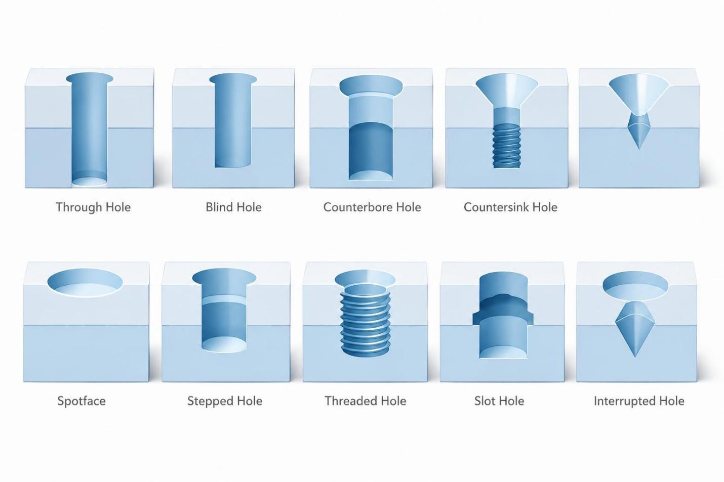
Types of holes in engineering - MinHe
A drilled hole defines the fastener location, but the area around the hole is often just as important during assembly. A spotface is added if the bolt head, washer, or nut needs a flat surface to sit against instead of the original cast, forged, and uneven face.
A counterbore is selected if the screw head cannot project above the component surface. The machined recess accommodates the fastener head, leaving the outer face unobstructed for mating components, covers, guide plates, and similar parts.

Precision CNC Machining Service
Professional manufacturing, fast turnaround, and quality assurance.
Spotface vs Counterbore: Key Differences
A spotface and a counterbore may look similar on a drawing, but they are specified for different machining requirements. The difference is not limited to the feature depth. It also changes the amount of material removed, the fastener position, and the machining operation used to produce the feature.
Comparison Table
| Parameter | Spotface | Counterbore |
|---|---|---|
| Typical depth | 0.2 to 2.0 mm | 3 to 12 mm (depends on fastener size) |
| Diameter | Slightly larger than the seating area | Sized to fit the fastener head |
| Side wall | Minimal due to shallow depth | Straight cylindrical wall |
| Bottom surface | Flat | Flat |
| Depth control | Less critical | Controlled to match fastener head height |
| Material removal | Low | Moderate to high |
| Machining cycle | Single shallow cut | Multiple cuts may be required |
| Fastener head position | Above the part surface | Flush with or below the surface |
| Common manufacturing process | Face milling, spotfacing tool | Counterbore cutter, end mill |
| Typical components | Castings, forged parts, welded structures | Fixture plates, machine frames, gearbox housings |
Geometry and Depth
The geometry of a spotface is intentionally shallow. Only enough material is removed to produce a flat contact surface around the hole. The surrounding part geometry remains almost unchanged.
A counterbore extends farther into the material and forms a cylindrical pocket. Its diameter and depth are selected to match the specified fastener. Because the pocket becomes part of the assembly, both dimensions are normally controlled on the drawing.
Fastener Seating and Bearing Surface
Spotface: The bolt head, washer, spacer, or nut sits directly on the machined surface instead of the original casting or forging. Only the seating area is machined, while the fastener remains in its normal position above the component.
Counterbore: The fastener head sits inside the machined recess instead of above the component surface. This arrangement leaves the top face clear, which is common on fixture plates, machine bases, covers, and other parts with limited assembly clearance.
Manufacturing and Typical Applications
Spotfaces are commonly used on:
- Cast, forged, and welded parts with rough mounting surfaces.
- Parts that need a flat area for bolts, washers, or nuts.
- Components that need only a shallow cut around the hole.
Counterbores are commonly used on:
- Precision-machined parts made from billet material.
- Fixture plates, machine bases, tooling parts, and housings.
- Assemblies using socket head cap screws with recessed heads.
- Parts that need the screw head below the top surface.
When to Use a Spotface
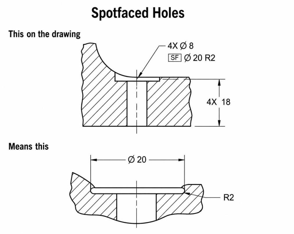
Spotface hole depth - Eng -Tips
A spotface is selected if the fastener needs a flat seating surface but a deep recess is not required. It removes only a small amount of material while preparing the hole for proper assembly.
Uneven Cast or Forged Surfaces
The surfaces around holes drilled in cast and forged parts are likely to be uneven, making it difficult for the fastener to rest properly. A spotface only machines around the hole, leaving the rest of the surface unchanged. This reduces the machining time and provides a flat seating area for the assembly.
Limited Material Thickness
Some parts do not have enough material to machine a deep counterbore without reducing wall thickness. A spotface creates the required seating surface with a shallow cut, leaving most of the original material intact. It is commonly used on thin flanges, covers, and lightweight components where material removal must be kept low.
Creating a Flat Bearing Surface
Fasteners apply the clamping load through the surface beneath the bolt head, washer, or nut. If that surface is rough or uneven, the contact area can become inconsistent during tightening. A spotface provides a smooth and level bearing surface so the fastener seats evenly against the part.
When to Use a Counterbore
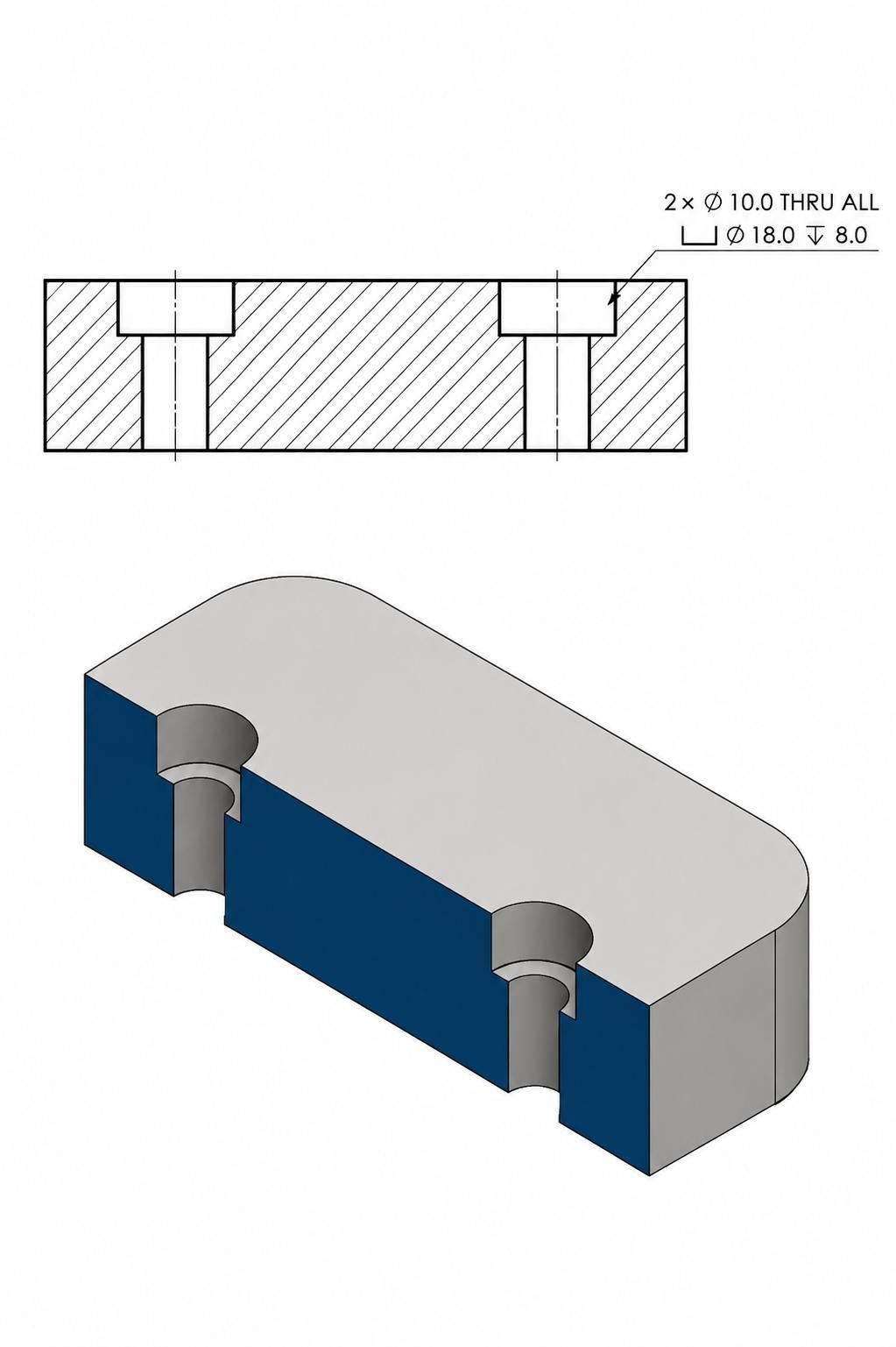
Counterbore hole
A counterbore is specified if the fastener head must fit within the component instead of remaining above the surface. The required depth and diameter are normally selected according to the fastener standard and the available material thickness.
Recessing Socket Head Screws
Socket head cap screws are commonly installed in counterbores because the recess matches the head diameter and height specified by standards such as ISO 4762 and ASME B18.3.
Seating the screw inside the component eliminates head projection, which is often specified on machine bases, fixture plates, and precision tooling.
This arrangement also allows adjacent components to move past the fastener without requiring additional clearance.
Flush Component Assembly
A projecting fastener head can prevent two machined surfaces from fitting together as shown on the assembly drawing. A counterbore positions the fastener below the top surface, allowing covers, mounting plates, and mating components to contact the part directly. This feature is commonly specified where the assembled height must remain unchanged.
Deep Fastener Seating
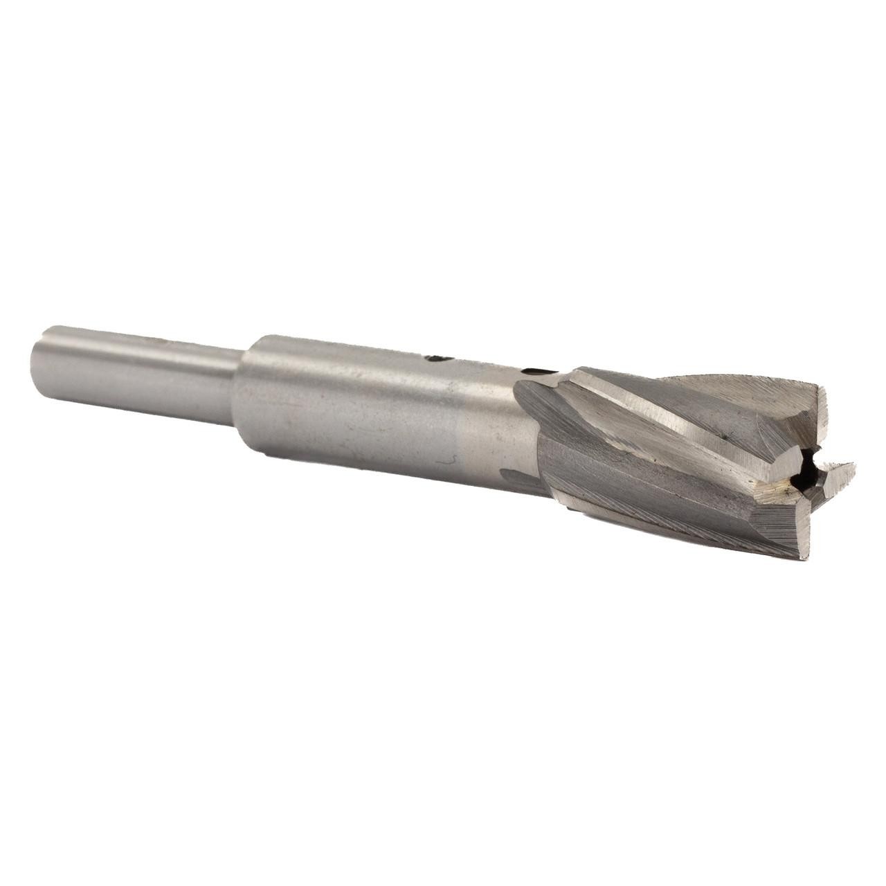
HSS Aircraft Counterbore Shank - Drill & Cutters
Thicker components sometimes require recessed socket head cap screws with taller heads than standard clearance holes can accommodate. A counterbore provides a recess that fully supports the fastener head while maintaining the specified engagement in the threaded hole. This approach is frequently used on structural machine components, tooling blocks, and equipment frames where deeper fastening locations are required.
Practical Engineering Examples
Spotfaces and counterbores are selected according to the assembly drawing, fastener specification, and part geometry. Changing from a bolt-and-washer joint to a recessed socket head screw may require a different machining feature and drawing callout. The examples below show how these features are commonly applied on production components.
Spotface Example on a Cast Housing
A cast gearbox housing uses M12 hex head bolts to secure the top cover. After casting, the mounting flange has a surface variation of approximately 0.5 - 1.5 mm, which is not suitable for direct bolt seating. Instead of face milling the complete flange, a 24 mm diameter spotface is machined around each bolt hole. This provides a flat bearing surface for the washer while removing only a small amount of material from the casting.
Counterbore Example for a Socket Head Cap Screw
A steel fixture plate is assembled with ISO 4762 M8 socket head cap screws. Each clearance hole includes a Ø13 mm counterbore with a depth of 8 mm, allowing the screw head to sit below the top surface. This prevents the workpiece and clamping system from contacting the fastener during CNC machining and leaves the fixture surface completely clear.
Comparing Two Design Solutions
Consider two mounting plates with identical Ø10.5 mm clearance holes for M10 fasteners. The first plate uses a standard hex bolt with a washer, so only a 20 mm spotfacing is required to provide a flat seating surface. The second plate uses an M10 socket head cap screw that must remain below the surface because another component slides across the plate. In this case, the drawing specifies a counterbore sized to the screw head. The hole diameter stays the same, but the machining operation changes because the assembly requirements are different.
How Spotfaces and Counterbores Are Machined
A spotface and a counterbore are usually machined after the hole reaches its finished diameter. The selected cutter, machining sequence, and inspection method depend on the feature specified on the drawing.
Common Machining Methods
Spotfaces are commonly produced with a pilot spotfacing cutter because the pilot keeps the cutter centred inside the drilled hole. Counterbores are usually machined with a pilot counterbore cutter. Flat end mills are also used on CNC machines, particularly for non-standard diameters.
Castings and forgings are often machined on vertical machining centres, while smaller repair jobs may be completed on manual milling machines. Standard counterbores normally follow the dimensions of the selected fastener, reducing the need for custom tooling.
CNC Machining Process
The drilled hole establishes the centre location, so no additional positioning is required before machining the recess. The machine removes material only within the specified diameter, leaving the surrounding surface unchanged. Spotfaces are often completed because only a small amount of material is removed. Counterbores may require multiple passes when machining large diameters, greater depths, or hard materials.
Inspection of Diameter, Depth, and Flatness
The recess diameter is measured because it determines whether the selected fastener will seat correctly. The machined depth is checked against the drawing, particularly for counterbores where the screw head position is specified. The bottom face is inspected to confirm full contact beneath the fastener head instead of partial contact around the edge. Surface burrs are removed before inspection because they can affect both dimensional measurements and assembly.
Design Guidelines
Designers specify spotface and counterbore dimensions directly on drawings based on the selected fastener and available material thickness. The selected values are based on the fastener size, the available material around the hole, and the function of the assembled component. A well-defined drawing reduces machining changes and avoids assembly issues later in production.
Match Hole Features to Fastener Types
The fastener usually determines which hole feature is added to the drawing. Hex bolts and washers are commonly paired with spotfaces because they only require a flat seating surface. Socket head cap screws are normally paired with counterbores since the recess is sized to match the screw head. This keeps the hole feature consistent with the selected fastening method.
Specify Functional Dimensions
The dimensions shown on the drawing should correspond to the selected fastener instead of using estimated values. Counterbore diameters and depths are commonly taken from standards such as ISO 4762, DIN 912, and ASME B18.3. Spotface diameters are normally larger than the bearing surface of the bolt head or washer so the entire contact area remains supported after assembly.
Maintain Adequate Bearing Surface
The seating surface should fully support the fastener during tightening. If the spotface diameter is too small, part of the washer or bolt head may extend beyond the machined surface. Likewise, an oversized counterbore removes additional material without providing any assembly benefit. The bearing surface is therefore selected to provide full contact while preserving enough material around the hole.
Follow Drawing Standards
Engineering drawings define spotfaces and counterbores with standard symbols, dimensions, and tolerances so every department interprets the feature in the same way. Standards such as ASME Y14.5 and ISO 1101 define dimensioning and geometric tolerances, while fastener standards define the corresponding counterbore sizes. Using these references keeps the machined feature compatible with standard fasteners and simplifies inspection after machining.
Common Design Mistakes
Most design issues appear during drawing review because the hole feature does not match the fastener, the available material, or the surrounding geometry. These problems often require drawing revisions before machining starts.
Confusing Spotfaces with Counterbores
A drawing may specify a spotface even though the assembly uses socket head cap screws. During assembly, the screw head remains above the surface because there is no recess for it. In the opposite case, a counterbore is added for a standard hex bolt, increasing machining time without changing the assembly.
Incorrect Drawing Callouts
Some drawings define the counterbore diameter but omit its depth. Others show the depth but do not identify the fastener standard. Without both values, the machinist cannot determine the correct recess size because M8 ISO 4762 and M8 DIN 7984 screws use different head heights.
Excessive Machining Depth
A deep counterbore may leave very little material below the recess, especially on thin covers and mounting plates. This becomes a common issue if the counterbore depth is copied from another drawing without checking the current part thickness. Drawing review normally checks the remaining material before machining is approved.
Selecting an Incompatible Fastener
Counterbores are produced to match standard fastener dimensions. If the design changes from an ISO socket head cap screw to a low-head socket screw after the drawing is completed, the existing counterbore may become oversized or too deep. The fastener specification and the counterbore dimensions therefore need to be reviewed together before production begins.
Choosing Between a Spotface and a Counterbore
The final choice depends on the fastener, the part geometry, and the assembly shown on the drawing. If the fastener only needs a flat seating surface, a spotface is usually sufficient. If the fastener head must fit inside the component, a counterbore is the preferred feature.
Selection Checklist
| Design Consideration | Choose Spotface | Choose Counterbore |
|---|---|---|
| Part surface is rough, cast, or forged | ✓ | |
| Flat seating surface is required | ✓ | |
| Fastener head remains above the surface | ✓ | |
| Socket head cap screw is specified | ✓ | |
| Fastener head must be flush with the surface | ✓ | |
| Clearance is required above the fastener | ✓ | |
| Part has sufficient thickness for a recess | ✓ | |
| Minimum material removal is preferred | ✓ | |
| Thin wall or flange around the hole | ✓ | |
| Standard counterbore dimensions are specified on the drawing | ✓ |
FAQs About Spotfaces and Counterbores
Q: What is the difference between a spotface and a counterbore?
A spotface machines a shallow flat surface around a hole so a bolt head, nut, or washer can seat evenly. A counterbore produces a deeper cylindrical recess that allows the fastener head to sit flush with or below the part surface.
Q: Is a spotface shallower than a counterbore?
A spotface typically removes only enough material to clean the seating surface, usually less than 2 mm. A counterbore is considerably deeper because its depth is matched to the height of the selected fastener head.
Q: Can a spotface replace a counterbore?
A spotface is suitable only if the fastener head remains above the part surface. Assemblies that require the fastener to sit inside the component need a counterbore with the correct diameter and depth.
Q: Which fasteners require a counterbore?
Socket head cap screws are the most common fasteners used with counterbores because their cylindrical heads fit inside the machined recess. This arrangement is widely used on fixture plates, machine bases, and precision assemblies.
Q: Which fasteners require a spotface?
Spotfaces are commonly specified for hex head bolts, nuts, and washers that require a flat bearing surface. They are frequently applied to castings, forgings, and welded components with uneven mounting faces.
Q: How are spotfaces and counterbores shown on engineering drawings?
Engineering drawings define these features with standard symbols together with the hole diameter, recess diameter, and the required depth where applicable. Many drawings also specify the matching fastener standard to avoid dimensional differences.
Q: Are spotfaces easier to machine than counterbores?
Spotfaces generally require less machining because only a shallow amount of material is removed. Counterbores require additional cutting to produce the specified recess depth and a flat bottom for the fastener head.
Q: Can a counterbore be machined with an end mill?
Flat end mills are commonly used to machine counterbores on CNC machining centres, particularly for non-standard sizes. Dedicated counterbore cutters are often selected for standard dimensions and high-volume production.
Q: Can CNC machines produce spotfaces and counterbores in one setup?
Modern CNC machining centres routinely drill the hole and machine the spotface or counterbore during the same setup. Completing both operations in one cycle keeps the hole and recess accurately aligned while reducing additional CNC setups.
Precision CNC Machining Service
Professional manufacturing, fast turnaround, and quality assurance.
Conclusion About Spotfaces and Counterbores
Spotfaces and counterbores solve different assembly requirements. A spotface improves fastener seating on an uneven surface, while a counterbore allows the fastener head to sit within the component when surface clearance is required. Selecting the appropriate feature at the design stage helps prevent unnecessary machining and assembly issues later.
In production, these features need to match the fastener specification and the requirements shown on the engineering drawing. Clear callouts allow the machining process to produce the intended hole feature without additional changes during manufacturing.
JLCCNC provides CNC machining services for precision holes, counterbores, and spotfaces based on engineering drawing requirements. Upload your CAD file to receive a manufacturing review and a CNC machining quotation based on your part requirements.
Keep Learning
Laser Engraving Aluminum: Marking Methods & Surface Effects
Key Takeaways Laser engraving usually removes base material to create a recess. Laser marking is a broader term that can describe a surface-color change or material removal, so the process name alone does not define the final result. On aluminum, alloy and surface finish affect marking contrast. A light mark on dark anodized aluminum is a common design target, but the actual appearance depends on the finish and laser process. JLCCNC laser marking produces a recessed area 0.03–0.1 mm deep. The result i......
CNC Cutting Fluid: Types, Functions, Applications, and Selection Guide
Key Takeaways Cutting fluid in machining performs four functions simultaneously: cooling the tool and workpiece, lubricating the tool-chip interface to reduce friction, carrying chips away from the cut zone, and protecting machined surfaces from corrosion between operations. Different machining operations need different fluid priorities: high-speed aluminum milling may need adhesion control and chip evacuation, threading and tapping need strong lubrication, and grinding requires both cooling and fine ......
Blind Hole Machining Guide: What Is a Blind Hole, Types of Holes, and Tapping Tips
What Is a Blind Hole? Types of Holes and CNC Hole Machining Explained In CNC machining, few operations challenge process control and tool stability as much as blind hole machining. A blind hole is a hole that terminates at a defined internal depth rather than breaking through the opposite surface. Because the cavity is enclosed at the bottom, chip evacuation, thermal behavior, tool wear, and dimensional accuracy become far more difficult to manage compared to through-hole machining. These constraints ......
Rake Angle in Machining: Machinists’ Guide to Perfect Cuts
What is Rake Angle? (minaprem) If you've ever stood in front of a CNC machine or a manual lathe, you know that the cutting tool's geometry isn't just some arbitrary design. Every angle, edge, and surface has a job to do, and one of the most important of those is the rake angle. We've been running machines long enough to know that rake angle can make or break your surface finish, tool life, and machining efficiency. In this guide, we're going to walk you through what rake angle is, how it works, and ho......
Sheet Metal vs CNC Machining: A Guide to Choosing the Right Method for Your Metal Parts
Quick Answer: Choose sheet metal for uniform-thickness enclosures, panels, and formed brackets when bends and production volume support lower unit cost. Choose CNC machining for variable wall thickness, precision bores, tight feature relationships, and complex 3D geometry. Use a hybrid design when a formed structure needs precision-machined interfaces. A quote comes back for a bracket, and it's priced as a CNC part — machined from solid aluminum, a few hours of spindle time, a per-part cost that makes......
What Steps Are Taken To Minimize Waste In CNC Machining Processes?
How to Reduce Waste in CNC Machining: 5 Practical Strategies Quick Answer: CNC machining waste is reduced mainly through DFM, near-net stock, efficient toolpaths, preventive tool maintenance, and alloy-segregated recycling. The biggest gains usually come before cutting: reduce unnecessary material removal and prevent scrap or rework. Every CNC-machined part starts as more material than it ends up being. A pocket gets milled out, a profile gets cut away, a boss gets faced down to size — and all of that......