What Is Spotfacing in Machining: Spotface Hole Uses, Tools, and Design Guidelines
12 min
- What Is a Spotface Hole?
- Why Spotface Holes Are Used
- Spot Face Machining: How Spotfacing Works in CNC Machining
- Spotface Cutters and Tooling Options
- Spotface vs Counterbore vs Countersink
- Design Guidelines for Spotface Features
- Common Spotfacing Problems and How to Avoid Them
- When to Use Spotfacing in Precision Parts
- Spotfacing Services at JLCCNC
- FAQ
Spotfacing prepares a drilled hole for fasteners by machining a shallow, flat surface around it. In CNC spotfacing, the depth and diameter are controlled to match the fastener, avoiding unnecessary material removal.
This article will explain:
- What a spotface is.
- How a spotface hole is defined in design.
- How spotface machining is performed in CNC processes.
This guide also compares spotfacing with counterbores and countersinks in CNC machining, and reviews CNC tooling and design guidelines that engineers use when specifying these features.
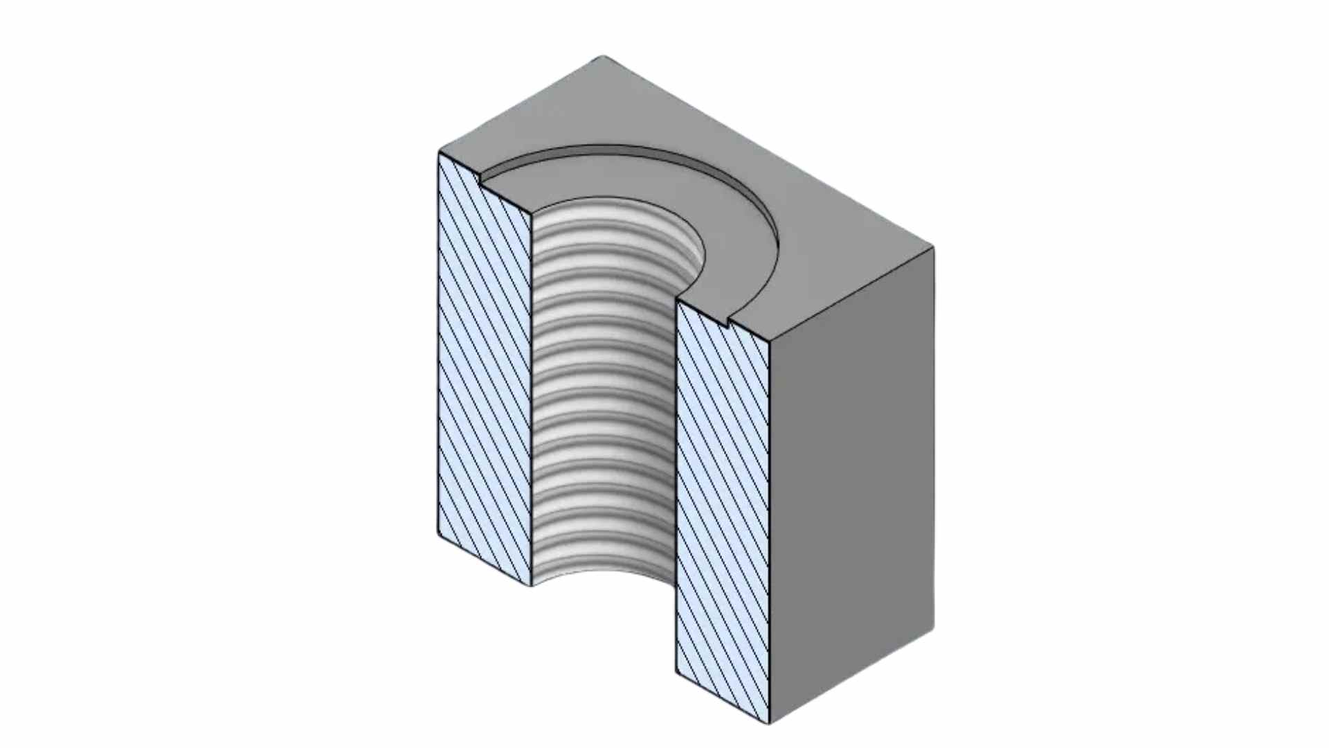
What Is a Spotface Hole?
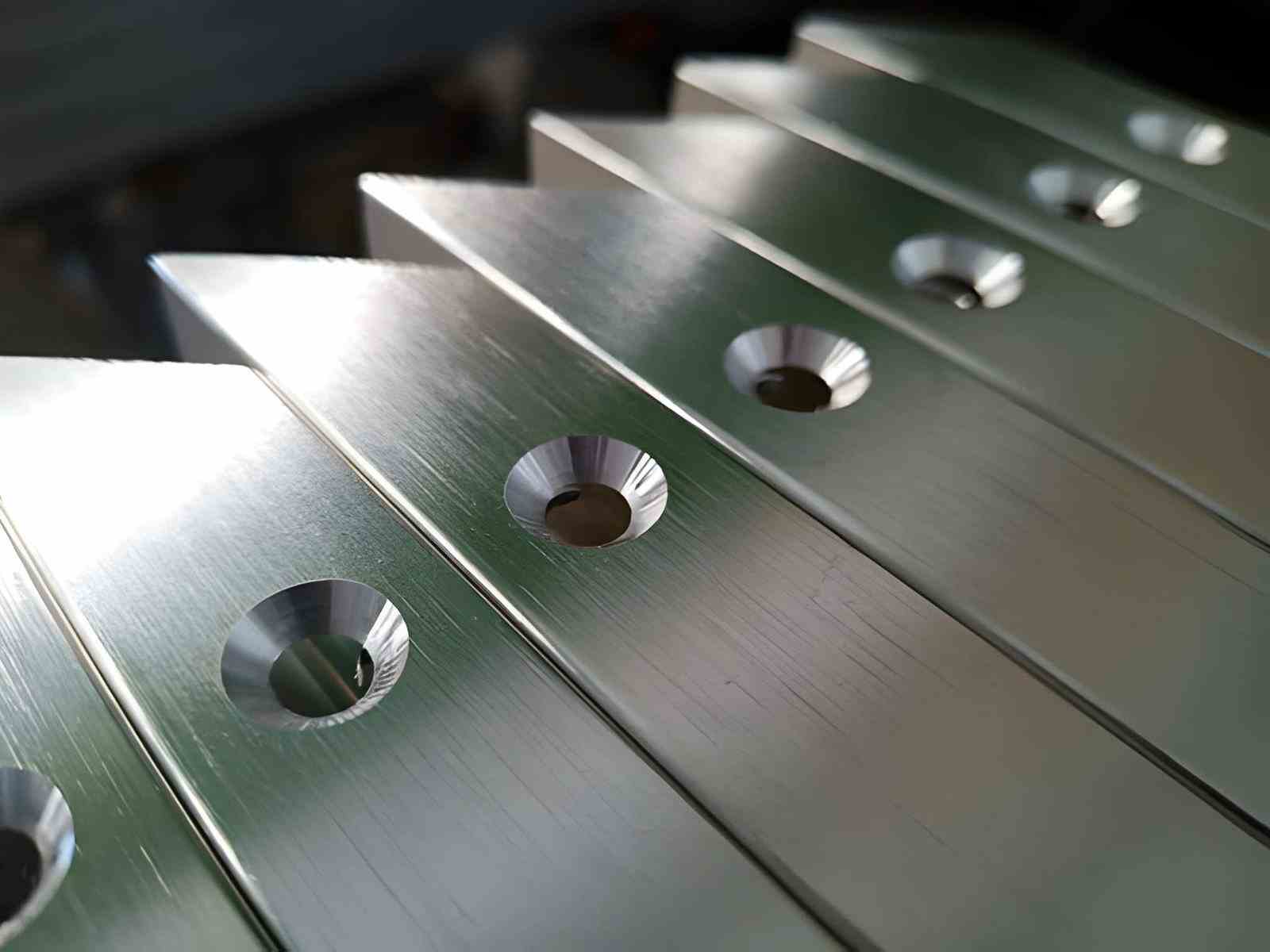
A spotface hole is a drilled hole with a shallow flat area machined around its opening.
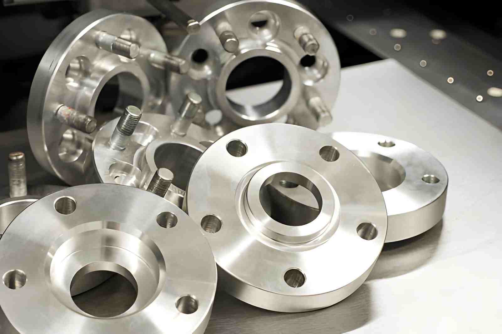
A CNC machine creates clean, flat spot faces on bolt holes of a wheel spacer mold. (Source: iStock)
Typical Geometry of a Spotface Hole
- A cylindrical drilled hole combined with a shallow flat recess around the entry.
- Spotface diameter sized to match the contact area of the fastener head or washer.
- Depth is limited to only correcting the seating surface.
- The flat surface is machined perpendicular to the hole axis to ensure proper load transfer.
Where Spotface Holes Appear in Mechanical Parts
- Cast housings where surface irregularities affect fastener seating.
- Mounting brackets and plates require localized flat contact areas.
- Forged components with draft angles and uneven surfaces.
- CNC-machined assemblies needing flat seating at bolt locations.
Spotface Callouts in Engineering Drawings
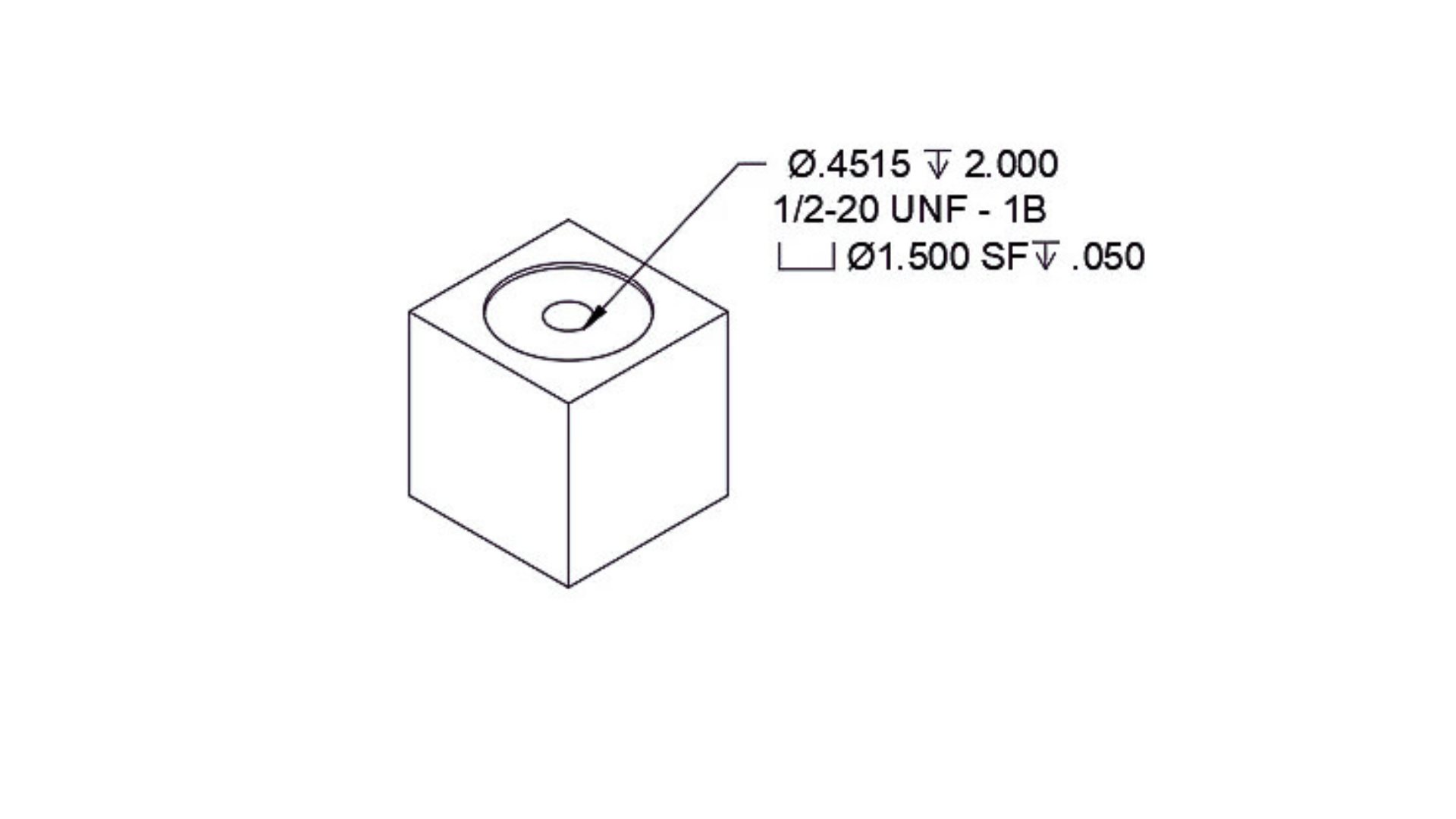
A simple illustration shows a spotface callout symbol with angle and diameter details. (Source:ampcnc)
- A spotface is defined using a standard symbol and a clear hole callout.
- Diameter and depth are specified alongside the hole dimension.
- Depth tolerance is applied when load control is required.
- Concentricity is maintained by aligning the tool with the hole center during machining.
Why Spotface Holes Are Used
Spotface holes are specified to create a controlled seating surface for fasteners. Based on our experience, they are most useful when the base surface alone cannot guarantee proper contact or load transfer.
A simple illustration shows a flat spot face around a hole for bolt seating. (Source: ampcnc)
Flat Seating Surfaces for Bolts and Washers
Spotfacing ensures that the fastener contacts a flat and stable surface. This helps maintain proper clamping force and alignment during tightening.
- Provides full contact under bolt heads or washers.
- Reduces point loading on uneven surfaces.
- Helps maintain consistent preload in bolted joints.
Assembly on Rough or Curved Surfaces
In castings, forgings, or rough machined parts, the surface around a hole is often not flat. Spotfacing corrects this locally without machining the full surface.
- Compensates for surface irregularities and draft angles.
- Improves assembly accuracy without full surfacing.
- Common in cast housings and structural components.
When a Full Counterbore Is Unnecessary
A spotface is used when only a small flat area is needed. It avoids unnecessary material removal and keeps machining efficient.
- Used when full recess depth is not required.
- Reduces machining time compared to counterboring.
- Maintains part strength by removing less material.
- Suitable for standard fastener seating without head clearance requirements.
Spot Face Machining: How Spotfacing Works in CNC Machining
Spotfacing is typically treated as a finishing step after drilling to clean the contact area before assembly.
Common Spotfacing Methods
- A spotface cutter is used in a single pass to clean the seating area.
- An end mill is used when the cutter size needs to match the fastener head or washer.
- Circular interpolation on CNC to control diameter and surface path.
- Face pass using shallow depth to avoid removing excess material.
Spotface Machining Sequence
- Drill hole to final diameter with required tolerance.
- Align the tool center with the hole using CNC coordinates or probing.
- Lower the tool to a shallow depth, just enough to clean the surface.
- Make a controlled circular pass to generate a flat seating area.
- Retract the tool and confirm surface contact for fastener seating.
Controlling Depth, Flatness, and Concentricity
- Depth set by Z-axis offset, verified with setup gauge or probe.
- Flatness depends on tool condition and machine rigidity during the cut.
- Concentricity comes from correct tool alignment with the hole center.
- In practice, we check the first part before running the batch to avoid deviation.
Spotface Cutters and Tooling Options
Spotfacing tools are selected based on hole size, material, and required surface quality. At JLCCNC, tool paths and cutter selection are optimized on CNC mills to maintain flatness, surface finish, and repeatability across batches.
What a Spotface Cutter Does
- Uses a guided pilot or stable geometry to stay aligned with the hole.
- Removes minimal material to avoid affecting the surrounding geometry.
- Maintains consistent flatness for fastener contact under load.
Common Spotfacing Tools
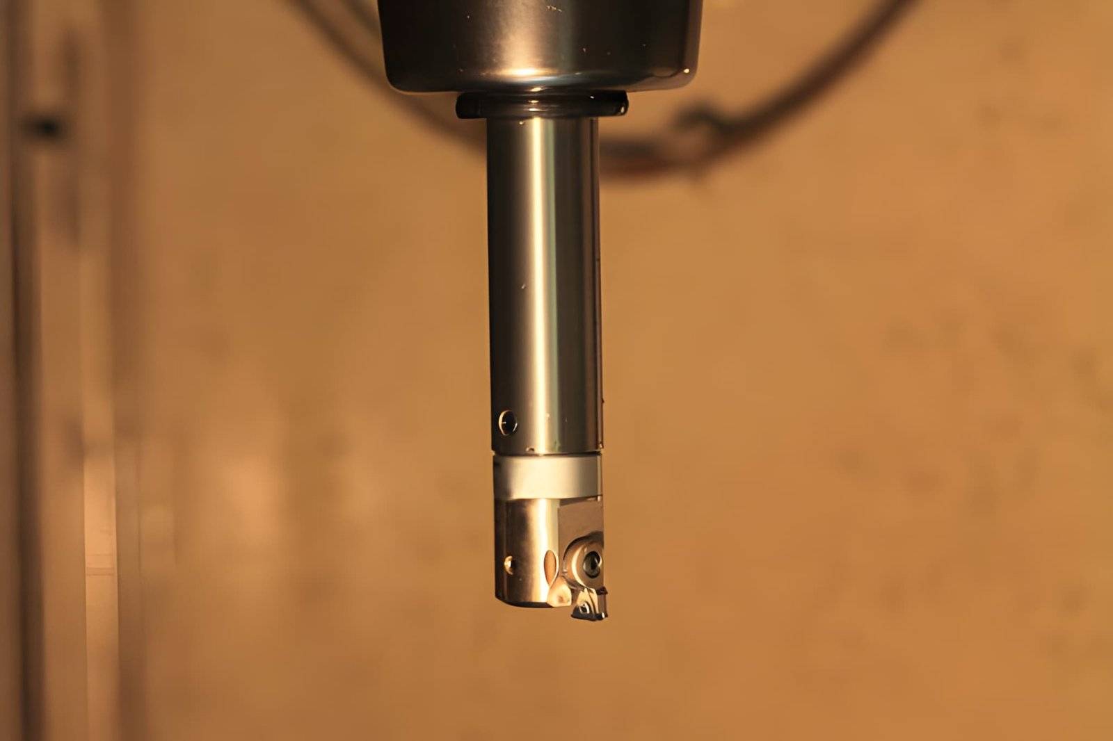
A close-up shows a back spotfacing cutter. (Source: iStock)
- Spotface cutters with a pilot for accurate hole alignment and stable cutting.
- End mills are used when flexibility in diameter or access is required.
- Counterbore tools for larger flat seating areas with controlled depth.
- Fly cutters are used for large-diameter spotfacing on flat surfaces.
Tool and Material Considerations for Spotfacing
Tool behavior shifts noticeably with material, even in a shallow operation like spotfacing. The cut itself is light, but surface finish and flatness depend on how the tool engages and wears over time.
- For aluminum, sharper tools with a higher rake angle tend to produce a cleaner edge. If the tool starts to dull, burrs appear quickly around the spotface perimeter, especially on softer grades.
- Stainless steel is less forgiving. Cutting forces increase, and edge wear becomes more visible across batches. Coated tools such as TiAlN are often used to maintain edge stability and reduce built-up edge during repeated passes.
- Carbon steel sits somewhere in between, but heat becomes the main variable. Coated tools help, though cutting parameters and chip evacuation often have just as much influence on the final surface.
Flute count also plays a role. Fewer flutes help with chip evacuation in softer materials, while harder materials benefit from higher flute counts to maintain cutting stability.
Tool wear directly affects consistency. A fresh cutter produces a flat, even seating surface. As wear progresses, the surface may still look acceptable, but contact quality starts to drift. In practice, early parts are usually checked, and tool changes are adjusted based on surface condition rather than fixed cycle counts.
Spotface vs Counterbore vs Countersink
A close-up of countersink milled holes in an aluminum facade profile. (Source: iStock)
All three features modify a hole, but they serve different functions in fastening and machining. In practice, the choice depends on the fastener type, required seating, and how much material needs to be removed.
Comparison Table
Feature | Spotface | Counterbore | Countersink |
|---|---|---|---|
Geometry | Shallow flat surface around a hole | Flat-bottomed recess with defined depth | Tapered conical recess |
Fastener Type | Bolt head, washer | Socket head cap screws | Flat head screws |
Material Removal | Minimal | Moderate to high | Minimal to moderate |
Primary Function | Creates flat seating on uneven surfaces | Fully recesses the fastener head below the surface | Allows flush or below-surface screw head |
Tooling | Spotface cutter, end mill | Counterbore tool, end mill | Countersink tool |
Typical Use Case | Cast or rough surfaces needing local flatness | Precision assemblies requiring flush fasteners | Applications needing a flush finish and minimal protrusion |
Design Guidelines for Spotface Features
Spotface features should match fastener size, surface condition, and machining limits. At JLCCNC, engineers review CAD files to ensure diameter, depth, and edge distance meet assembly requirements, allowing rapid adjustments if the initial setup requires fine-tuning.
Spotface Diameter Sizing
- Spotface diameter is often set around 1.5× to 2× the fastener head or washer diameter, depending on load and alignment requirements.
- Standard clearance adds 0.5 - 1.0 mm beyond the washer OD for alignment tolerance.
- Undersized spotfaces can cause partial contact and uneven load distribution.
Spotface Depth
- Typical depth ranges from 0.2 mm to 1.0 mm, depending on surface condition. (Read the guide on CNC boring machining)
- Cast or forged surfaces may need up to 1.5 mm to clean the seating area.
- Depth should only remove surface irregularities without weakening the section.
Edge Distance and Wall Thickness
- Maintain at least 1.5× fastener diameter from the hole center to the part edge.
- Wall thickness should be at least 2× the spotface depth to avoid deformation.
- Thin sections below 3 mm require careful evaluation before adding spotface features.
When Spotfacing Is Unnecessary
- Machined surfaces with flatness within 0.05 mm already provide proper seating.
- Through holes with washers may not require a spotface if contact is stable.
- Low-load fasteners where seating accuracy does not affect performance.
- Parts with tight tolerance surfaces that already control assembly alignment.
Common Spotfacing Problems and How to Avoid Them
Most problems come from over-specifying tolerances or poor layout. In our experience, small changes in dimensions fix most issues before machining starts.
Confusing Spotface and Counterbore
- Spotface depth: typically 0.2 to 1.0 mm, not a full recess.
- Counterbore depth: usually 3 to 10 mm for full head clearance.
- Using counterbore instead of spotface adds unnecessary machining time and tool wear.
Excessive Depth or Tolerance
- Keep depth around 0.5 mm for clean seating in most cases.
- Tolerance tighter than +/- 0.05 mm is rarely needed for spotface depth.
- Depth above 1.5 mm reduces section thickness around the hole.
Surface Condition and Load
- If surface flatness is within 0.05 mm, spotface may not be required.
- Rough cast surfaces often need 0.5 - 1.0 mm spotface depth.
- Poor seating causes uneven bolt load and early loosening.
Tool Access Issues
- Maintain at least 2 to 3 mm clearance from walls for cutter access.
- Small clearance forces use smaller tools and reduce rigidity.
- Restricted access leads to poor flatness and tool deflection during machining.
When to Use Spotfacing in Precision Parts
Spotfacing is used when the surface around a hole cannot support a fastener properly. It creates a small flat area so the bolt or washer seats correctly and loads evenly. We apply it only where it directly improves assembly performance.
Typical Applications
- Machined housings with uneven or cast surfaces around bolt holes.
- Mounting brackets where washers need full contact for stable tightening.
- Base plates where a consistent clamping force is required across multiple fasteners.
- Parts with mixed surfaces where only local flatness is needed.
Spotfacing in Prototypes and Low-Volume Production
- Used to fix surface variation without reworking the entire part.
- Helps confirm fit and fastening before production tooling is finalized.
- Useful when casting or forging surfaces are not fully controlled.
- Allows quick adjustment during early builds.
When Another Feature Is Better
- Counterbore when the bolt head must sit below the surface, typically 3 - 6 mm depth.
- Countersink when using flat head screws for flush installation.
- If surface flatness is already within 0.05 mm, spotface may not be needed.
- When no washer is used, the fastener sits directly on a machined face.
Spotfacing Services at JLCCNC
JLCCNC machines spotfaces to create a clean, flat seat around holes so fasteners sit properly. Work is done on CNC mills with controlled depth and alignment to the hole.
Spotface Machining and Tooling Options
- Spotfacing is done with end mills and spotface cutters on CNC mills.
- The tool path keeps the cutter centered on the drilled hole.
- Works with aluminum, stainless steel, and mild steel parts.
Fast Turnaround and Design Support
- Lead time usually is 1 to 3 days, depending on the part and quantity.
- Small changes in depth or diameter can be adjusted quickly.
- Works well for rapid prototypes and small batch parts.
Upload CAD files to JLCCNC and get spotface features machined with controlled depth and alignment, based on specific part requirements.
FAQ
Q: What Is a Spotface?
It’s the flat area machined around a hole so bolts and washers seat correctly. Engineers add it where the base surface is uneven or comes from casting.
Q: Is a spotface always shallower than a counterbore?
Yes. A spotface cleans the seating area, with a typical depth of 0.2–1.0 mm. A counterbore goes deeper, often 3 to 10 mm, since it’s used to fully recess a fastener head.
Q: Does a spotface require a depth callout?
Yes, without a defined depth, the machinist has no reference to control the cut. Most spotfaces are shallow, but the exact depth still needs to be specified on the drawing.
Q: Can a CNC machine make spotface holes in one setup?
Yes, in most cases, the hole is drilled first, and the spotface is added right after in the same setup. This keeps the spotface aligned with the hole and avoids re-clamping errors.
Q: What tool is used for spotfacing?
A spotface cutter with a pilot is common for standard sizes. An end mill is also used when the diameter needs to be flexible or when access is limited. Tool choice depends on hole size, material, and required finish.
Q: Can spotfaces be added to cast or forged parts?
Yes, spotfacing is often used on cast or forged parts where the surface is not flat. It creates a clean seating area so bolts and washers can sit properly and apply an even load during tightening.
Q: What are common mistakes when spotfacing holes in cast parts?
Typical errors include undercutting uneven surfaces, misaligning the cutter with the hole center, and over-specifying depth. These lead to poor seating or uneven bolt loads.
Q: How to choose the right cutter for spotfacing different materials?
Select a cutter based on material hardness and hole size. Sharp tools for aluminum, coated rigid tools for stainless steel, and heat-resistant tools for carbon steel. Adjust flutes and feed rates to maintain surface quality.
Q: Can spotfacing affect assembly tolerances?
Yes. If the spotface is too shallow, the bolt or washer may not sit fully flat, causing uneven load or misalignment. Excessive depth can weaken the surrounding material. Proper depth and flatness control are essential.
Popular Articles
• Cutting with Precision: A Comprehensive Guide to CNC Water Jet Technology
• CNC Coolant Explained: Types, Maintenance & Safety
• Rake Angle in Machining: Machinists’ Guide to Perfect Cuts
• What Steps Are Taken To Minimize Waste In CNC Machining Processes?
• How EDM Wire Cutting Works: Complete Guide to Precision CNC Wire Cutting
Keep Learning
Chatter in Machining: Causes, Effects, and How to Reduce It
CNC milling operation producing visible chatter marks on an aluminum workpiece Quick Chatter Diagnosis Checklist Symptom Most Likely Cause First Action High-pitched squeal Regenerative chatter Change spindle speed ±15% Chatter only in deep pockets Excessive tool overhang Shorten tool Chatter on thin walls Low workpiece rigidity Improve fixturing Chatter after tool replacement Runout / holder issue Check tool holder Chatter only during finishing DOC too small / rubbing Increase feed or adjust speed It ......
What Is Tool Offset in CNC? Types, Setup & Best Practices
CNC tool offset setup with measurement overlay Key Takeaways CNC offsets connect programmed intent with actual cutter position. Length data guides Z-axis depth control. Radius data protects part size during contour milling. Geometry values define the cutter's measured baseline. Wear values support fine correction during production. Verified data lowers scrap risk before full machining. Good offset habits protect tools, fixtures, and parts. In the context of CNC machining , tool offset is the quiet set......
Trochoidal Milling: Complete Guide to High-Efficiency CNC Machining
Key Takeaways Trochoidal milling combines circular cutter motion with continuous forward feed. The cutter normally engages 5 to 20% of its diameter instead of making a full-width cut. A smaller engagement angle limits force changes during slotting and pocket roughing. Low radial engagement often allows greater axial depths of cut than conventional slot milling. CAM software calculates the circular path automatically from the selected machining parameters. This strategy is widely applied to titanium, s......
What Is Die Casting? Process, Materials, and Applications
Key Takeaways Die casting is a metal casting process that forces molten metal into a reusable steel mold under high pressure, producing parts with tight tolerances and good surface finish at high volume. Aluminum die casting is the most common form by far, thanks to its combination of light weight, decent strength, and good corrosion resistance. The die casting process runs through mold preparation, injection, cooling, and ejection in a cycle that can repeat every few seconds to minutes depending on p......
First Angle vs Third Angle: Understanding Orthographic Projection Methods
Key Takeaways Orthographic projection is the system that lets a 3D part be represented through multiple 2D views, front, top, side, and so on. First angle projection and third angle projection are the two standard methods for arranging those views, and they place views in opposite positions relative to the object. First angle projection is the ISO standard used across most of Europe, India, China, Russia, and many other countries following ISO standards Third angle projection is the standard in the Un......
Micro EDM Machining: Capabilities, Materials, and Applications for Precision Components
Key Takeaways About Micro EDM Machining Only electrically conductive materials can be machined. Hole diameters can reach below 50 μm on specialized equipment. The process produces almost no mechanical cutting force, making it suitable for thin or delicate features. Surface integrity still requires attention because recast layers and heat-affected zones may remain after machining. Micro EDM is often combined with CNC machining, with milling producing the main geometry before EDM finishes critical micro......