Text Milling: CNC Lettering and Engraved Text Machining Explained
24 min
- What Is Text Milling?
- How CNC Text Milling Works: From CAD to Finished Engraving
- Design Rules for CNC Text
- Tooling and Cutting Strategy
- Text Engraving CNC Techniques and Methods
- CNC Engraved Text: Materials and Machining Considerations
- CNC Engraving vs Laser Marking vs Mechanical Etching
- CNC Lettering Applications in Manufacturing
- Custom CNC Engraved Text and Manufacturing Services
- Common Challenges in Text Milling
- FAQ About Text Milling and CNC Lettering
Key Takeaways
• Text milling is a CNC machining process that cuts lettering, numbers, and symbols directly into a part surface using programmed toolpaths.
• Text milling is used for part identification, regulatory markings, branding, and functional labeling across industries.
• Font selection, tool size, cut depth, and surface material all affect the final result.
• Engraved text produced by text milling is permanent, unlike labels or printing that degrades over time.
• CNC lettering requires specific consideration of minimum feature size relative to the tool diameter being used.
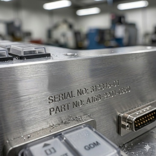
(AI generated) CNC machined aluminum panel with engraved industrial lettering
Text milling is a CNC machining process used to cut letters, numbers, and symbols directly into a part surface. Unlike printed labels or many surface-only marking methods, CNC text milling creates a permanent machined feature that resists wear, cleaning, and harsh service conditions. It is commonly used for serial numbers, part identification, control panels, industrial nameplates, and branded product surfaces. This guide explains how text milling works, how it compares with engraving and laser marking, and what design and tooling factors affect text quality.
You've seen CNC engraved text on machine nameplates, medical instruments, aerospace parts, and industrial panels. It looks simple. The process behind it isn't complicated either, but getting clean, consistent lettering on a CNC machine requires understanding a few things that most guides skip over.
This covers text milling from the ground up, how the process works, what affects quality, and how to specify it correctly the first time.
If your part requires permanent engraved text, JLCCNC can machine lettering, serial numbers, panel labels, and custom markings directly into the part during CNC production. This helps improve durability, alignment, and consistency while reducing the need for secondary marking processes.

Precision CNC Machining Service
Professional manufacturing, fast turnaround, and quality assurance.
What Is Text Milling?
Definition of Text Milling
Text milling is a CNC machining operation where a rotating cutting tool follows a programmed path to cut lettering, numbers, or symbols into a workpiece surface. The result is engraved text cut directly into the material rather than applied to the surface or printed on it.
That distinction matters more than it sounds. CNC engraved text doesn't peel, fade, or wear off. It survives the same conditions the part survives. On medical instruments that undergo repeated sterilization, engraved markings are generally more durable than printed labels and can remain legible throughout the service life of the part.
Text milling is a specialized form of CNC engraving focused on producing readable letters, numbers, and symbols rather than decorative patterns or general surface textures. It uses standard CNC milling equipment with toolpaths optimized for text geometry.
Common Uses of CNC Engraved Text in Manufacturing
Part identification is the most common application. Serial numbers, part numbers, date codes, and revision letters cut directly into machined components create a permanent record that stays with the part through its entire service life. In regulated industries, aerospace, medical, defense, this traceability is a compliance requirement, not optional.
Regulatory and safety markings on industrial equipment use text milling for the same permanence reason. Pressure ratings on fittings, voltage ratings on electrical housings, material callouts on chemical equipment, these markings need to survive the same environment the part operates in.
Tooling and fixture identification uses CNC lettering extensively. A fixture plate with twenty nearly identical locating positions needs clear, permanent text marking to prevent setup errors. Machined identification is one of the most durable marking methods for tooling that is exposed to coolant, chips, and repeated handling in production.
Medical instruments use CNC engraved text for size markings, product codes, and manufacturer identification that must remain readable after repeated sterilization cycles. Standard printing and labeling methods don't survive autoclaving. Text milling does.
Branding and cosmetic applications use CNC text milling on consumer products, custom parts, and presentation components where the engraved text is part of the product appearance. Anodized aluminum panels with CNC lettering, stainless steel nameplates, and machined trophy components all fall into this category.
How CNC Text Milling Works: From CAD to Finished Engraving
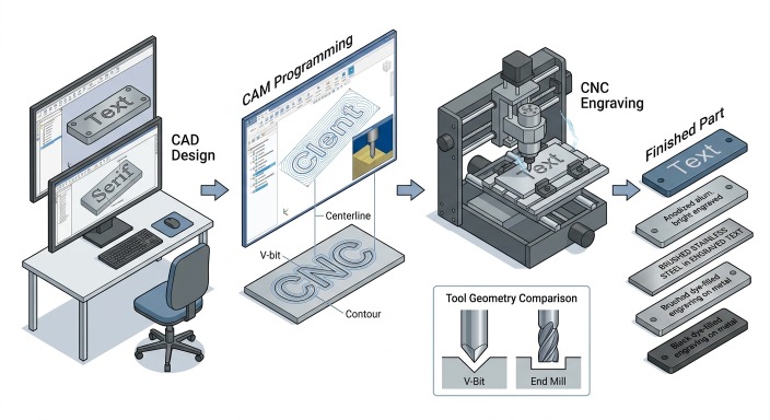
(AI generated) CAD to finished CNC text milling workflow
Text milling starts at the CAD stage, and decisions made there affect everything downstream. Font choice is the first one. Not every font that looks good on screen machines well. Serif fonts have small strokes at the ends of letters called serifs. At small character heights, those serifs are often thinner than the minimum tool diameter, which means they either do not get cut at all or come out distorted. Sans-serif fonts machine more cleanly because the stroke width is more uniform throughout each character.
Letter spacing matters too. CNC lettering that is too tightly spaced leaves thin walls of material between adjacent characters. At greater depths, those thin walls can chip or deflect during machining. Most CAM software lets you adjust character spacing, and opening it up slightly relative to the default improves both machining quality and readability on finished parts.
Text orientation on the part affects tool access and fixturing. CNC engraved text on a flat surface is straightforward. Text on an angled face, a curved surface, or a recessed panel requires either a 4/5-axis setup or careful fixturing to keep the tool perpendicular to the machining surface. If the tool is not properly aligned with the surface, the engraved text can show inconsistent depth and uneven line width.
Toolpath Generation
The starting point is a CAM program that converts text into toolpaths. Most CAM software has built-in text milling functions: you select a font, type the text, set the character height, and the software generates the toolpaths that cut each letter. Tool diameter is the first constraint. The smallest internal radius in any letter cannot be smaller than the tool radius. If the selected tool is too large to fit inside those curves, the letters come out with missing material or distorted geometry where the tool cFor small text milling work, character heights below 5 mm often force the use of small-diameter tools, typically 0.5-2 mm end mills or engraving tools, which introduce their own challenges around rigidity and feed rate. Depth of cut in CNC text milling is typically 0.1-0.5 mm for standard identification marking, and deeper for decorative or high-visibility applications. Deeper cuts produce more visible text but increase machining time and require stiffer tooling to avoid deflection.
Centerline vs Contour Engraving
The cutting action in text milling is either single-line engraving or pocket milling of each letter. CAM software generates text milling toolpaths in two common ways. Centerline engraving follows a single path down the middle of each character stroke. This is faster and works well for most identification marking. Contour engraving offsets the toolpath to the outside or inside of the character outline and cuts the full letter profile. It is slower but produces sharper, more defined characters that read cleanly at larger sizes.
For CNC text milling at character heights below 4 mm, centerline engraving with a V-bit is almost always the right approach. The V-bit geometry self-adjusts depth to maintain consistent cut width as it follows curves and corners, which a flat end mill cannot do on fine text. Above 4-5 mm character height, contour toolpaths with an end mill or ball nose produce better results because the letter geometry is large enough for the tool to define properly.
Pocket milled letters cut out the full character profile to a consistent depth. This takes longer but produces cleaner, more legible results at larger character sizes.
Feed / Speed / CAM Considerations
Post-processor settings affect text milling quality more than most programmers expect. Feed rate needs to be lower than bulk milling. Fine text engraving on aluminum typically runs 500-1500 mm/min compared to 2000-5000 mm/min for standard milling. Spindle speed runs high, 15,000-24,000 RPM for small engraving tools, to maintain adequate surface speed at small diameters.
Fine text milling puts disproportionate demands on cutting tools compared to bulk material removal. Small engraving tools complete thousands of short direction changes per character, and micro-chipping on the cutting edge shows up as ragged edges on fine CNC lettering. Chip evacuation in text milling grooves is also worse than in open pockets because the groove is narrow and the tool revisits the same confined space on every pass. Chips that do not clear the groove get recut, which damages surface finish and accelerates tool wear.
Air blast directed at the cutting zone is often more effective than flood coolant for fine text milling. On deep engraving passes, pecking cycles help by clearing chips from the groove between depth steps. The cycle takes longer but produces cleaner groove walls and extends tool life on fine text work.
Surface Finish and Visibility
The relationship between surface finish and text readability depends on the application. What matters most is the contrast between the engraved area and the surrounding surface. For identification marking that gets read under normal lighting, the machined surface inside the engraved grooves does not need to be particularly smooth. Anodized aluminum is the clearest example. Machining engraved text into a pre-anodized surface removes the anodize layer inside the grooves, exposing bare aluminum and creating highly readable text without any secondary treatment.
On stainless steel, the natural contrast between engraved and unengraved surface is low. Ink filling after text milling, laser blackening of the engraved area, or specifying the background surface as brushed while the engraved text is polished creates the contrast that makes CNC engraved text readable.
Design Rules for CNC Text
Text milling quality depends heavily on text geometry. A readable font on a screen does not automatically machine well on metal or plastic. The main design factors are font style, stroke width, letter spacing, character height, engraving depth, and the smallest internal features that the cutting tool must reproduce.
Sans-serif fonts are usually the best choice for CNC lettering because their stroke widths are more uniform and their geometry is easier to machine. Serif fonts can work at larger sizes, but the small terminal features often become difficult to reproduce cleanly when the text is reduced. Decorative or script fonts are the least reliable because they often contain sharp internal corners, thin connecting strokes, and tight curves that exceed practical tool limits.
Minimum text size is controlled by both the font geometry and the smallest usable cutting tool. In aluminum, simple sans-serif text can often be engraved at character heights around 2 mm with fine tooling, but production-safe design usually starts higher than that. Across common engineering metals, a minimum character height of about 4 mm is a practical conservative rule for consistent CNC text milling without relying on specialized micro-engraving tools. Harder materials such as stainless steel and titanium generally require larger text for stable results.
Letter spacing is also important. When characters are placed too closely together, the remaining material between letters becomes thin and fragile, especially at greater engraving depths. Slightly increasing the spacing beyond the font default often improves both machinability and readability.
Depth should be selected based on visibility and function rather than aesthetics alone. Shallow engraving in the 0.1-0.2 mm range is fast and suitable for light marking, but it may be difficult to read in poor lighting or after surface wear. Depths around 0.3-0.5 mm typically provide a good balance between readability, machining time, and low impact on part strength. Deeper engraving may be needed for harsh-service applications, but it increases cycle time and can create stress concentration concerns in load-bearing areas.
Tool radius is one of the most important limitations in text milling. Internal corners and tight curves cannot be cut sharper than the effective cutting radius of the tool. If the font contains details smaller than the cutter can reach, corners become rounded, enclosed areas close up, and letterforms lose clarity. This is why small text usually requires V-bits or very small engraving tools, while larger text can be machined more predictably with end mills.
Readable text also depends on contrast. Even perfectly machined lettering can be hard to see if the surrounding surface and the groove reflect light in the same way. Surface finish, anodizing, ink fill, and background texture all influence visibility, sometimes more than the engraving depth itself.
How to Specify CNC Engraved Text on a Drawing
If engraved text is important to function, traceability, or appearance, it should be defined clearly on the engineering drawing rather than left to shop interpretation. A vague note such as “engrave text” is often not enough to control readability, size, placement, or finished appearance.
A complete drawing callout should define the text content, character height, depth, and location on the part. If a specific font is required for branding or consistency, the font family or an equivalent style should also be stated. Where readability matters, the drawing should indicate whether the text is centerline engraved, contour engraved, or pocket milled, since each method produces a different visual result.
The surrounding surface condition may also need to be specified. For example, anodized aluminum panels may rely on exposed base metal for contrast, while stainless steel text may require ink fill, a brushed background, or another secondary treatment to remain legible. If contrast is critical, that requirement should appear in the drawing or part specification instead of being assumed.
Text location usually does not require tight dimensional tolerances unless it must align with holes, controls, labels, or mating features. In those cases, the drawing should reference datums or clearly dimension the text relative to functional geometry. If orientation matters, such as on angled faces or control panels, that should also be shown explicitly.
For production parts, it is also good practice to define the minimum acceptable readability rather than only the nominal geometry. This is especially useful for serial numbers, regulatory markings, or small identification text where tool size, material, and finish may affect the final appearance.
A practical drawing note for CNC engraved text may include the following items:
text content
font or style requirement
character height
engraving depth
engraving method if important
location and orientation
finish or contrast requirement
fill requirement if applicable
tolerance only where functionally necessary
Tooling and Cutting Strategy
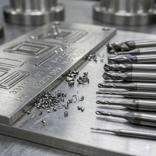
(AI generated) V-bits and micro end mills used for CNC text milling and engraving
Tool selection has a major effect on text quality, cycle time, and process reliability. In most CNC text milling work, the main choice is between a V-bit, a small end mill, or a ball nose cutter.
V-bits are commonly used for fine lettering and shallow engraved text because their pointed geometry can create sharp visual definition in small characters. They are especially effective for centerline engraving, where the cutter follows the middle of each stroke. At small character sizes, V-bits usually produce cleaner-looking text than flat end mills because they can reach narrow internal features with a much smaller effective cutting width.
End mills are better suited to contour engraving, pocketed letters, and applications that require a more consistent groove width or a flat-bottomed profile. They are often preferred for larger text, filled engravings, and recessed lettering where geometric consistency matters more than a sharp tapered appearance. Ball nose tools can also be useful when a rounded groove profile is preferred.
As a practical rule, V-bits are generally the better choice for text below about 4-5 mm character height, while end mills become more effective as the text gets larger and the geometry opens up. The exact crossover depends on the font, material, and required groove shape.
Micro tools require careful process control. Small-diameter cutters are sensitive to spindle runout, tool deflection, and chip recutting. A tool that still appears usable in general milling may already be too worn for fine lettering, where even small edge damage shows up as ragged corners or widened strokes.
Cutting parameters should be lighter and more stable than in standard milling. Fine text machining usually benefits from high spindle speed, controlled feed, shallow passes, and reliable chip evacuation. Air blast is often more effective than flood coolant in narrow engraving grooves because it clears chips without trapping them in confined features. On deeper engraving work, multiple depth passes with retraction can improve groove cleanliness and reduce tool stress.
Tool diameter should always be selected against the smallest internal feature in the text. If the cutter is too large for the font geometry, no amount of machine accuracy will restore the intended letter shape. For that reason, text should be reviewed as a manufacturable feature rather than treated like ordinary 2D graphics.
Text Engraving CNC Techniques and Methods
| Technique | How It Works | Depth Range | Best For | Limitations |
|---|---|---|---|---|
| V-bit engraving | Conical tip follows centerline path, cut width increases with depth | 0.1–0.8mm | Fine CNC lettering below 5mm height, general identification marking, anodized aluminum | Variable line width, V-groove profile not suitable for ink fill requiring flat bottom |
| Single-pass end mill | Flat or ball nose end mill follows character outline at fixed depth | 0.2–2.0mm | Larger CNC engraved text above 5mm height, consistent groove width for ink filling | Internal corner radius limited by tool diameter, can't match V-bit on fine text |
| Pocket milled letters | End mill clears full character area to uniform depth | 0.3–3.0mm | High-visibility raised or recessed text, branding, logo engraving | Slow, higher tool wear, requires larger character sizes for clean results |
| Surface engraving | Very shallow pass, 0.05–0.15mm depth | 0.05–0.15mm | Soft materials, cosmetic marking on finished surfaces | Low durability, poor readability in harsh environments, not suitable for hard metals |
| Deep engraving | Multiple depth passes to achieve significant groove depth | 0.5–5.0mm | Part identification on rough-handled components, permanent marking on structural parts | Stress concentration risk on load-bearing sections, significantly longer cycle time |
| Helical ramp entry | Tool enters groove on a spiral path rather than direct plunge | Varies | Hard materials where direct plunge causes tool deflection or chipping | Requires more programmed moves, marginal benefit on soft materials |
| Contour engraving | Toolpath offset to character edge, cuts profile rather than centerline | 0.2–1.5mm | Clean character definition at medium to large sizes, precise cnc text milling on presentation parts | Requires font geometry larger than tool diameter throughout, slow on complex fonts |
CNC Engraved Text: Materials and Machining Considerations
Aluminum Text Engraving
Aluminum is one of the easiest and most common materials for CNC text milling. It machines cleanly at high spindle speeds, supports fine detail, and generally allows smaller character sizes than harder metals. Grades such as 6061-T6 are widely used for engraved panels, housings, and industrial nameplates.
One of aluminum’s biggest advantages is contrast. When text is engraved into a pre-anodized surface, the cut exposes bright bare aluminum beneath the colored coating, creating highly legible lettering without additional processing. This is one reason anodized aluminum is widely used for control panels, instrument plates, and branded equipment components.
The main machining concern in aluminum is burr formation along the groove edges, especially with small tools or aggressive parameters. Sharp cutters, stable feeds, and light deburring usually solve the problem. Cast aluminum can produce rougher edges than wrought grades because of silicon content and porosity, so appearance-critical text is often better machined on wrought stock.
Stainless Steel Engraving Challenges
Stainless steel provides durable and permanent engraved text, but it is less forgiving than aluminum. Work hardening, higher cutting forces, and lower natural contrast all make text milling more demanding.
Tooling, feed, and chip evacuation need tighter control in stainless steel to avoid rough groove walls and poor edge definition. Small text is possible, but production consistency usually improves when the character height is increased and engraving geometry is simplified.
Readability is often the bigger issue. Engraved stainless steel may have limited visual contrast unless the design includes ink fill, selective surface finishing, or different background texture. For this reason, text on stainless parts should be designed with visibility in mind rather than relying on depth alone.
Plastic and Acrylic CNC Lettering
Many plastics machine well for CNC lettering, especially acrylic, POM, and nylon. These materials can produce clean text and support small character sizes, but heat control becomes more important than it is in metal cutting.
Acrylic requires sharp tools and appropriate feed rates to avoid melting or smearing. When machined correctly, the groove often appears frosted against a polished background, which improves visual contrast. This makes acrylic a common choice for signs, cosmetic covers, and display panels.
Engineering plastics such as POM and nylon also machine cleanly and are practical for fixtures, housings, and industrial components with engraved labeling. Very soft materials such as PTFE or elastomeric plastics are poor candidates because they deform under the tool instead of holding crisp text geometry.
CNC Engraving vs Laser Marking vs Mechanical Etching
| Factor | CNC Text Milling | Laser Marking | Chemical Etching |
|---|---|---|---|
| Depth | 0.05–5.0mm, controllable | Surface only, 0.001–0.1mm typical | 0.01–0.5mm depending on process time |
| Material removal | Yes, cuts material | Vaporizes surface layer or changes color | Dissolves material chemically |
| Durability | Excellent, permanent groove in material | Good on most metals, can fade on soft surfaces | Good, but etch depth limits longevity on wear surfaces |
| Speed | Slow on complex text, fast on simple marking | Very fast, seconds per part | Slow setup, fast batch processing |
| Setup cost | Low, standard CNC equipment | High, dedicated laser system $15,000-150,000+ | Low equipment cost, chemical handling overhead |
| Per part cost | Low at low volume | Low at high volume | Very low at high volume |
| Minimum feature size | 0.3-0.5mm limited by tool | 0.05-0.1mm, finer than CNC | 0.1-0.2mm |
| Materials | Most metals and plastics | Metals, some plastics, anodized aluminum | Metals only, material-specific chemistry |
| Depth control | Precise, programmed | Limited, not a deep engraving process | Inconsistent, time and chemistry dependent |
| Surface distortion | None beyond cut groove | Potential heat affected zone on thin parts | Potential undercutting on fine features |
| Readability on metals | Good with contrast treatment | Excellent on stainless, good on aluminum | Good on aluminum, variable on steel |
| Regulatory acceptance | Widely accepted for part marking | Accepted in most industries | Accepted, but chemical traceability required |
| Best application | Production CNC engraved text on machined parts | High-speed marking on finished parts | Batch marking of flat sheet components |
| Worst application | High volume identical parts needing marking only | Deep permanent engraving on rough-handled parts | Curved surfaces, complex 3D geometry |
Which to choose: CNC text milling is usually the best choice when the text is added during the same machining setup as the part, when physical engraving depth matters, or when a permanent machined feature is preferred over a surface mark. Laser marking is often faster for high-volume identification on finished parts with good access. Chemical etching is more suitable for flat sheet components and batch processing where shallow marking is acceptable.
CNC Lettering Applications in Manufacturing
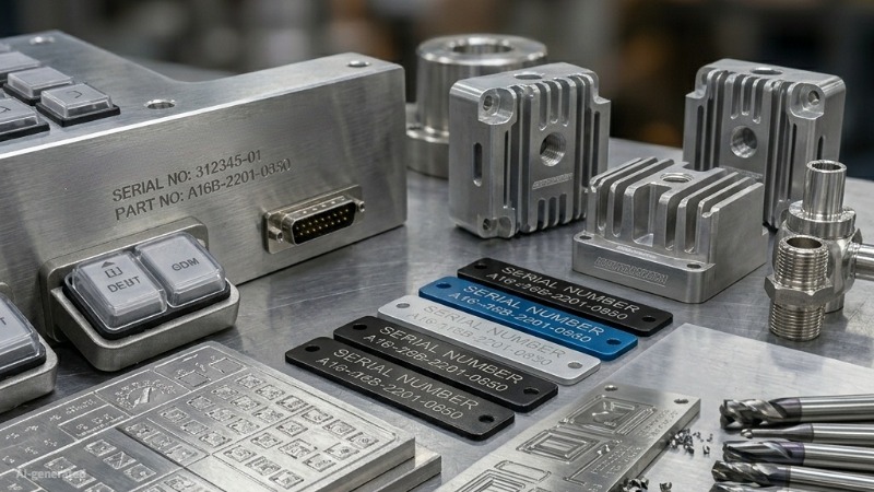
(AI generated) industrial CNC engraved materials
Product Identification and Serial Numbers
Permanent part identification is one of the most common uses of text milling. Part numbers, serial numbers, date codes, lot codes, and revision markings can be machined directly into the component so the information remains with the part throughout its service life. This is especially valuable in industries where traceability, inspection, or long-term durability are important.
Branding and Logo Engraving
Text milling is also used for product branding, company names, model names, and logos on machined components. Compared with printed labels, machined branding is more durable and can better match the appearance of premium metal products. Branding applications usually require closer attention to font consistency, spacing, and small geometric details than simple identification marks.
Control Panels and Nameplates
Control panels and nameplates often combine dense layouts of labels, symbols, and hardware cutouts on the same part. CNC text milling works well here because the lettering can be machined in the same setup as holes, slots, and mounting features, improving positional consistency. Anodized aluminum is especially common for these parts because it combines easy machining with strong visual contrast after engraving.
Custom CNC Engraved Text and Manufacturing Services
Custom text milling makes sense when engraved text is part of the component itself rather than an added label or secondary mark. This is common for control panels, nameplates, part identification features, branded housings, fixture labels, and machined components that need permanent, wear-resistant text. It is also a practical choice when the text must align closely with holes, cutouts, datums, or other machined features on the same part.
For quoting and production, the typical files needed are a 2D drawing, a 3D CAD model if the part geometry is more complex, and a clear note defining the text content, character height, depth, location, and any finish or contrast requirement. If a specific font, logo, or layout matters, that information should be included in the drawing package rather than left to interpretation.
Prototype and production text milling often use the same core process, but the priorities are different. Prototype work usually focuses on verifying readability, size, placement, and appearance on the actual material and finish. Production work places more emphasis on repeatability, tool life, cycle time, and maintaining consistent text quality across larger quantities.
One of the main advantages of CNC engraved text is that it can be machined in the same setup as the rest of the part. When text, holes, pockets, and outer profiles are cut in one operation, the engraved features stay accurately aligned to the part geometry without requiring a second fixture or secondary marking step. This same-setup approach reduces handling, lowers the risk of positional error, and improves consistency from part to part.
Engraving during machining also improves accuracy because the text location is referenced directly from the same machine coordinate system used for the functional features. That matters on panels, instrument faces, fixture plates, and identification surfaces where text must line up visually or dimensionally with adjacent features. Instead of adding markings later and trying to register them to the finished part, the engraving is built directly into the machining process.
If custom engraved text is required on a machined part, it is usually best to define it early in the design and quoting stage. Clear drawings, realistic text geometry, and matched tooling strategy help avoid small-feature problems later in production. JLCCNC can support custom CNC engraved text as part of the overall machining process, from prototype parts to repeat production, especially where text accuracy, permanence, and alignment with machined features are important.
Precision CNC Machining Service
Professional manufacturing, fast turnaround, and quality assurance.
Common Challenges in Text Milling
The most common text milling problems are poor edge definition, burr formation, inconsistent depth, and low readability. These issues usually come from one of four causes: the font is too fine for the selected cutter, the tool is worn or too large for the geometry, chips are not clearing from narrow grooves, or the finished surface does not provide enough visual contrast.
Most of these problems can be prevented early in the design stage. Simple fonts, adequate character spacing, realistic minimum text size, stable cutting parameters, and attention to contrast usually matter more than pushing for the smallest possible lettering.
FAQ About Text Milling and CNC Lettering
Q: What is text milling in CNC machining?
Text milling is the process of machining letters, numbers, logos, or markings into a material using CNC cutting tools.
Q: What tools are used for CNC lettering?
V-bits, engraving cutters, and small end mills are the most common tools used for CNC lettering and text milling.
Q: Can CNC machines engrave stainless steel text?
Yes, CNC machines can engrave stainless steel text using carbide engraving tools, proper feeds and speeds, and rigid machine setups.
Q: What is the difference between engraving and text milling?
Engraving usually creates shallow surface markings, while text milling often involves deeper machined lettering with defined pocket geometry.
Q: What is the minimum text size for CNC engraving?
Minimum text size depends on the material, font, and tool geometry. As a general guideline, about 4 mm character height is a conservative choice for reliable machining across common metals.
Popular Articles
• Cutting with Precision: A Comprehensive Guide to CNC Water Jet Technology
• CNC Coolant Explained: Types, Maintenance & Safety
• Rake Angle in Machining: Machinists’ Guide to Perfect Cuts
• What Steps Are Taken To Minimize Waste In CNC Machining Processes?
• How EDM Wire Cutting Works: Complete Guide to Precision CNC Wire Cutting
Keep Learning
Trochoidal Milling: Complete Guide to High-Efficiency CNC Machining
Key Takeaways Trochoidal milling combines circular cutter motion with continuous forward feed. The cutter normally engages 5 to 20% of its diameter instead of making a full-width cut. A smaller engagement angle limits force changes during slotting and pocket roughing. Low radial engagement often allows greater axial depths of cut than conventional slot milling. CAM software calculates the circular path automatically from the selected machining parameters. This strategy is widely applied to titanium, s......
What Is Die Casting? Process, Materials, and Applications
Key Takeaways Die casting is a metal casting process that forces molten metal into a reusable steel mold under high pressure, producing parts with tight tolerances and good surface finish at high volume. Aluminum die casting is the most common form by far, thanks to its combination of light weight, decent strength, and good corrosion resistance. The die casting process runs through mold preparation, injection, cooling, and ejection in a cycle that can repeat every few seconds to minutes depending on p......
First Angle vs Third Angle: Understanding Orthographic Projection Methods
Key Takeaways Orthographic projection is the system that lets a 3D part be represented through multiple 2D views, front, top, side, and so on. First angle projection and third angle projection are the two standard methods for arranging those views, and they place views in opposite positions relative to the object. First angle projection is the ISO standard used across most of Europe, India, China, Russia, and many other countries following ISO standards Third angle projection is the standard in the Un......
Micro EDM Machining: Capabilities, Materials, and Applications for Precision Components
Key Takeaways About Micro EDM Machining Only electrically conductive materials can be machined. Hole diameters can reach below 50 μm on specialized equipment. The process produces almost no mechanical cutting force, making it suitable for thin or delicate features. Surface integrity still requires attention because recast layers and heat-affected zones may remain after machining. Micro EDM is often combined with CNC machining, with milling producing the main geometry before EDM finishes critical micro......
Bearings: Types, Applications, Materials, and Selection Guide
Bearings are small components, but they play a critical role in the reliability of mechanical systems. The wrong bearing selection can lead to excessive friction, vibration, premature wear, and unexpected equipment downtime. In this guide, I'll break down every common type of bearing, what they're used for, and how to choose the right one for your project. Whether you're a mechanical engineer, a hobbyist, or just someone trying to understand how things work, this guide has you covered. What Are Bearin......
CNC Cutting Fluid: Types, Functions, Applications, and Selection Guide
Key Takeaways Cutting fluid in machining performs four functions simultaneously: cooling the tool and workpiece, lubricating the tool-chip interface to reduce friction, carrying chips away from the cut zone, and protecting machined surfaces from corrosion between operations. Different machining operations need different fluid priorities: high-speed aluminum milling may need adhesion control and chip evacuation, threading and tapping need strong lubrication, and grinding requires both cooling and fine ......