Straightness GD&T Symbols and Tolerance Guide for Precision Manufacturing
22 min
- What Is Straightness GD&T?
- How to Read a Straightness Callout
- How Straightness Tolerance Zones Work
- Surface Straightness GD&T Explained
- Axis Straightness GD&T for Cylindrical Features
- Selecting Straightness Tolerances in Engineering Drawings
- What Causes Straightness Errors in Manufacturing
- Residual Stress and Material Movement
- GD&T Straightness Examples and Drawing Interpretation
- Measuring and Inspecting Straightness
- Straightness GD&T vs Other Geometric Tolerances
- Best Practices for Controlling Straightness
- FAQs About Straightness GD&T
Key Takeaways
- Straightness GD&T is a form control that limits how much a line element or axis can deviate from a perfectly straight line.
- It appears as a horizontal line symbol in a feature control frame with no datum reference, straightness never references a datum because it controls the feature relative to itself, not relative to anything else.
- Surface straightness controls individual line elements on a surface.
- Axis straightness controls the derived axis of a cylindrical feature and can be applied with maximum material condition (MMC) to allow bonus tolerance.
- Straightness tolerance zones are either two parallel lines (surface) or a cylinder (axis), and the controlled element must lie entirely within that zone.
- Straightness errors in manufacturing come from tool deflection, thermal distortion, residual stress release, and fixturing instability, all of which can produce a dimensionally correct part that fails the straightness requirement.
(GD&T basics) straightness illustration
A shaft can measure the correct diameter at every cross-section and still fail in assembly if it bows along its length. A machined face can pass a thickness check and still rock on a surface plate.
Dimensional tolerances control size, but they do not control form. That is the purpose of straightness in GD&T. The distinction between surface straightness and axis straightness is also where many engineers new to GD&T get confused.
This guide covers both types and focuses on interpretation logic rather than the brief definition-only treatment found in many GD&T references.
What Is Straightness GD&T?
Straightness GD&T is a form tolerance that controls how much a surface element or feature axis may deviate from a theoretically perfect straight line without reference to a datum.
Definition of Straightness GD&T
Straightness in GD&T is a form control that limits how much a line element or axis can deviate from a perfectly straight line. It appears as a horizontal line symbol in a feature control frame and never uses a datum reference, because it controls the feature relative to itself rather than to another feature.
Purpose of Straightness Tolerance
Size tolerances control how large or small a feature is. They don't control its shape between measurement points. A shaft with a diameter tolerance of 25.00 ± 0.05 mm can be within size limits at every cross-section and still have a noticeable bow along its length. The diameter is acceptable, but the axis is not straight. Straightness GD&T catches that bow. It's not a replacement for the size tolerance, it works alongside it.
Why Straightness Is Important in Manufacturing
Straightness matters for two main reasons: function and assembly. Functionally, a bowed shaft running in bearings induces cyclic bending stress at the bearing locations that reduces fatigue life and increases bearing load. The shaft meets dimensional spec. It still fails prematurely. Straightness GD&T on the axis prevents this by limiting how much the shaft can deviate from a straight line between bearing journals.
For assembly, a cylindrical feature that needs to pass through a hole in the mating component has a length-dependent assembly requirement that diameter tolerance alone doesn't control. A shaft that's 0.02mm under the maximum diameter at every cross-section but bows 0.15mm over its length may not pass through a close-fitting bore, even though every individual diameter measurement is within spec. Axis straightness GD&T closes this gap.
For straightness-critical parts such as shafts, guide rails, and precision mating features, manufacturing capability matters as much as drawing interpretation. JLCCNC supports CNC machining for custom parts that require controlled form accuracy, stable process planning, and inspection methods matched to the tolerance requirement, helping engineers move from GD&T callouts to manufacturable parts with reliable results.

Precision CNC Machining Service
Professional manufacturing, fast turnaround, and quality assurance.
How to Read a Straightness Callout

(GD&T basics) straighntess symbol
The straightness symbol in GD&T is a single horizontal line shown in the feature control frame. It is always used without a datum reference because straightness is a form control.
To interpret the callout correctly, first determine what the frame is attached to. If it points to a surface, it controls surface straightness. If it is associated with the diameter dimension of a cylindrical feature, it controls axis straightness.
The tolerance zone depends on the type of straightness being specified. Surface straightness uses two parallel lines or planes separated by the tolerance value. Axis straightness uses a cylindrical tolerance zone whose diameter equals the stated tolerance value. When the diameter symbol appears before the tolerance value, it indicates a cylindrical zone for the derived median line.
A correct interpretation also requires checking whether a material condition modifier is present. Surface straightness does not use MMC or LMC. Axis straightness may use a material condition modifier when applied to a feature of size, which can allow bonus tolerance as the actual size departs from MMC.
How Straightness Tolerance Zones Work
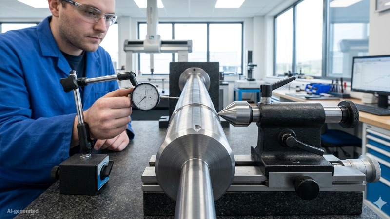
(AI generated) Shaft setup showing straightness tolerance zone
Straightness as a Form Control
Form controls in GD&T, straightness, flatness, circularity, cylindricity, share a defining characteristic: they control the shape of a feature without reference to any external datum. The tolerance zone is derived from the feature being controlled, which is why no datum reference is appropriate or permitted.
This makes straightness GD&T independent of location and orientation. A shaft that's positioned incorrectly in an assembly still has its straightness evaluated independently, the axis is extracted from the feature geometry, and the measured median line is evaluated against the applicable straightness tolerance zone. In practice, inspection software may use a defined fitting method to report the deviation. Where the shaft is located in space is irrelevant to the straightness evaluation.
Surface vs Axis Tolerance Behavior
| Factor | Surface Straightness | Axis Straightness |
|---|---|---|
| What is controlled | Individual line elements on surface | Derived median line of cylindrical feature |
| Tolerance zone shape | Two parallel planes (2D per line element) | Cylinder (3D) |
| Tolerance value represents | Width between two parallel planes | Diameter of cylindrical zone |
| Datum reference required | No | No |
| MMC/LMC modifier applicable | No | Yes |
| Verification method | Dial indicator scan along surface | CMM median line extraction or functional gauge |
| Typical application | Flat surfaces, sliding faces, sealing surfaces | Shafts, pins, cylindrical features in assembly |
| Relationship to size tolerance | Independent, both must be met | Can exceed size tolerance when MMC applied |
| Rule #1 applicability | Not usually specified through Rule #1 alone | Axis straightness overrides Rule #1 |
Straightness Without Datum Reference
The absence of a datum reference in a straightness callout is not an omission; it is a defining characteristic of the control. Every other orientation and location tolerance in GD&T requires a datum because those controls define how a feature relates to something else. Parallelism relates a surface to a datum plane. Perpendicularity relates a feature to a datum axis.
Straightness doesn't relate the feature to anything external. It controls the feature relative to its own perfect-form counterpart, a perfectly straight line. That self-referencing nature is why adding a datum to a straightness callout is a fundamental error that changes the engineering intent of the control entirely.
Surface Straightness GD&T Explained
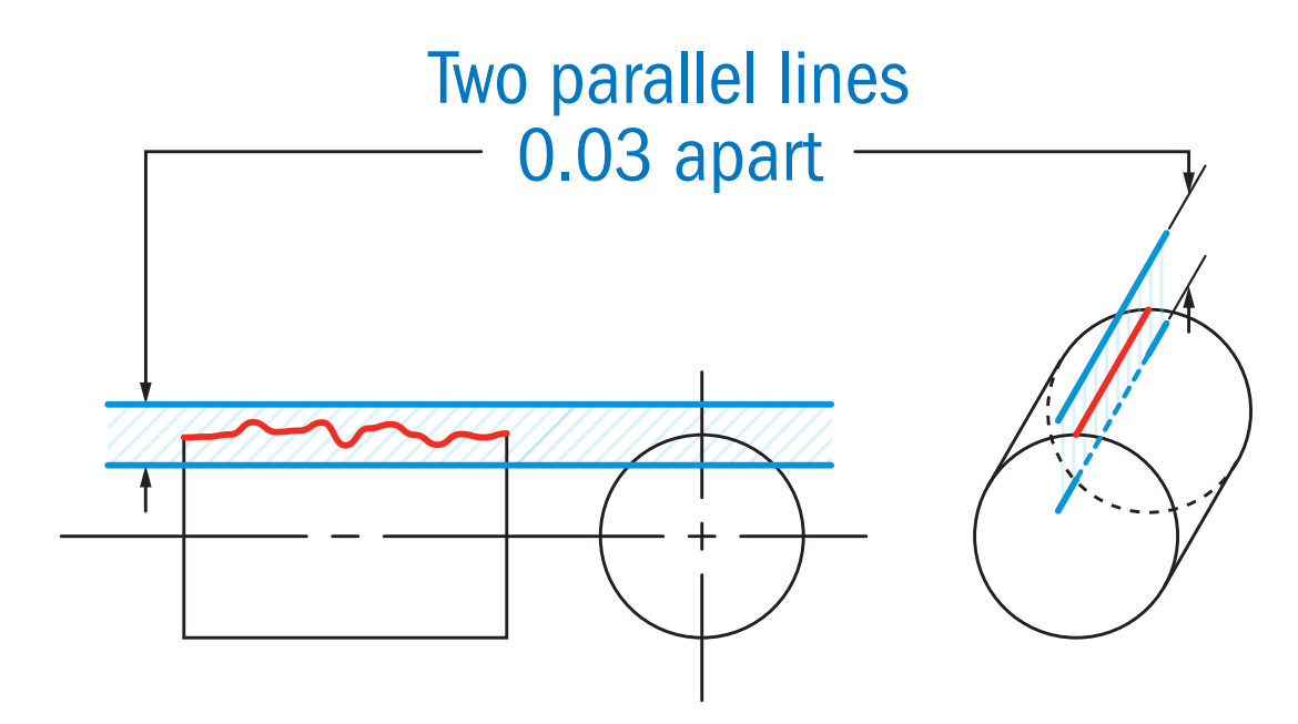
(GD&T basics) surface tolerance zone
Surface Straightness Requirements
Surface straightness GD&T applies to line elements on a nominally flat or cylindrical surface, controlling how much any individual line element in the specified direction can deviate from a straight line. It's commonly applied when a surface needs to make consistent contact along its length, sliding surfaces, sealing faces, bearing rails, and guide surfaces where a bowed surface would produce uneven contact pressure or clearance variation.
The control applies to line elements, not to the entire surface simultaneously. This is an important distinction, surface straightness doesn't control flatness. A surface can have good straightness in every individual line element while still being generally tilted, warped in a complex shape, or curved in one direction while straight in another. If the requirement is that the whole surface lies within a single plane, flatness is the correct control. Straightness is the correct control when the requirement is about individual line behavior, typically when a surface slides against a mating surface where contact length, not overall surface relationship, is what matters.
Surface Tolerance Zones
For surface straightness, the tolerance zone is established for each line element independently. The tolerance value defines the width of the zone, two parallel planes separated by the tolerance value, that each line element must fit within. The zone isn't fixed; it finds the orientation for each line element that minimizes deviation.
If the feature control frame specifies straightness in one direction, a 0.05mm straightness callout on a milled surface, the control applies to line elements parallel to the long axis of the surface in that direction. If straightness in both directions needs to be controlled, two separate callouts are required. The surface must meet both independently.
Common Surface Straightness Applications
Machine tool guideway surfaces where a straightness error produces positioning error throughout the travel range. Hydraulic cylinder bores where surface straightness affects seal behavior and lateral load distribution. Long shaft diameters where the surface line elements need to be straight for consistent contact with bearing races. Die and mold parting surfaces where straightness errors cause flashing.
Axis Straightness GD&T for Cylindrical Features
Axis Straightness Definition
Axis straightness GD&T controls the median line of a cylindrical feature, the line connecting the centers of all cross-sections along the feature's length.
This distinction matters for understanding what axis straightness GD&T allows and prohibits. A shaft with axis straightness tolerance of 0.1mm can have its median line deviate up to 0.1mm total within the cylindrical tolerance zone, the surface of the shaft can be wavy or have varying diameter, as long as the median line stays within that zone and the size tolerance is met simultaneously.
Straightness Control for Shafts and Holes
Shaft straightness is the most common axis straightness GD&T application. Long shafts that carry bending loads, run in multiple bearings, or need to pass through close-fitting holes in assemblies all benefit from explicit axis straightness control. Without it, a shaft that passes size tolerance could bow enough to prevent assembly or create bearing misalignment that the size tolerance didn't catch.
Hole straightness is less commonly called out explicitly because holes in machined parts are usually short enough that axis deviation is controlled adequately by the size tolerance and general machining accuracy. In deep bored holes, long drilled features, or precision bores where the bore axis must align precisely with a mating shaft over a long engagement length, axis straightness GD&T makes the requirement explicit.
Functional Importance in Assembly
The functional importance of axis straightness in assembly comes down to the effective clearance between a shaft and a hole over the full engagement length. A shaft and hole can both be within their individual diameter tolerances and still not assemble if the shaft axis bows enough to create interference at some point along the engagement.
The virtual condition concept in GD&T captures this. A shaft's virtual condition at maximum material condition (MMC) equals its maximum diameter plus its axis straightness tolerance, the worst-case envelope the shaft can occupy while still conforming to both tolerances simultaneously. The mating hole's virtual condition is its minimum diameter minus any applicable tolerances. For assembly to be guaranteed, the shaft's virtual condition must be smaller than the hole's virtual condition. Axis straightness GD&T on the shaft directly affects this calculation.
Selecting Straightness Tolerances in Engineering Drawings
Tight vs Loose Straightness Tolerances
Straightness tolerance selection starts with function. What happens if the feature isn't straight, does it affect assembly, load distribution, sealing performance, or fatigue life? The severity of those consequences determines how tight the tolerance needs to be.
Loose straightness tolerances, 0.1-0.5mm or more, are appropriate for non-critical features, long spans where small deviations have no functional consequence, and situations where the straightness error stays well within what the manufacturing process naturally produces. Tight straightness tolerances, 0.01-0.05mm, are appropriate for precision bearing seats, sliding contacts, sealing interfaces, and any feature where small deviations directly affect function or assembly.
Functional Requirements and Fit
The straightness tolerance needs to be tighter than the functional limit it protects. If assembly requires the shaft axis to deviate no more than 0.15mm over its length to ensure the shaft passes through a close-fitting bore, the axis straightness tolerance should be 0.1mm or less, providing engineering margin between the tolerance limit and the functional limit.
For mating features where axis straightness affects the virtual condition calculation, the tolerance needs to be selected in conjunction with the size tolerance to ensure the virtual condition analysis confirms assemblability at worst-case conditions.
Manufacturing Capability Limits
A straightness tolerance tighter than the manufacturing process can reliably hold produces parts that fail inspection at a high rate, which is more expensive than selecting a tolerance matched to the process.CNC turning of a steel shaft may typically achieve axis straightness in the range of 0.02-0.05 mm on capable production equipment, depending on part geometry, support, and process control. Demanding 0.005mm from turning without subsequent grinding adds cost and inspection burden without necessarily improving the functional outcome.
Practical manufacturing capability benchmarks: precision CNC turning on a well-maintained lathe may typically achieve axis straightness in the range of 0.02-0.05 mm on shafts up to about 300 mm long, depending on support conditions, material, and inspection method.Cylindrical grinding holds 0.005-0.01mm. Centerless grinding holds 0.005-0.015mm. Surface grinding holds surface straightness of 0.005-0.01mm per 300mm. Thread grinding and precision lapping can hold below 0.005mm on short spans.
What Causes Straightness Errors in Manufacturing
Tool Deflection and Cutting Forces
Turning a long shaft generates radial cutting forces that push the tool and the workpiece apart. The workpiece flexes away from the tool, the deflection is greatest at the midpoint of the unsupported span. The result is a shaft that's slightly larger in diameter at the center than at the ends, and whose axis bows in the direction opposite to the cutting force.
The magnitude of this deflection depends on the shaft's stiffness (diameter and material), the support conditions (chuck only vs chuck and tailstock vs between centers), the depth of cut, and the feed rate. A 25mm diameter steel shaft 300mm long supported at one end deflects roughly 0.05-0.15mm under moderate cutting forces. The same shaft supported between centers deflects a fraction of that. Understanding tool deflection as a straightness error source is the first step in controlling it.
Residual Stress and Material Movement
Raw material, bar stock, forgings, castings, contains residual stress from its production history. When machining removes material asymmetrically, it upsets the stress equilibrium and the part moves. A shaft turned from bar stock that had significant residual stress may measure straight immediately after machining and deviate 0.1mm or more after sitting overnight as the stress redistributes.
This stress relief movement is why roughing passes leave material for finishing, and why stress relief heat treatment is specified on precision shafts before finish machining. Rough turning disturbs the stress state and allows the bulk of the movement to occur. Finish turning after stress relief works on a materially stable part and produces dimensions and straightness that are stable in service.
Thermal Distortion During Machining
The workpiece warms during machining from cutting heat and friction. A cold shaft measured at 20°C expands when it warms to 35°C during machining, a 300mm steel shaft grows approximately 0.05mm in length and less in diameter, but the thermal expansion isn't perfectly uniform if the heat distribution isn't uniform. One end of the shaft near the chuck, which acts as a heat sink, stays cooler than the middle. The differential expansion bows the shaft.
For tight axis straightness requirements, machining with consistent flood coolant, allowing thermal stabilization between roughing and finishing, and measuring at a consistent temperature (20°C is the standard reference temperature for dimensional measurement) are all process controls that reduce thermal contribution to straightness error.
Fixturing and Process Stability
How the part is held during machining directly affects the straightness of the finished part. A shaft gripped in a three-jaw chuck with worn jaws gets held slightly off-center, every diameter the tool cuts is concentric with the spindle axis, but the part's geometric axis doesn't coincide with the spindle axis. The result is a shaft that appears straight but whose actual axis deviates from the nominal.
For precision axis straightness work, between-centers turning eliminates the chuck grip error entirely, the machining axis is defined by the centers, not by the chuck. Collet chucks produce better concentricity than three-jaw chucks for short parts. Four-jaw independent chucks allow precise truing of the part before cutting, which is appropriate for tight-tolerance work on parts that need to be precisely located.
GD&T Straightness Examples and Drawing Interpretation
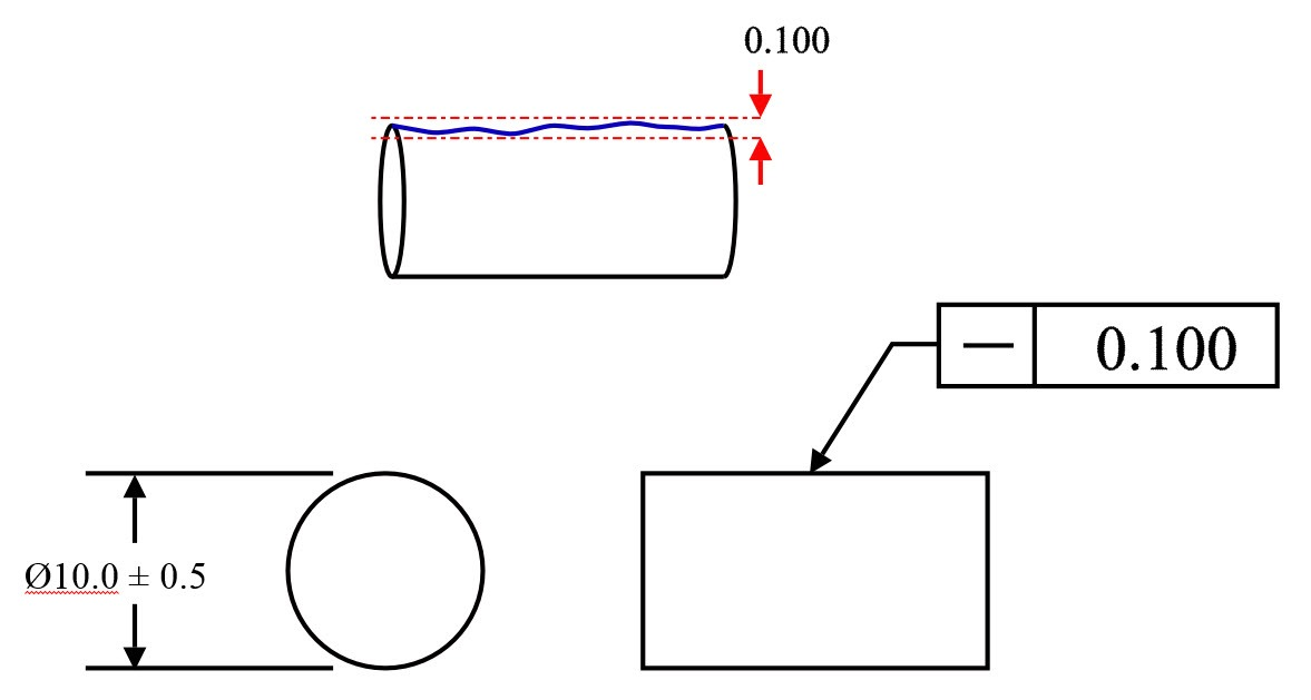
Surface Straightness Example
A machined aluminum rail 400mm long needs to maintain consistent contact with a sliding component along its length. The designer specifies surface straightness GD&T of 0.05mm on the top face of the rail.
Reading the callout: the feature control frame shows the straightness symbol (horizontal line), followed by 0.05. No datum is referenced. The leader connects to the top surface of the rail.
What this means in inspection: for every line element running along the top face parallel to the long axis, the inspector must verify that the line element fits within a 0.05mm wide zone, two parallel planes 0.05mm apart. Each line element is evaluated independently. A surface that curves 0.08mm across its width but has line elements that each stay within 0.05mm passes, the overall surface waviness is a different concern than the straightness of individual line elements.
Axis Straightness Example
A 30mm diameter steel shaft 200mm long needs to pass through two close-fitting bores in a housing. The designer specifies axis straightness GD&T of 0.1mm diameter on the shaft diameter dimension.
Reading the callout: the feature control frame shows the straightness symbol, followed by the diameter symbol (⌀) and 0.1. The frame is associated with the 30mm diameter dimension. No datum reference.
In inspection, this means the shaft’s derived median line, established from the centers of cross-sections along its length, must lie within a cylindrical tolerance zone 0.1 mm in diameter. The cylinder is oriented by best-fitting to the median line data, not fixed to a datum. If the median line's total spread in the best-fit position exceeds 0.1mm, the shaft fails the straightness requirement regardless of whether every diameter measurement is within the 30mm size tolerance.
Common Interpretation Mistakes
Treating surface and axis straightness as interchangeable, they use the same symbol but control completely different things; applying the wrong interpretation to a callout produces a tolerance zone with the wrong shape and the wrong verification method.
Adding a datum reference to a straightness callout, straightness never references a datum; if a datum appears, the callout has been changed to a different geometric control (likely parallelism) without the symbol being updated.
Confusing straightness tolerance value with tolerance zone diameter, for axis straightness, the tolerance value is the diameter of the cylindrical zone, not the radius; a 0.1mm tolerance is a 0.1mm diameter zone, which means the median line can deviate ±0.05mm from center.
Applying surface straightness to an axis, surface straightness controls line elements on surfaces; it can't be used to control the axis of a cylindrical feature, which requires the feature control frame to be associated with the diameter dimension.
Assuming Rule #1 eliminates the need for axis straightness, Rule #1 applies to features of size by requiring perfect form at MMC unless otherwise specified. Axis straightness, especially when applied with MMC, adds an explicit control on the derived median line and must be interpreted together with the size limits and applicable ASME Y14.5 rules.
Need straightness-critical shafts, rails, or precision components? JLCCNC delivers CNC machined parts with tight GD&T control, detailed inspection, and fast turnaround. Upload your CAD file and get a quote today.
Precision CNC Machining Service
Professional manufacturing, fast turnaround, and quality assurance.
Measuring and Inspecting Straightness
How Straightness Is Measured
Surface straightness is commonly checked with a dial indicator, straight edge, or surface plate setup. The indicator traverses along the controlled line element, and the total variation is compared with the specified tolerance.
Axis straightness is more complex because the requirement applies to the derived median line rather than the visible surface. For precision verification, CMM measurement is the preferred method. The CMM probes multiple cross-sections, calculates their centers, and evaluates whether the derived median line fits within the required cylindrical tolerance zone.
Shop-floor methods such as V-blocks and dial indicators can be useful for process checks on shafts, but they do not directly verify axis straightness per GD&T because the readings also include effects from surface variation, roundness, and setup conditions.
Inspection Planning and Cost
Straightness tolerances should be specified together with a realistic inspection method. A loose straightness tolerance may be verified quickly with simple indicator-based inspection, while a tight axis straightness requirement may require CMM evaluation or a functional gauge.
Inspection cost increases as the tolerance becomes tighter and the evaluation method becomes more complex. For that reason, the most cost-effective practice is to apply the loosest straightness tolerance that still protects the feature’s functional requirement, and to reserve very tight controls for the features that truly need them.
Straightness GD&T vs Other Geometric Tolerances
| Factor | Straightness | Flatness | Parallelism | Runout |
|---|---|---|---|---|
| What it controls | Line elements or median axis | Entire surface plane | Orientation relative to datum | Surface deviation from axis rotation |
| Datum required | No | No | Yes | Yes |
| Tolerance zone shape | Two planes (surface) or cylinder (axis) | Two parallel planes | Two parallel planes | Cylindrical zone around datum axis |
| Applies to | Line elements, cylindrical axes | Planar surfaces | Planar surfaces or axes | Cylindrical or planar surfaces |
| MMC applicable | Yes (axis only) | No | Yes | No |
| Inspection method | Indicator traverse or CMM median line | Surface plate and indicator | CMM or indicator with datum | Dial indicator on rotating part |
| Controls shape | Yes | Yes | No (controls orientation) | No (controls dynamic behavior) |
| Controls orientation | No | No | Yes | Partially |
| Controls location | No | No | No | No |
| Refines size tolerance | Yes | Yes | No | No |
Best Practices for Controlling Straightness
Reducing Material Distortion
Rough machine first, then allow stress relief before finish machining. For aluminum, aging or natural stress relief overnight between roughing and finishing is standard practice on precision parts. For steel, controlled stress relief at 550-650°C followed by slow cooling eliminates most residual stress before finish operations. Parts that need tight axis straightness should be rough-turned to within 1-2mm of final diameter, stress-relieved, then finish-turned to final size, this sequence produces parts whose dimensions and straightness are stable after machining.
Material selection matters too. Free-machining grades with uniform microstructure, 1215 steel, 6061-T6 aluminum, produce better straightness consistency in turning than alloys with pronounced banding or segregation that create differential machining resistance along the cut.
Optimizing Machining Parameters
Between-centers turning eliminates chuck grip eccentricity and produces the best axis straightness on long shafts. Steady rest support at midspan prevents sag and reduces deflection-induced diameter variation on shafts where the length-to-diameter ratio exceeds 8:1.
Light finish passes, 0.1-0.3mm depth of cut, reduce cutting force and therefore workpiece deflection on the finish operation that determines the final straightness. Taking the finish pass at low feed rate (0.05-0.1mm/rev) with a sharp insert maintains cutting force consistency and surface finish simultaneously. Running constant surface speed during the finish pass keeps the cutting conditions consistent across diameter changes on stepped shafts.
FAQs About Straightness GD&T
Q: What is straightness in GD&T?
Straightness GD&T is a form control that limits how much a line element on a surface, or the derived median axis of a cylindrical feature, can deviate from a theoretically perfect straight line. It uses a horizontal line symbol and never requires a datum reference.
Q: What is the GD&T straightness symbol?
A single horizontal line, the simplest symbol in GD&T. It appears in the first compartment of a feature control frame, followed by the tolerance value. No datum reference compartments follow. If a diameter symbol (⌀) precedes the tolerance value, the tolerance zone is cylindrical and the control applies to the feature axis rather than to surface line elements.
Q: What is the difference between surface and axis straightness?
Surface straightness controls individual line elements on a surface. Axis straightness controls the derived median line of a cylindrical feature within a cylindrical tolerance zone.
Q: How is straightness tolerance measured?
Surface straightness is measured by traversing a dial indicator along the surface and recording the total deviation across the traverse length. Axis straightness is measured by CMM, the machine probes multiple cross-sections, calculates their centers, extracts the median line, and evaluates how far the median line deviates from a best-fit straight line. Functional gauges check virtual condition for axis straightness at MMC.
Q: Does straightness require a datum?
No. Straightness is a form control, so it does not reference a datum.
Popular Articles
• Cutting with Precision: A Comprehensive Guide to CNC Water Jet Technology
• CNC Coolant Explained: Types, Maintenance & Safety
• Rake Angle in Machining: Machinists’ Guide to Perfect Cuts
• What Steps Are Taken To Minimize Waste In CNC Machining Processes?
• How EDM Wire Cutting Works: Complete Guide to Precision CNC Wire Cutting
Keep Learning
Chatter in Machining: Causes, Effects, and How to Reduce It
CNC milling operation producing visible chatter marks on an aluminum workpiece Quick Chatter Diagnosis Checklist Symptom Most Likely Cause First Action High-pitched squeal Regenerative chatter Change spindle speed ±15% Chatter only in deep pockets Excessive tool overhang Shorten tool Chatter on thin walls Low workpiece rigidity Improve fixturing Chatter after tool replacement Runout / holder issue Check tool holder Chatter only during finishing DOC too small / rubbing Increase feed or adjust speed It ......
What Is Tool Offset in CNC? Types, Setup & Best Practices
CNC tool offset setup with measurement overlay Key Takeaways CNC offsets connect programmed intent with actual cutter position. Length data guides Z-axis depth control. Radius data protects part size during contour milling. Geometry values define the cutter's measured baseline. Wear values support fine correction during production. Verified data lowers scrap risk before full machining. Good offset habits protect tools, fixtures, and parts. In the context of CNC machining , tool offset is the quiet set......
Trochoidal Milling: Complete Guide to High-Efficiency CNC Machining
Key Takeaways Trochoidal milling combines circular cutter motion with continuous forward feed. The cutter normally engages 5 to 20% of its diameter instead of making a full-width cut. A smaller engagement angle limits force changes during slotting and pocket roughing. Low radial engagement often allows greater axial depths of cut than conventional slot milling. CAM software calculates the circular path automatically from the selected machining parameters. This strategy is widely applied to titanium, s......
What Is Die Casting? Process, Materials, and Applications
Key Takeaways Die casting is a metal casting process that forces molten metal into a reusable steel mold under high pressure, producing parts with tight tolerances and good surface finish at high volume. Aluminum die casting is the most common form by far, thanks to its combination of light weight, decent strength, and good corrosion resistance. The die casting process runs through mold preparation, injection, cooling, and ejection in a cycle that can repeat every few seconds to minutes depending on p......
First Angle vs Third Angle: Understanding Orthographic Projection Methods
Key Takeaways Orthographic projection is the system that lets a 3D part be represented through multiple 2D views, front, top, side, and so on. First angle projection and third angle projection are the two standard methods for arranging those views, and they place views in opposite positions relative to the object. First angle projection is the ISO standard used across most of Europe, India, China, Russia, and many other countries following ISO standards Third angle projection is the standard in the Un......
Micro EDM Machining: Capabilities, Materials, and Applications for Precision Components
Key Takeaways About Micro EDM Machining Only electrically conductive materials can be machined. Hole diameters can reach below 50 μm on specialized equipment. The process produces almost no mechanical cutting force, making it suitable for thin or delicate features. Surface integrity still requires attention because recast layers and heat-affected zones may remain after machining. Micro EDM is often combined with CNC machining, with milling producing the main geometry before EDM finishes critical micro......