Depth of Cut in CNC Machining: Definition, Calculation, and Process Optimization
13 min
- What Is Depth of Cut in CNC Machining?
- Axial Cutting vs Radial Cutting
- Why Depth of Cut Matters in CNC Machining
- How Depth of Cut Is Determined
- How to Calculate Depth of Cut
- Depth of Cut in Different Machining Operations
- End Mill Depth of Cut Guidelines
- Typical Depth of Cut Ranges by Material
- Depth of Cut and Machining Strategy
- Common Problems Caused by Incorrect Depth of Cut
- Depth of Cut vs Other Cutting Parameters
- Conclusion About Depth of Cut
- FAQ About Depth of Cut
Key Takeaways About Depth of Cut
- Depth of cut defines how much material a tool removes per pass and sets the pace for machining operations.
- Axial and radial engagement interact to determine cutter contact, influencing tool load and part accuracy.
- Material hardness, wall thickness, and feature geometry affect how aggressively a cut can be applied.
- Cutting too deep or too shallow can cause tool wear, surface marks, or extended cycle time.
- Test cuts and CAD review help verify depth of cut for each part before full production.
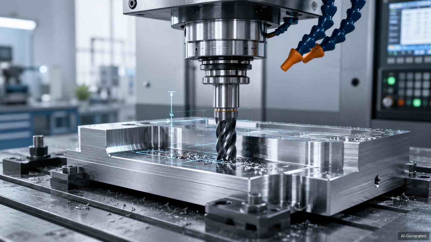
CNC milling tool showing depth of cut on metal part
In CNC machining, depth of cut is one of those choices that guides the entire job. Excessive depth of cut can cause problems for the tool, machine, and workpiece. Stay too cautious and production drags. Depth of cut works best when it matches the material, cutter, setup, and finish goal and gives engineers a lever for balancing output with dependable results.
What Is Depth of Cut in CNC Machining?
Depth of cut is the amount of material a CNC tool removes below the earlier surface during one pass. It gives the program a set removal amount before the cutter moves on.
How It Is Measured
Machinists read the value in millimeters or inches, which might be taken from the prior surface to the machined level in the tool's working direction.
Difference From Cutting Width (Stepover)
Cutting width, also known as stepover, defines lateral engagement. It describes sideways cutter engagement, but depth of cutting describes downward engagement. This keeps the two terms separate in milling notes.
Axial Cutting vs Radial Cutting
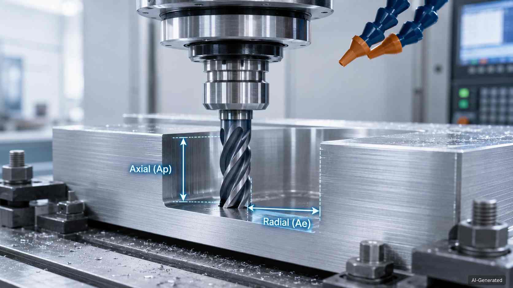
Axial and radial depth of cut in CNC milling
What Is Axial Depth of Cut (Ap)
In milling operations, axial depth of cut (Ap) describes how deeply the cutter engages the material along the tool axis. This is sometimes referred to as axial cutting depth in machining documentation.
What Is Radial Depth of Cut (Ae)
Radial depth of cut (Ae) describes side engagement across the cutter's diameter. This shows how much of the edge enters the material from one lateral pass to another.
How Axial and Radial Engagement Work Together
Together, Ap and Ae affect the cutter's contact area, which makes depth of cut less about one number and more about how the tool meets the work from two directions.
Why Depth of Cut Matters in CNC Machining
Material Removal Rate and Productivity
When more stock leaves each pass, output can rise without extra toolpaths. However, the shop still has to keep the spindle, coolant, and setup within a steady working range.
Cutting Forces and Machine Load
Whenever the depth of cut increases, the tool asks more from the spindle and structure, which renders the machine load an early warning sign during any demanding cut.
Tool Life and Wear
Increased depth of cut raises heat and accelerates tool wear. It makes inserts or end mills wear prematurely when the selected setting outruns the tool's comfort zone.
Surface Finish and Dimensional Accuracy
Surface finish and dimensional accuracy are also affected by depth of cut. Excessive engagement can increase tool deflection, vibration, and thermal loading, leading to visible tool marks, dimensional drift, or geometric error on critical features.
How Depth of Cut Is Determined
Workpiece Material Properties
Material properties are one of the primary factors affecting depth of cut selection. Aluminum allows a deeper bite. However, stainless, titanium, or hardened steel need a gentler entry to keep the pass under control.
Tool Diameter and Tool Geometry
Tool diameter and geometry further influence the allowable depth of cut. The end mill depth of cut rule of thumb can help at the start. But diameter, flute count, edge prep, reach, and coating decide where the first trial belongs. Finishing employs between 3 and 5 percent of the cutter diameter as radial engagement for peripheral milling, but severe roughing may reach 30 to 50 percent of the cutter diameter.
Machine Rigidity and Available Power
After the tool, the machine sets another boundary. Spindle power, axis drive capacity, holder grip, and column stiffness decide whether the selected setting runs calmly.
Workholding Stability
Workholding stability also limits allowable cutting engagement. The reason might be that thin walls, long overhangs, jaws, clamps, and vise contact can limit how much pressure the part can take.
Balancing DOC With Feed Rate and Cutting Speed
Programmers adjust the depth of cut alongside feed rate and cutting speed. Chip shape, spindle vibration feedback, and trial cut data guide final parameter adjustments.
How to Calculate Depth of Cut
Milling Calculation
In milling, depth of cut is measured as the vertical distance between the original surface and the machined surface after a single pass.
For example, if the workpiece surface starts at Z0 and the tool machines down to Z-2 mm, the depth of cut is 2 mm.
DOC = |Zinitial − Zfinal|
Where:
- DOC = depth of cut
- Zinitial = original surface position
- Zfinal = machined surface position
Lathe Calculation
In turning operations, depth of cut is calculated from the change in workpiece diameter.
DOC = (Dinitial−Dfinal)/2
Where:
- DOC = depth of cut
- Dinitial = starting diameter
- Dfinal = finished diameter
For example, if a shaft diameter is reduced from 50 mm to 46 mm:
DOC = (50−46)/2 = 2 mm
The tool removes 2 mm radially from the surface during the pass.
Link to Material Removal Rate
Depth of cut directly influences material removal rate (MRR) because it determines how much material is engaged during each pass. Increasing depth of cut can improve productivity, but only if machine power, tool rigidity, and chip evacuation remain within stable operating limits.
For milling operations, a simplified MRR equation is:
MRR = Ap × Ae × Feed Rate
Where:
MRR = Material Removal Rate
Ap = Axial Depth of Cut
Ae = Radial Depth of Cut
Feed Rate = Tool feed per minute
Depth of Cut in Different Machining Operations
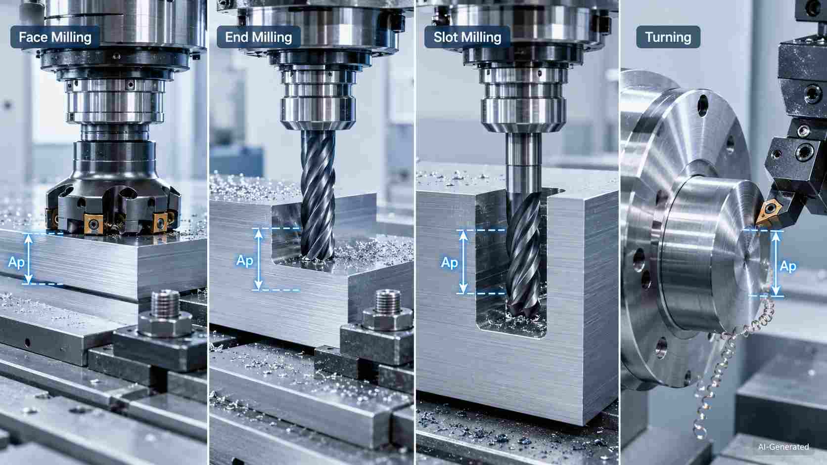
CNC depth of cut across milling and turning operations
Face Milling
In face milling, depth of cut might remain modest while the cutter sweeps broad flat areas. Thus, it helps the pass leave an even plane without crowding the inserts.
End Milling
End milling allows the tool to engage pockets, walls, and contours with full depth consideration. This is because pockets, walls, and contours each ask for engagement that matches reach, corner shape, and stock around the flute.
Slot Milling
A slot asks more from the full cutter width, which makes axial cutting and chip evacuation worth additional attention during narrow channel work.
CNC Lathe Operations
On a CNC lathe, radial infeed removes a ring of stock from the outside or inside diameter. Roughing and final passes are separated by the part tolerance.
End Mill Depth of Cut Guidelines
Common Rule-of-Thumb Recommendations
An end mill depth of cut rule of thumb provides a starting range rather than a guarantee. You should approach it as if it were a shop note that has to be verified on the machine. For the context of slotting, ordinary end-mill edges may have Ap values ranging from 0.05 to 0.2xD. On the other hand, roughing or semi-finishing edges may have Ap values as high as 1xD. For finishing operations, axial depth may be a small fraction of tool diameter, while roughing cuts can approach or exceed the cutter diameter depending on tool design, machine rigidity, and cutting strategy.
Why Tool Diameter Matters
Larger cutters generally provide greater core strength and stiffness, allowing higher depth of cut values. On the other hand, a slim cutter asks for shorter reach and gentler entry.
Full-Width vs Light Radial Engagement
Full-width cutting surrounds the tool with more contact. Nevertheless, light radial engagement allows the edge to work with a narrower bite and easier chip exit.
When Recommended Values Should Be Adjusted
Make adjustments to the depth of cut if the tool protrudes by a significant amount, the material is sticky, the pocket is deep, or the wall of the component starts to bend.
Validating Parameters Through Test Cuts
With the help of chip color, spindle sound, edge condition, and measured part reaction, a trial pass offers the opportunity to validate the selection before the actual work is carried out.
Typical Depth of Cut Ranges by Material
While tool diameter and machining strategy establish practical limits, material properties often determine the final allowable depth of cut. The values below are commonly used starting points for CNC milling operations and should be verified through test cuts and tooling recommendations.
| Material | Typical Roughing Axial DOC (Ap) | Notes |
|---|---|---|
| Aluminum Alloys | 0.5D–2D | Supports deeper engagement because cutting forces are relatively low |
| Mild Steel | 0.5D–1D | Depends on cutter rigidity and spindle power |
| Stainless Steel | 0.3D–1D | Higher cutting forces and heat generation often require reduced engagement |
| Titanium Alloys | 0.2D–0.8D | Conservative values help control heat and tool wear |
| Hardened Steel (>45 HRC) | 0.05D–0.2D | Tool life and machine stability become the primary limitations |
Where D represents cutter diameter.
For example, a 10 mm end mill roughing aluminum may use an axial depth of cut between 5 mm and 20 mm, while the same tool machining titanium may operate between 2 mm and 8 mm, depending on the toolpath strategy and machine capability.
Recommended depth of cut values provide a starting point. Thin walls often require smaller axial passes, while deep pockets can restrict how far the cutter moves sideways. Uploading your CAD file allows the machining team to review parameters and adjust cuts before the first trial.

Precision CNC Machining Service
Professional manufacturing, fast turnaround, and quality assurance.
Depth of Cut and Machining Strategy
Roughing for Maximum Material Removal
Roughing prioritizes the removal of bold stock and enables the depth of cut to carry more of the workload while the program leaves a safe allowance for later sizing.
Semi-Finishing Operations
Semi-finishing is performed after roughing to smooth out the leftover stock and provide the subsequent toolpath with a more consistent allowance before the final pass starts.
Finishing Passes for Surface Quality
When finishing, the pass becomes lighter and more cautious, with the goal of obtaining texture, size control, and edge detail rather than removing much of the stock.
High-Efficiency Machining Strategies
Modern adaptive milling strategies often combine low radial engagement with deeper axial cutting to maintain a consistent chip load and improve material removal rates.
Common Problems Caused by Incorrect Depth of Cut
Excessive Tool Deflection
When cutting forces exceed tool's stiffness to carry more load than its stiffness allows. In that case, the edge bends away and leaves tapered walls or out-of-size features.
Chatter and Vibration
Not only that, but unstable engagement can start chatter, and that is the moment when repeated vibration marks the surface and sends harsh noise through the setup.
Premature Tool Wear
The depth of cut may limit the life of an insert or cutter by causing chipped corners, rubbing zones, and uneven wear patterns. This occurs when the amount of stress continues to increase.
Low Productivity and Excessive Cycle Time
Excessively cautious depth of cutting leaves extra stock for repeated passes, which in turn extends the cycle time and increases the cost per part.
Depth of Cut vs Other Cutting Parameters
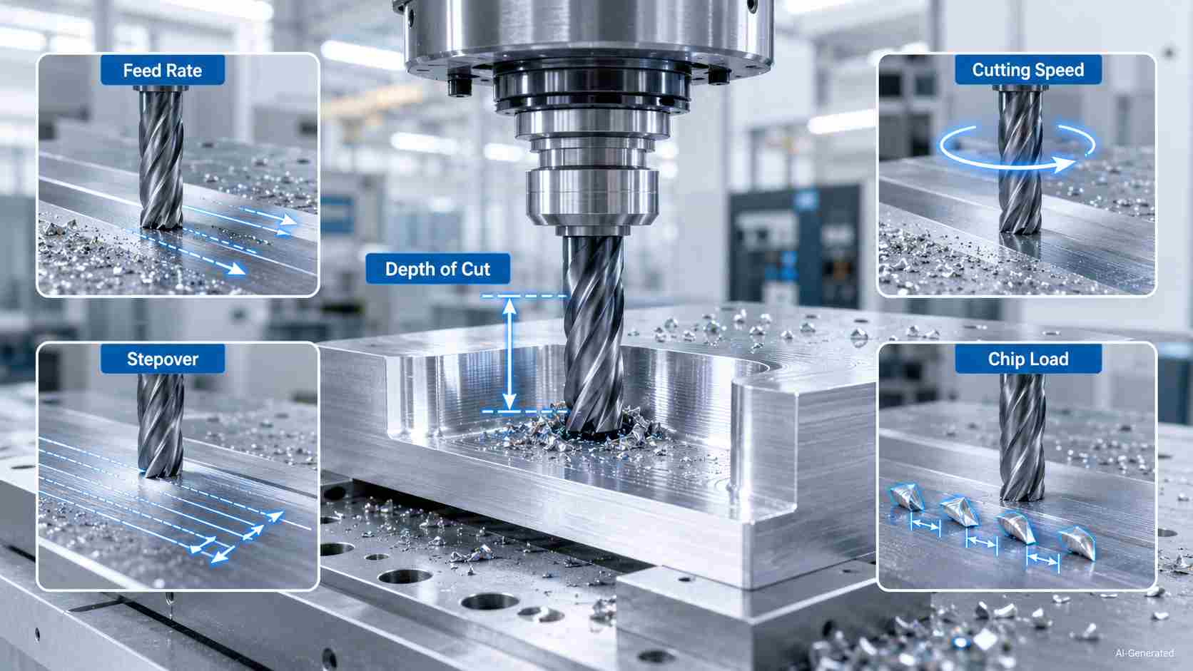
CNC depth of cut with feed, speed, stepover, chip load
Depth of Cut vs Feed Rate
Let's begin with the feed rate. It sets travel per minute or per tooth. At the same time, the engagement size sets how much material the edge carries through each pass.
Compared With Cutting Speed
Cutting speed describes the surface velocity at the cutting edge. Increasing cutting speed while maintaining a large depth of cut can raise heat generation and tool wear even when feed and spindle load appear acceptable.
Compared With Stepover
Stepover works across the path, not downward into it. Moreover, its share of cutter contact changes chip thickness even when the vertical entry remains unchanged.
Compared With Chip Load
Chip load brings each tooth into the picture, linking feed, flute count, and spindle rpm. When the depth of cutting changes, the best setting may need a matching edit rather than a guess.
Conclusion About Depth of Cut
Depth of cut is not a fixed value pulled from a chart. A setting that works well in aluminum may be completely unsuitable for stainless steel or titanium, even when the same cutter is used.
Successful machining depends on finding a depth of cut that the machine, tooling, and workholding can support consistently. When the balance is right, material removal remains efficient without creating unnecessary tool wear or process instability.
JLCCNC provides CNC machining services for prototype and production parts. Upload a CAD file to receive an instant quotation and manufacturing review.
Precision CNC Machining Service
Professional manufacturing, fast turnaround, and quality assurance.
FAQ About Depth of Cut
Q: What is the depth of cut in CNC machining?
It is the programmed engagement value that tells a CNC tool how much stock to remove during a pass, which might be written in millimeters or inches for the job setup.
Q: What is the maximum depth of cut for an end mill?
The maximum depth of cut depends on the cutter diameter, flute length, material hardness, and machine stability. For most end mills, axial depth rarely exceeds the tool’s flute length. Roughing passes can push deeper engagement if the cutter and machine are rigid, but exceeding recommended depth risks tool deflection, chatter, and poor surface finish. Always verify with trial cuts and manufacturer guidelines for the specific end mill.
Q: What is axial cutting?
Axial cutting refers to material removal along the tool axis. In milling, axial cutting depth (Ap) determines how deeply the cutter engages the workpiece during a pass.
Q: What is the difference between axial and radial depth of cut?
Axial engagement follows the cutter's centerline. On the other hand, radial engagement runs across the cutter width and gives milling two separate directions of contact.
Q: How does depth of cut affect tool life?
While a higher setting may increase the amount of edge pressure and heat, which can cause the cutting edge to wear out sooner, a lower setting can help the tool endure for longer.
Q: What is a typical end mill depth of cut?
A typical value depends on cutter diameter, flute length, material, holder, and setup, which is why catalog data and shop trials are more important than one universal number.
Q: Does increasing depth of cut always improve productivity?
No, more engagement can remove extra stock per pass. Nonetheless, poor stability, heat, or tool strain may erase that gain through slower recovery and inspection delays.
Q: How is the depth of cut different from stepover?
When we talk about stepover, we are referring to the sideways spacing between successive cutter paths. However, depth refers to the tool's penetration into the workpiece.
Q: How do machinists determine the correct depth of cut?
They review material behavior, cutter size, tool reach, holder grip, machine capacity, fixture support, and target tolerance before approving the value for production.
Q: Are different cut depths used for roughing and finishing?
Yes. Roughing operations generally use larger cut depths to maximize material removal, while finishing passes rely on smaller cut depths to improve surface finish and dimensional accuracy.
Popular Articles
• Cutting with Precision: A Comprehensive Guide to CNC Water Jet Technology
• CNC Coolant Explained: Types, Maintenance & Safety
• Rake Angle in Machining: Machinists’ Guide to Perfect Cuts
• What Steps Are Taken To Minimize Waste In CNC Machining Processes?
• How EDM Wire Cutting Works: Complete Guide to Precision CNC Wire Cutting
Keep Learning
Chatter in Machining: Causes, Effects, and How to Reduce It
CNC milling operation producing visible chatter marks on an aluminum workpiece Quick Chatter Diagnosis Checklist Symptom Most Likely Cause First Action High-pitched squeal Regenerative chatter Change spindle speed ±15% Chatter only in deep pockets Excessive tool overhang Shorten tool Chatter on thin walls Low workpiece rigidity Improve fixturing Chatter after tool replacement Runout / holder issue Check tool holder Chatter only during finishing DOC too small / rubbing Increase feed or adjust speed It ......
What Is Tool Offset in CNC? Types, Setup & Best Practices
CNC tool offset setup with measurement overlay Key Takeaways CNC offsets connect programmed intent with actual cutter position. Length data guides Z-axis depth control. Radius data protects part size during contour milling. Geometry values define the cutter's measured baseline. Wear values support fine correction during production. Verified data lowers scrap risk before full machining. Good offset habits protect tools, fixtures, and parts. In the context of CNC machining , tool offset is the quiet set......
Trochoidal Milling: Complete Guide to High-Efficiency CNC Machining
Key Takeaways Trochoidal milling combines circular cutter motion with continuous forward feed. The cutter normally engages 5 to 20% of its diameter instead of making a full-width cut. A smaller engagement angle limits force changes during slotting and pocket roughing. Low radial engagement often allows greater axial depths of cut than conventional slot milling. CAM software calculates the circular path automatically from the selected machining parameters. This strategy is widely applied to titanium, s......
What Is Die Casting? Process, Materials, and Applications
Key Takeaways Die casting is a metal casting process that forces molten metal into a reusable steel mold under high pressure, producing parts with tight tolerances and good surface finish at high volume. Aluminum die casting is the most common form by far, thanks to its combination of light weight, decent strength, and good corrosion resistance. The die casting process runs through mold preparation, injection, cooling, and ejection in a cycle that can repeat every few seconds to minutes depending on p......
First Angle vs Third Angle: Understanding Orthographic Projection Methods
Key Takeaways Orthographic projection is the system that lets a 3D part be represented through multiple 2D views, front, top, side, and so on. First angle projection and third angle projection are the two standard methods for arranging those views, and they place views in opposite positions relative to the object. First angle projection is the ISO standard used across most of Europe, India, China, Russia, and many other countries following ISO standards Third angle projection is the standard in the Un......
Micro EDM Machining: Capabilities, Materials, and Applications for Precision Components
Key Takeaways About Micro EDM Machining Only electrically conductive materials can be machined. Hole diameters can reach below 50 μm on specialized equipment. The process produces almost no mechanical cutting force, making it suitable for thin or delicate features. Surface integrity still requires attention because recast layers and heat-affected zones may remain after machining. Micro EDM is often combined with CNC machining, with milling producing the main geometry before EDM finishes critical micro......