What Is Stepover in CNC Machining? Meaning, Surface Finish, and Toolpath Strategy
14 min
- What Stepover Means in CNC Toolpaths?
- Why Stepover in CNC Matters for Machining Outcomes
- Stepover in Different Machining Strategies
- How Tool Geometry Changes Stepover Behavior?
- How to Choose Stepover in CNC Machining Jobs?
- Common Stepover Mistakes in CNC Machining!
- Stepover vs Stepdown!
- Conclusion About Stepover
- FAQs About Stepover
Stepover in CNC machining refers to the lateral distance a cutting tool moves between successive passes. It is a key parameter in CNC toolpaths that directly affects surface finish, machining time, and tool wear.
Understanding what stepover in CNC means is essential for optimizing both roughing and finishing operations in milling processes.
What Stepover Means in CNC Toolpaths?
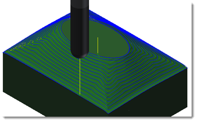
CAM toolpath illustrating stepover in CNC machining. (Source: chrisandjimcim.com)
Efficient milling requires long-term precision and full control over cutter engagement. Radial offset is the parametric value that determines how a solid carbide tool cuts through raw material. This parameter must be defined precisely in CAM systems. Miscalculating this distance can compromise part tolerances and break expensive end mills. Therefore, programmers must derive this dimension mathematically rather than relying on default software values.
What Is Stepover? (Definition for CNC Machining)
Stepover dictates the lateral distance a cutting tool shifts between successive milling passes. This specified radial engagement determines how much material is left uncut. Controlling this distance allows programmers to effectively manage cycle times and tool loads until the toolpath clears the defined boundary.
Relationship to Tool Diameter (Percentage-Based Input)
Radial offsets are typically calculated as a percentage of the cutting tool's total diameter. For example, a 0.500-inch flat end mill with a 50% stepover yields 0.250 inches of lateral movement. This proportional model enables programmers to apply consistent cutting strategies across diverse tool libraries.
1. Heavy Roughing Parameters: Traditional roughing may use 40–60% stepover, while high-efficiency milling typically uses lower radial engagement (10–25%) with higher feed rates. High-efficiency milling typically combines low radial engagement with high axial depth of cut.
2. Setting Precision Finishing Parameters: Profile cuts need a closer 0.05 to 0.15 offset ratio in order to significantly reduce visible machining marks.
Where Stepover Appears in CAM Settings?
CAM software packages locate radial offset inputs within specific toolpath menus. For instance, Mastercam refers to it as the "radial depth of cut," whereas Fusion 360 nests it within its "adaptive clearing" parameters.
Stepover in Siemens NX Configuration: This appears only under the Path Settings and strictly functions as the Stepover value.
SolidCAM Integration: The software shows this directly as the overlap parameter in the individual geometry clearing dialog.
GibbsCAM Interface: The system explicitly defines this as the cut width variable controlling the pocketing algorithms.
Why Stepover in CNC Matters for Machining Outcomes
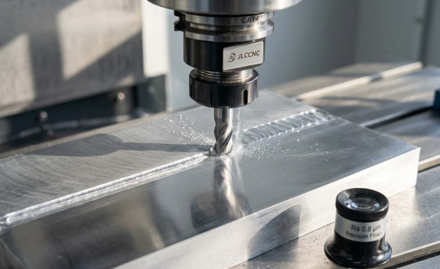
CNC end mill machining an aluminum surface (AI-generated)
Machine shops operate on the edge, and they balance between fast cycle times and tight customer dimensional tolerances. The radial offset value controls both production speed and final surface topography at the same time. According to an AccTek CNC expert, "A larger stepover increases machining speed but may leave visible tool marks." If operators want to optimize a machine program, this is the exact variable they need to carefully adjust.
Does your shop floor operate lights-out manufacturing where tool wear imposes strict production constraints? Radial control is the dedicated solution, and it allows for predictable and continuous high-volume production.
Surface Finish: How Stepover Creates Scallop Height?
Milling with a ball nose cutter leaves distinct ridges of unmachined material. These residual ridges are called scallops, and their height determines the surface roughness (Ra) value. Scallop height is typically calculated based on tool radius and stepover, which directly links stepover to surface roughness.
A larger lateral offset produces larger scallops, which may require secondary polishing. Reducing the offset value decreases ridge height, improving the surface finish.
Peak-To-Valley Measurement: This is the absolute physical distance from the scallop crest down to the machined valley floor.
Surface Roughness Average (Ra): This represents the arithmetic average of surface heights measured over a specified sample length.
No Need For Secondary Abrasive Finishing Operations: Tight radial shifts make it unnecessary to carry out multiple phases of polishing.
Stepover Formula and Calculation (Scallop Height Explained)
In CNC machining, stepover directly determines the scallop height left between tool passes, especially when using ball nose end mills.
The relationship can be approximated by:
h ≈ s² / (8R)
Where:
- h = scallop height
- s = stepover
- R = tool radius
This formula shows that scallop height increases with the square of stepover. Even a small increase in stepover can significantly worsen surface finish.
For this reason:
- Small stepover values are required for high-quality surface finishing
- Larger stepover values are acceptable for roughing operations
Machining Time and Efficiency Trade-Off
Cycle time impacts profitability. Reducing stepover increases toolpath length, often non-linearly depending on geometry. Programmers must find a balance between speed and surface quality, selecting the highest engagement value that meets the part's geometric specifications.
Tool Load, Wear, and Heat Distribution
Radial engagement affects how the cutter handles heat and wear. High-efficiency milling strategies often use smaller offset ratios to maintain a low chip thickness and evacuate heat effectively. Lighter radial cuts paired with appropriate feed rates help avoid tool deflection. This strategy maintains a consistent chip load, improving tool longevity.
Case 1 Aerospace Titanium Processing:
A machinist runs a 0.500-inch end mill through titanium with a 0.50 ratio engagement, which can lead to excessive heat buildup and rapid tool wear. The use of a lighter 0.10 radial cut with high feed rates also avoids tool deflection completely. This strategy keeps a consistent chip load, and this allows for several times the life of the tool.
Stepover in Different Machining Strategies
Radial tool engagement for milling operations differs by operation entirely across the manufacturing floor. A bulk material removal mindset is not compatible with a precision 3D contouring process.
Understanding stepover behavior across toolpath types helps reduce scrap and tool failure. We dynamically modify these parameters depending on the exact part of the manufacturing process we are in.
Roughing Toolpaths (High Stepover for Material Removal)
Roughing operations remove material volume efficiently. Toolpaths for flat-bottom end mills use higher engagement ratios to utilize more of the flute length. This approach clears pockets quickly but leaves stepped walls requiring finishing passes.
Heavy Material Removal Tactics: This is called traditional pocket milling, as constant heavy engagement means feed rates have to scale down enough to endure corner loading spikes.
Trochoidal Milling: The software dynamically morphs the lateral shift distance while keeping spindle loads perfectly constant.
Internal Inserted Flutes: The use of specific insert geometry requires huge amounts of radial engagement along with microscopic depths axially.
Finishing Toolpaths (Low Stepover for Surface Quality)
Finishing passes take small amounts of material to reach precise dimensional callouts in the blueprint. Machinists decrease the radial offset to a 0.05 or 0.10 ratio for finishing passes to remove residual roughing tool marks. This ideal relationship creates a continuous spiral chip, and this chip pulls residual heat from the workpiece.
The resulting surface easily passes visual inspections, and it meets strict ASME B46.1 aerospace requirements. According to Harvey Tool, "Selecting the right stepover is critical for avoiding tool deflection during finishing passes."
3D Surface Machining with Ball Nose Tools
Machining complex curvatures with ball nose end mills generates varying chip loads based on the contact angle. Programmers use tight radial offsets to blend organic shapes smoothly, improving the finish directly on the machine table.
Pocketing and Adaptive Toolpaths
Standard pocketing with a constant offset can cause load spikes in tight corners. Adaptive toolpaths compute constant engagement angles to manage inside radii. Adjusting the lateral shift maintains a uniform chip load, allowing for optimized feed rates compared to conventional methods.
How Tool Geometry Changes Stepover Behavior?
The lateral offset command reacts very differently to physical cutter shapes in the phase of the cutting cycle. A square corner end mill does not demonstrate the same loading characteristics as a spherical ball nose cutter. The specific geometry of the tool is a requirement that programmers need to match with the mathematical offset value. Failure to consider tool geometry destroys surface finishes, and it shatters delicate cutting flutes the instant they contact material.
Flat End Mill vs Ball Nose End Mill
A flat end mill uses its bottom diameter to face flat surfaces, allowing for a larger offset factor while maintaining a smooth floor. Conversely, a ball nose mill cuts primarily at its tangent point. Using a large engagement ratio with a ball nose cutter leaves prominent ridges across the part.
Bull Nose End Mills: These allow moderate 0.40 radial shifts, and they give stronger cutting edges with corner radii.
Chamfer Mills: Trigonometric calculations are used to determine the true radial engagement distance with angled cutting edges.
Tapered Tools: Draft angle cutters change their effective diameter depending on what axial plunging depth they currently rest at.
Effective Cutting Diameter in 3D Surfaces
When machining 3D slopes, a ball nose cutter does not cut at its full diameter. As the contact point moves along the sphere's radius, the effective cutting diameter changes. Lateral offsets must be computed from this effective diameter. Failing to compensate for this leads to inconsistent surface textures.
Why Ball Nose Requires Smaller Stepover?
The geometry of the spherical cutter physically ensures that scallop ridges will form between passes. Mathematics says that if you put a circular profile overlapping another circular profile, there will always be a peak.
To absorb these peaks into an acceptable Ra, one needs to dramatically reduce the lateral shift distances. A massive raft of peaks and valleys constitutes the surface profile when one runs a 0.500-inch ball nose at a 0.050-inch offset.
How to Choose Stepover in CNC Machining Jobs?
When it comes to setting CAM toolpath parameters, machinists have to make science-based decisions. The stepover CNC parameters are what make the difference between an amateur machine operator and a master programmer. The specific numerical offset needed depends heavily on the material hardness and the geometric complexity.
Engineers iteratively apply certain equations, attempting to balance surface finishing versus costly machine hour rates.
Recommended Stepover by Operation (Quick Reference)
| Operation Type | Typical Stepover (% of Tool Diameter) |
|---|---|
| Heavy roughing | 40% – 60% |
| High-efficiency milling | 10% – 25% |
| Semi-finishing | 20% – 40% |
| Precision finishing | 5% – 15% |
| 3D surfacing (ball nose) | 1% – 10% |
These ranges serve as general guidelines. Actual values depend on material, tool geometry, and surface finish requirements.
If Surface Finish Is Critical (Low Stepover Guidelines)
Some customer blueprints require very tight Ra 0.8 µm surface finishes for sealing faces and bearing journals. To achieve these precision metrics, programmers have to drop the radial offset below 0.08 of the tool diameter.
The offset goes from 0.050 inches to 0.005 inches for a machinist running an injection mold core out of P20 tool steel. This allows the operator to shave three tortuous hours of manual bench-polishing time down to a simple ten minutes.
If Roughing or High Removal Is Priority
If operators are roughing aluminum billets, their only goal is to maximize cubic inches removed per minute. Operators use a huge axial depth of cut with an end mill that is flat on the bottom, and they run it to a 0.60 radial engagement.
It does this by completely dominating the flute and shooting the chips at ultra-rapid speeds. Check your workholding rigidity carefully before attempting these huge and high-horsepower cutting moves. "High-efficiency milling relies on specific radial engagement to maintain a constant chip thickness," states Sandvik Coromant.
If Machining 3D Surfaces or Curved Geometry
For curved geometries and the local steepness of the slope, variable offsets need to be utilized. Knowing the CNC step over behavior easily means better topographical results for complex molds. Superficial regions need extremely tight radial transfers to stultify visual stepping artifacts over the portion. Steep vertical walls permit somewhat greater lateral displacement because the cross-depth patches together the cutter marks.
Constant Scallop Algorithms: The premium CAM packages are also able to morph the radial shift automatically, and thus they achieve a consistent ridge height everywhere.
Angle-Based Limiting: This limits some of the toolpaths to only machine slopes between 0 and 45 degrees, and this prevents surface tearing.
Recommended Stepover Ranges by Application
Engineers use baseline ratios that have been proven to develop robust and predictable manufacturing processes. These hard data points should serve as your baseline configuration to optimize from.
1. Heavy Intermittent Cutting Operations: Use 0.70 to 0.80 engagement with large 3.000-inch indexable shell mills.
2. Dynamic Roughing: Apply 0.10 to 0.25 engagement for multi-flute solid carbide flat end mills at extreme feed rates.
3. 2D Profile Finishing: Set 0.02 to 0.05 engagement for precise perpendicularity and aerospace size tolerances.
4. Complex 3D Surfacing: Utilize 0.002 to 0.010 inches of absolute offset distance based on the target Ra specification.
Common Stepover Mistakes in CNC Machining!
Beginner programmers always make the same fatal error when it comes to radial offsets. These kinds of errors cost a ton in ruined cutting tools, scrap raw material, and wasted machine hours. We study these catastrophic blunders, and we derive the guidelines of a strong standard operating procedure for the programming department.
Using Roughing Stepover for Finishing
A large lateral offset should not be used for precision finishing. Large engagement forces push the tool away from the wall, compromising dimensional accuracy. This causes heat buildup, tool deflection, and poor surface finishes. Roughing and finishing operations should be separated into distinct toolpaths with different offset parameters.
Ignoring Geometry in 3D Toolpaths
Using a single static offset across a complex 3D part can leave stepped ridges on shallow floors. 3D offset algorithms adapt to varying angles to maintain a uniform finish across differing geometries.
Reducing Stepover Without Measurable Benefit
Setting offset dimensions too low introduces diminishing returns. Excessively reducing the offset increases cycle time significantly but yields negligible improvements to the final surface appearance. This extends machine run time without enhancing functional quality.
Stepover vs Stepdown!
You must distinguish radial engagement from axial engagement to operate CNC machines. You need to understand these parameters to improve your machining quality.
| Machining Parameter | Technical Definition | CNC Axis Direction | Primary Effect on Part |
|---|---|---|---|
| Stepover | The lateral distance the tool shifts between passes. | X and Y Axes Radial | Vertically sets scallop height and final surface finish. |
| Stepdown | The specific vertical depth sliced through the material. | Z Axis Axial | Controls tool flute loads and bulk material removal rates. |
| Optimization | Adjusting offset proportions dynamically during the cut. | X, Y, and Z combined | Balances total cycle time against overall tool life. |
Conclusion About Stepover
Managing precise machining parameters is necessary for complex milling toolpaths. Proper calculation of stepover ensures consistent surface finishes and dimensional accuracy.
For engineers optimizing CNC toolpaths, parameters like stepover directly influence surface finish, machining time, and production cost.
At JLCCNC, we apply optimized machining strategies based on part geometry, material, and surface requirements. By controlling parameters such as stepover, feed rate, and tool engagement, we help ensure consistent quality and efficient production.
Upload your design to receive a manufacturing-ready quote with optimized machining parameters.
FAQs About Stepover
Q: What Is Stepover In CNC Machining?
It specifies the precise distance that a milling cutter advances laterally between subsequent cutting passes. Cycle speed, tool wear, and the quality of the final surface finish depend directly on this radial measurement.
Q: What Is A Good Stepover Percentage?
Heavy roughing works best in a ratio of the cutter diameter between 0.40 to 0.60. As we know, precision finishing needs tighter offsets from 0.05 to 0.15 for mirror textures.
Q: How Does Stepover Affect Surface Finish?
Substantial lateral offsets create tall and individual ridges of uncut material known as scallops. By shrinking this particular offset dimension, it flattens the ridges and dramatically lowers the Ra surface roughness value measured.
Q: What Is The Difference Between Stepover And Stepdown?
Stepdown is the distance the cutter cuts into your material along the Z-axis. The lateral shift controls the cut width in the horizontal plane on the X and Y axes. Small lateral shifts are an absolute necessity for ball nose mills. For spherical tool geometry, this leaves physical rounded ridges of uncut material left behind between two parallel passes. This causes a microscopically lateral shift to collapse these ridges, and this results in an even and blended three-dimensional texture.
Popular Articles
• Are There Any Design Limitations or Restrictions for CNC Machining
• From CAD to CNC The Importance of Accurate 3D Modeling in Manufacturing
• Understanding CNC Machine Tolerances and Their Impact on Part Accuracy
• How to Learn CNC Programming: A Step-by-Step Guide for Beginners
• G and M code: a beginner's guide to CNC programming language
Keep Learning
What Is Stepover in CNC Machining? Meaning, Surface Finish, and Toolpath Strategy
Stepover in CNC machining refers to the lateral distance a cutting tool moves between successive passes. It is a key parameter in CNC toolpaths that directly affects surface finish, machining time, and tool wear. Understanding what stepover in CNC means is essential for optimizing both roughing and finishing operations in milling processes. What Stepover Means in CNC Toolpaths? CAM toolpath illustrating stepover in CNC machining. (Source: chrisandjimcim.com) Efficient milling requires long-term precis......
From STP File to Finished Part How Online CNC Machining Brings Your CAD Model to Life
Driven by intelligent manufacturing and industrial internet, CNC machining is innovating from traditional mode to digitalization and visualization. As the “international language” for product data exchange, STP file (STEP/STP format) has become the core bridge connecting design and manufacturing due to its high compatibility and integrity. In this article, we will explain how to realize the whole process management from STP files to finished parts through online visualization technology, covering key ......
GD&T in CNC Machining: Everything You Need to Know.
Why Does GD&T Matter in CNC Manufacturing? (autodesk) What is GD and T? Ask five machinists to interpret a drawing without it and you might end up with five completely different parts. That's because traditional linear dimensions and notes can only go so far, leaving plenty of room for misinterpretation. This is where GD&T (Geometric Dimensioning and Tolerancing), the universal language of engineers, is used to define how a part should truly function and fit. At its core, GD&T is a symbolic system tha......
Understanding CNC Machine Tolerances and Their Impact on Part Accuracy
In the field of precision manufacturing, CNC machine tool tolerance is a core indicator of the quality of parts processing, which directly affects the assembly performance, functional reliability and service life of the product. Whether it is aerospace components or medical devices, the strict control of CNC tolerances has become the key to enterprise competitiveness. This article will be from the definition of tolerance, influencing factors, control methods, three dimensions of in-depth analysis of t......
From CAD to CNC The Importance of Accurate 3D Modeling in Manufacturing
In modern manufacturing, the process from CAD design to CNC machining is an indispensable part of producing high-quality parts and products, and 3D modelling, as a core part of this process, has a direct impact on the accuracy, functionality and appearance of the final product. In this article, we will discuss the CAD to CNC process, analyse the importance of accurate 3D modelling, and share how to optimise the modelling process to improve manufacturing efficiency and product quality. I. CAD design: l......
Breaking Down CNC Machining Costs: Key Factors and Practical Tips to Save
Engineers and do-it-yourself enthusiasts may create precision parts with remarkable speed and repeatability thanks to CNC machining, which is essential to modern production. It can be difficult to comprehend the entire range of expenses involved, though. A number of variables, from material selection to design complexity, affect the cost of CNC machining. This post will examine the main factors that affect CNC machining prices and provide helpful advice on how to streamline your projects to cut costs ......