CNC Clamping Methods: Types, Placement, and Machining Stability
21 min
- What Is CNC Clamping?
- Common CNC Clamp Types and Fixture Solutions
- Principles of Clamp Placement and Support
- Cutting Force Interaction With Workholding
- How to Choose CNC Clamps
- Selecting Clamps for Different Part Types
- Common CNC Clamping Mistakes and How to Avoid Them
- Impact of Clamping on Machining Accuracy
- CNC Clamping Setup Optimization Checklist
- Conclusion About CNC Clamping
- FAQ About CNC Clamping
Key Takeaways About CNC Clamping
- CNC clamping secures the workpiece against cutting forces while avoiding the distortion that over-clamping or poor placement introduces.
- Clamp placement relative to cutting forces matters more than clamp quantity.
- The 3-2-1 locating principle provides the theoretical foundation for stable, repeatable workholding without over-constraining the part.
- Different clamp types, mechanical, vacuum, magnetic, hydraulic, suit different materials, geometries, and production volumes.
- The most common clamping mistakes aren't equipment problems. They're placement and sequencing decisions made before the first cut, which compounds into accuracy problems throughout the operation.
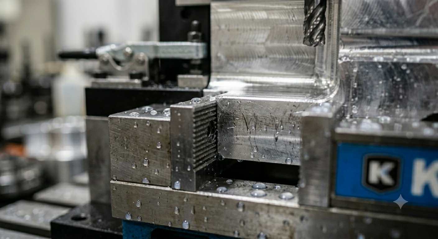
(AI generated) CNC vise securing a metal workpiece
A surprising number of machining problems start with CNC workholding, not the cutting itself.
A clamp that is too weak allows movement during cutting. A clamp that is too aggressive can distort the workpiece before machining even begins. Effective CNC clamping is therefore not simply about holding force. What matters is whether the part stays where it is supposed to stay once the tool engages, especially when cutting load starts to build and thin sections begin to react.
What Is CNC Clamping?
CNC clamping is the mechanical or pneumatic restraint of a workpiece against a fixture or machine table to prevent movement under cutting forces while maintaining the dimensional and geometric reference conditions the machining program assumes.
In practice, CNC clamping must accomplish several objectives at the same time. The workpiece must resist cutting forces, remain accessible to the cutting tool, avoid distortion under clamping pressure, and return to the same position every time the setup is repeated.
Common CNC Clamp Types and Fixture Solutions
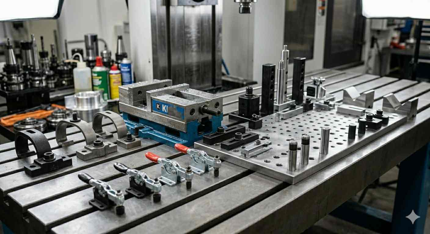
(AI generated) Various CNC clamping systems
Mechanical Clamps: Strap, Toe, and Edge Clamps
Strap clamps, toe clamps, and edge clamps remain the most common CNC clamps used in general machining operations.
Strap clamps are the most versatile and widely used CNC clamps in general machining. A strap bridges the workpiece surface, a stud through the table provides the clamping force, and the clamp step height adjusts to match the workpiece thickness. Their flexibility, low cost, and compatibility with standard machine tables make them one of the most widely used workholding solutions in CNC machining.
Toe clamps engage the edge of the workpiece rather than the top surface, which is the key advantage: the top face stays clear for machining. Side-acting toe clamps are the standard for operations where the entire top surface needs to be accessible. The limitation is that edge clamping generates horizontal force that can shift the workpiece laterally if the locating stops aren't positioned correctly to resist it.
Edge clamps in modular fixturing systems combine location and clamping in one element. They push the workpiece against a fixed stop while applying clamping force. Consistent, repeatable, and fast to set up once the system is established. The per-unit cost is higher than basic strap clamps but the setup time reduction justifies it at production volumes.
Vacuum Clamps
Vacuum clamping holds the workpiece through atmospheric pressure differential across a sealed contact area. Because there are no clamp bodies above the workpiece, vacuum fixtures provide excellent machining access. They are commonly used for flat parts that require large surface areas to remain unobstructed during machining.
Vacuum clamping works best on flat parts with sufficient sealing area. Holding force is limited by atmospheric pressure, so aggressive roughing operations or interrupted cuts often require mechanical support in addition to vacuum workholding.
Magnetic Clamps
Magnetic clamping generates holding force through the workpiece material itself. The fixture creates a magnetic field that the ferrous workpiece is attracted into. Since the holding force is generated through the material itself, magnetic workholding leaves most surfaces unobstructed and reduces fixture interference during machining. Setup is fast: place the part, activate the magnets, done.
The obvious limitation: ferrous materials only. Aluminum, titanium, copper, and most engineering plastics are non-magnetic and simply don't respond. For steel and cast iron parts on grinding machines and mills where surface accessibility is critical, magnetic chucks are standard equipment. For the broader range of materials in CNC machining, magnetic clamping is a specialized solution for ferrous-only applications.
Permanent magnetic chucks may require post-process demagnetization to remove residual magnetism before assembly or inspection. Electro-permanent magnetic chucks address this: the magnetic field is set by a brief electrical pulse, holds without continuous power, and releases with a reverse pulse. Safer and more controllable for production environments.
Hydraulic and Pneumatic Clamps
Hydraulic and pneumatic CNC clamping fixtures apply consistent, programmable clamping force through fluid pressure. The force is repeatable to within a few percent cycle to cycle, something that torque-wrench tightening of mechanical clamps genuinely isn't. For production environments where the same setup runs hundreds of times, this consistency matters for dimensional repeatability across the run.
Hydraulic clamps are typically selected when machining loads are high and fixture space is limited. They can generate substantial holding force from compact actuators, which is useful for large steel components and heavy roughing operations.
Pneumatic systems provide lower force but faster actuation. In automated production environments where loading time matters, pneumatic clamping is often preferred because it integrates easily with machine controls and shop air systems.
Hydraulic and pneumatic clamping fixtures are commonly used in production environments where repeatable clamping force is required.
Modular Fixture Systems
Modular CNC clamping fixtures use standardized grid plates, precision-located threaded holes, and a component library of clamps, stops, and supports that can be reconfigured for different parts without custom tooling. Many CNC fixture clamps are designed around modular fixturing systems because they allow rapid reconfiguration between jobs. The setup time advantage over custom fixtures is significant for low-to-medium volume work where a dedicated fixture would never pay back the fabrication cost.
The precision of modular systems depends largely on grid accuracy. High-quality modular systems can locate components within ±0.005-0.010 mm, which is adequate for most production work. For parts requiring better fixture repeatability, a dedicated fixture with tight locating pins and controlled reference surfaces is more appropriate than any modular system regardless of its precision grade.
Principles of Clamp Placement and Support
Supporting Cutting Forces Effectively
Clamps don't just hold the part down, they resist the vector of cutting forces. In face milling, the primary force is downward into the fixture, and any clamping arrangement that prevents the part from lifting works adequately. In side milling, the dominant force is horizontal, a clamp arrangement perfect for facing operations provides almost no resistance to the horizontal force component trying to push the part sideways.
Effective clamp placement locates restraint in opposition to the predominant force direction. If the operation generates horizontal force in the X direction, a stop or clamp that resists X-movement is what the setup needs, adding more vertical clamps doesn't address a horizontal force. Understanding the primary cutting force direction for the planned operations and placing workholding to resist it directly is the foundation of stable machining fixture design.
Avoiding Over-Constrained and Under-Constrained Setups
Under-constrained setups have degrees of freedom the cutting forces can exploit. The part rocks. It shifts. It vibrates. The machining program assumes a fixed workpiece and produces inconsistent results because the workpiece isn't fixed. This failure mode is obvious in retrospect but easy to miss during setup when the part feels solid under hand pressure.
Over-constrained setups are less obvious but equally problematic. Adding clamps beyond what's needed to stabilize the part doesn't improve rigidity, it introduces competing forces that stress the workpiece into a shape it wouldn't naturally hold. Release the clamps and the part springs back. On precision components, this clamp-induced distortion is the entire explanation for parts that measure correctly on the machine and incorrectly after release.
Using Support Points Strategically
Support points under the workpiece prevent downward deflection from both cutting and clamping forces. They're not locating elements, they don't position the part laterally, they prevent the workpiece from bending under load at unsupported spans. For large flat parts or thin structures, the support point positions determine whether the part remains flat during machining or develops a bow that gets locked in by the clamps.
The general principle: place supports as close as possible to the clamp application points, and directly under areas that will experience heavy cutting forces. A support point under a clamp converts the clamping force into a downward load on a rigid support rather than a bending moment across an unsupported span.
Applying the 3-2-1 Locating Principle
The 3-2-1 principle is the theoretical foundation of all fixture design. Three points define the primary plane, constraining three degrees of freedom (Z translation, X rotation, Y rotation). Two points on a perpendicular face define the secondary plane, constraining two more degrees of freedom (X translation, Z rotation). One point on a third face defines the tertiary datum, constraining the remaining translational degree of freedom (Y translation). Six constraints, six degrees of freedom, one fully located workpiece.
In practice, the three primary support points form the fixture's reference plane, typically the bottom face of the part sits on three support pads. The two secondary stops locate the part against one edge. The single tertiary stop locates against the adjacent edge. Clamps then hold the part against all six locating points
without introducing their own positioning influence. The logic is sound: any clamp that simultaneously acts as a locating element introduces positional variation with every cycle.
Real Shop Example
A thin-wall aluminum enclosure was clamped using standard strap clamps during rough milling.
After unclamping, dimensional inspection revealed a 0.18 mm wall deviation.
Replacing the setup with soft jaws and distributed support reduced deformation to less than 0.03 mm.
Cutting Force Interaction With Workholding
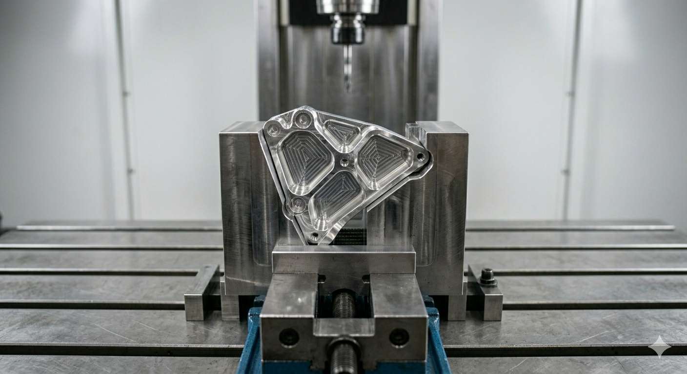
(AI generated) Complex thin-wall CNC component secured
Clamping Force vs Cutting Force Balance
The required clamping force to resist cutting isn't guesswork, it's calculable from the cutting parameters, material, and tool geometry.
Cutting force requirements vary significantly between materials. Stainless steel, titanium, and hardened alloys generally generate much higher cutting loads than aluminum, which often requires stronger workholding and more rigid fixture structures. A machining program that runs aggressive roughing passes on stainless steel with a clamping setup optimized for aluminum will move the part. The practical approach is to ensure clamping force exceeds the cutting force peak by a safety factor of 1.5-2.5, accounting for dynamic force variation during interrupted cuts.
Running through-spindle coolant at high pressure adds a force component that many setups do not account for. On small, lightweight, or vacuum-held parts, high-pressure coolant can contribute to workpiece movement if fixture rigidity is marginal.
Chatter Formation and Fixture Rigidity
Chatter is regenerative vibration, the cutting tool excites a frequency in the workpiece-fixture system, the tool cuts the resulting wavy surface on the next pass, the waviness excites more vibration. Once it starts, it feeds itself. The surface is destroyed and the tool takes damage.
Fixture rigidity is the primary control variable for chatter. A workpiece vibrating because the fixture is flexible responds to chatter excitation much more readily than a rigidly held workpiece. Adding damping mass, heavy fixtures, cast iron backing plates, fixture designs that don't have resonant frequencies in the cutting frequency range, reduces chatter susceptibility.
Increasing clamp force alone doesn't fix a structurally inadequate fixture, but a rigid fixture with appropriate clamping force is chatter-resistant across a wide range of cutting parameters.
Deformation in Thin-Wall Parts
Thin walls flex under cutting forces. The cutting tool engages, the wall deflects away, the tool removes less material than programmed. When the tool moves on, the wall springs back. The nominal dimension at that location is larger than intended, and the surface shows a convex error relative to the programmed path. This is deflection-induced dimensional error, and it's entirely predictable from the part geometry and cutting forces.
Workholding addresses this through support. Filling a thin-walled pocket with low-melting-point alloy or wax before machining the outer walls provides continuous support that prevents deflection. Machining from both sides alternately, small increments rather than full depth, keeps the wall balanced and minimizes net deflection at any point. These approaches require planning before the first cut, which is why they belong in the setup review rather than in the troubleshooting session after the first part fails.
Dynamic Stability in High-Speed Milling
At high spindle speeds, fixture dynamics become increasingly important. A setup that appears rigid under static loading can still vibrate if cutting frequencies coincide with the natural frequency of the workholding system. Increasing fixture rigidity and reducing unsupported spans are common methods for improving stability.
Resonance can occur when tooth engagement frequency approaches the natural frequency of the fixture-workpiece system, causing vibration even when static rigidity appears sufficient.
How to Choose CNC Clamps
Choosing CNC clamps usually starts with understanding what is most likely to compromise the setup.
For some parts, movement under cutting force is the primary concern. A rough-machined stainless steel component may remain stable only when the fixture provides sufficient rigidity and support close to the cutting zone. In these situations, the workholding system is expected to resist substantial machining loads throughout the operation.
Other parts create a different challenge. Thin-wall aluminum housings, electronic enclosures, and lightweight structural components often distort before they slip. Increasing clamp force may improve holding security while simultaneously reducing dimensional accuracy. Engineers frequently spend more time managing deformation than preventing movement.
Tool access also influences clamp selection. During five-axis machining or deep cavity milling, fixture components can restrict cutter movement long before holding force becomes a limitation. A setup that appears rigid on the machine table may still require redesign simply to provide access to critical features.
Production quantity eventually enters the discussion as well. A modular fixture may be entirely suitable for prototype work. Once volumes increase, setup efficiency becomes more important and dedicated workholding solutions become easier to justify.
The objective is not to maximize clamping force. The objective is to maintain a stable workpiece throughout machining while avoiding fixture-related problems that create unnecessary process variation.
Selecting Clamps for Different Part Types
| Workpiece Type | Main Clamping Challenge | Recommended Workholding Method | Key Consideration |
|---|---|---|---|
| Thin-Wall Components | Walls deflect under clamp pressure and spring back after machining, causing dimensional errors | Multiple low-force clamps, distributed clamping, vacuum fixtures | Spread force over a large area and avoid concentrated clamping loads |
| Large or Heavy Parts | Preventing deflection across long spans while supporting high mass | T-slot table clamping, strap clamps, step blocks, heavy-duty supports | Focus on support and rigidity rather than simply increasing clamp force |
| Irregular or Complex Geometries | Limited flat surfaces and inconsistent clamp contact points | Custom soft jaws, form-fitting nests, dedicated fixtures, vacuum fixtures | Match the fixture to the part geometry to improve stability and repeatability |
| Precision Components With Tight Tolerances | Clamp-induced distortion can exceed tolerance limits | Zero-point clamping systems, precision pull-stud systems, high-accuracy fixtures | Minimize setup variation and eliminate distortion as a source of dimensional error |
| High-Volume Production Parts | Maintaining repeatable positioning across many cycles | Dedicated production fixtures, hydraulic or pneumatic clamping systems | Prioritize repeatability, setup speed, and process consistency |
| Parts Requiring Multi-Side Machining | Repositioning can introduce alignment errors | 5-axis fixtures, tombstone fixtures, modular workholding systems | Maximize access while maintaining a single, repeatable datum reference |
| Soft Materials (Plastic, Aluminum, Composites) | Surface marking and deformation from clamp pressure | Soft jaws, vacuum fixtures, low-force clamping systems | Use only the minimum force necessary to resist cutting loads |
| Hard Materials (Steel, Cast Iron, Titanium) | High cutting forces require stronger restraint | Mechanical clamps, hydraulic fixtures, heavy-duty vises | Ensure clamping force exceeds machining loads without distorting the part |
Common CNC Clamping Mistakes and How to Avoid Them
| Common CNC Clamping Mistake | What Happens | Impact on Machining | How to Avoid It |
|---|---|---|---|
| Excessive Clamping Force | Applying more force than necessary to secure the workpiece. | Workpiece distortion, thin-wall deflection, stress concentration at clamp contact points, and possible permanent deformation in aluminum or plastic parts. | Use the minimum clamping force required to safely resist cutting loads. Calculate or validate holding force through testing rather than overtightening. |
| Poor Clamp Placement | Clamps are positioned far from the cutting zone. | Reduced stability, increased vibration, higher bending moments, and a greater likelihood of part movement during machining. | Position clamps as close as possible to the area where cutting forces are generated. Prioritize stability near the cut zone. |
| Insufficient Support Points | Workpiece is clamped but lacks adequate support underneath. | Part flexing, bowing, flatness errors, dimensional inaccuracies, and inconsistent surface finish. | Combine clamps with properly located support points. Ensure unsupported spans are minimized, especially for large or thin components. |
| Interference With Toolpaths | Clamp bodies obstruct cutter movement or machine travel. | Tool crashes, fixture damage, machine downtime, scrapped parts, and safety risks. | Verify fixture and clamp locations during CAM simulation. Model the complete setup and check clearances before production machining. |
Poor clamping can cause distortion, vibration, and costly scrap. At JLCCNC, our engineers evaluate fixturing and machining requirements before production to help ensure stable setups and consistent part quality.

Precision CNC Machining Service
Professional manufacturing, fast turnaround, and quality assurance.
Impact of Clamping on Machining Accuracy
Dimensional Accuracy
Every source of workpiece movement during machining is a source of dimensional error. Clamp-induced distortion, fixture repeatability between setups, and dynamic movement under cutting forces all contribute to dimensional scatter that appears in inspection results as process variation. Improving clamping consistency, zero-point systems, consistent torque application, standardized setups, reduces this variation directly. The parts don't get easier to machine; the setup variation that was contributing to dimensional scatter goes away.
Surface Finish
Vibration in the workpiece-fixture system shows up on the machined surface. Chatter marks, microtremors from inadequate clamping, and surface waves from resonant vibration are all workholding problems expressing themselves as surface finish problems.
Surface finish is influenced not only by cutting parameters but also by workholding stability. Insufficient fixture rigidity can introduce vibration into the machining process, producing chatter marks, waviness, or inconsistent surface texture even when cutting conditions appear appropriate.
Repeatability in Production
Production machining depends on the ability to reproduce the same workpiece position from one setup cycle to the next. Variations in clamp location, clamping force, or locating contact can introduce dimensional variation even when the machining program remains unchanged. This is the repeatability problem that production environments need to eliminate. Standardized CNC clamping fixtures with documented torque sequences, consistent support point positions, and verified locating contact reproduce the same workpiece position within the fixture cycle to cycle.
Without this standardization, dimensional variation is partly process variation and partly setup variation, and they're nearly impossible to separate without controlled experiments.
Clamp-Induced Deformation
A common inspection issue occurs when a part meets tolerance while clamped but moves outside specification after release due to elastic recovery. The explanation is almost always clamp-induced elastic distortion, the part held in a stressed state during machining, springs back when the clamps release.
This is particularly common with thin-walled aluminum parts clamped with excessive force, and with parts where the clamping geometry introduces bending moments that the part geometry can't resist without deflecting.
CNC Clamping Setup Optimization Checklist
| Optimization Step | Why It Matters | Best Practice |
|---|---|---|
| Plan Clamping Before Toolpath Generation | Prevents clamp-tool collisions and setup redesign later. | Design the fixture first, then create toolpaths around known clamp locations. |
| Minimize Clamp Relocation During Machining | Moving clamps can shift the part and introduce dimensional errors. | Complete each setup without repositioning clamps whenever possible. Use a separate operation if additional access is required. |
| Verify Tool Accessibility | Avoids crashes between tools, holders, and fixture components. | Dry-run the program and check clearance for both the cutting tool and toolholder before machining. |
| Inspect Setup Before Production | Catches alignment and workholding issues before scrap is created. | Verify datums, clamp direction, locating surface contact, and support point engagement before the first cut. |
Conclusion About CNC Clamping
Clamp selection alone rarely determines machining success. Placement, support strategy, part geometry, and cutting force direction often have a greater impact on stability than the clamp type itself.
Workholding limitations are usually identified during process planning rather than during machining. Parts with thin walls, limited access, or multiple setups often require fixture review before production begins.
JLCCNC evaluates fixturing and workholding requirements as part of manufacturing review to reduce setup-related risks before machining starts.
Upload your CAD file to receive a project-specific manufacturing review and quotation.
Precision CNC Machining Service
Professional manufacturing, fast turnaround, and quality assurance.
FAQ About CNC Clamping
Q: What is the difference between clamping and fixturing?
Fixturing locates and positions the workpiece, it defines where the part is in space relative to the machine. Clamping holds the part in that position against cutting forces. Both are required for accurate machining: a part that's located correctly but not clamped moves during cutting; a part that's clamped firmly without proper location produces accurate results in the wrong position.
Q: Which clamps are most suitable for thin-walled parts?
Distributed force clamps, wide strap clamps, vacuum clamping over large contact areas, or soft jaws that match the part contour, spread force over the maximum possible contact area to avoid local stress concentration that thin walls can't resist. Vacuum clamping is often the best solution for flat thin-walled parts because it applies holding force uniformly across the contact face without the point loads that mechanical clamps generate.
Q: Can magnetic clamps be used on all materials?
No. Magnetic clamping works only on ferromagnetic materials, steel and cast iron primarily. Aluminum, titanium, copper, brass, and most engineering plastics are non-magnetic and don't respond to magnetic workholding systems. For ferrous parts in grinding and milling operations, magnetic chucks are excellent. For non-ferrous materials, mechanical, vacuum, or hydraulic clamping is required.
Q: How do clamping forces affect surface finish?
Insufficient clamping allows workpiece movement and vibration that appear as surface irregularities. Excessive clamping distorts the part, and the distorted geometry produces surfaces that don't match the programmed form after release. Correct clamping, sufficient to resist cutting forces with a safety factor, distributed to avoid local distortion, produces the surface finish that the cutting parameters are capable of delivering.
Q: How are clamps positioned for irregular geometries?
Soft jaws machined to match the part contour, form-fitting nest fixtures, and adjustable support systems that accommodate non-planar surfaces are the standard approaches. The goal is maximum contact area distributed around the part perimeter, with supports under any section that cutting forces will load. For production volumes, custom fixtures with contoured contact surfaces provide better repeatability than adjustable solutions configured differently each cycle.
Q: What are common mistakes in CNC clamping?
Placing clamps far from the cutting zone. Using excessive force on thin-walled parts. Neglecting support points between clamp locations. Not checking clamp clearance against the toolpath before the first cut. Repositioning clamps mid-operation without re-indicating the part. And the most common one: designing the fixture after the toolpath instead of before.
Q: What is the 3-2-1 locating principle in CNC fixturing?
Three points define the primary plane, usually the bottom face, constraining three degrees of freedom. Two points on a secondary face constrain two more. One point on a third face constrains the final translational degree of freedom. Six points, six degrees of freedom, fully located part. Clamps then hold the part against all six locating points. Any setup that uses fewer than six constraints leaves degrees of freedom for cutting forces to exploit. In rigid fixture designs, applying more constraints than necessary can over-constrain the workpiece and increase the risk of distortion.
Q: How does clamping affect tool deflection in milling?
Indirectly but significantly. A rigidly held workpiece resists the cutting forces that would otherwise deflect the tool away from the programmed path. Workpiece movement under cutting forces appears identical to tool deflection in the resulting part, both produce surfaces that deviate from the programmed geometry. Improved workholding reduces workpiece movement that may otherwise be mistaken for tool deflection in the finished part.
Popular Articles
• Cutting with Precision: A Comprehensive Guide to CNC Water Jet Technology
• CNC Coolant Explained: Types, Maintenance & Safety
• Rake Angle in Machining: Machinists’ Guide to Perfect Cuts
• What Steps Are Taken To Minimize Waste In CNC Machining Processes?
• How EDM Wire Cutting Works: Complete Guide to Precision CNC Wire Cutting
Keep Learning
Chatter in Machining: Causes, Effects, and How to Reduce It
CNC milling operation producing visible chatter marks on an aluminum workpiece Quick Chatter Diagnosis Checklist Symptom Most Likely Cause First Action High-pitched squeal Regenerative chatter Change spindle speed ±15% Chatter only in deep pockets Excessive tool overhang Shorten tool Chatter on thin walls Low workpiece rigidity Improve fixturing Chatter after tool replacement Runout / holder issue Check tool holder Chatter only during finishing DOC too small / rubbing Increase feed or adjust speed It ......
What Is Tool Offset in CNC? Types, Setup & Best Practices
CNC tool offset setup with measurement overlay Key Takeaways CNC offsets connect programmed intent with actual cutter position. Length data guides Z-axis depth control. Radius data protects part size during contour milling. Geometry values define the cutter's measured baseline. Wear values support fine correction during production. Verified data lowers scrap risk before full machining. Good offset habits protect tools, fixtures, and parts. In the context of CNC machining , tool offset is the quiet set......
Trochoidal Milling: Complete Guide to High-Efficiency CNC Machining
Key Takeaways Trochoidal milling combines circular cutter motion with continuous forward feed. The cutter normally engages 5 to 20% of its diameter instead of making a full-width cut. A smaller engagement angle limits force changes during slotting and pocket roughing. Low radial engagement often allows greater axial depths of cut than conventional slot milling. CAM software calculates the circular path automatically from the selected machining parameters. This strategy is widely applied to titanium, s......
What Is Die Casting? Process, Materials, and Applications
Key Takeaways Die casting is a metal casting process that forces molten metal into a reusable steel mold under high pressure, producing parts with tight tolerances and good surface finish at high volume. Aluminum die casting is the most common form by far, thanks to its combination of light weight, decent strength, and good corrosion resistance. The die casting process runs through mold preparation, injection, cooling, and ejection in a cycle that can repeat every few seconds to minutes depending on p......
First Angle vs Third Angle: Understanding Orthographic Projection Methods
Key Takeaways Orthographic projection is the system that lets a 3D part be represented through multiple 2D views, front, top, side, and so on. First angle projection and third angle projection are the two standard methods for arranging those views, and they place views in opposite positions relative to the object. First angle projection is the ISO standard used across most of Europe, India, China, Russia, and many other countries following ISO standards Third angle projection is the standard in the Un......
Micro EDM Machining: Capabilities, Materials, and Applications for Precision Components
Key Takeaways About Micro EDM Machining Only electrically conductive materials can be machined. Hole diameters can reach below 50 μm on specialized equipment. The process produces almost no mechanical cutting force, making it suitable for thin or delicate features. Surface integrity still requires attention because recast layers and heat-affected zones may remain after machining. Micro EDM is often combined with CNC machining, with milling producing the main geometry before EDM finishes critical micro......