What Is a CNC Controller? Types, Software & How CNC Controllers Work
29 min
- What Is a CNC Controller
- How CNC Controllers Work
- CNC Motion Control and Servo Systems
- CNC Controller vs Motion Controller vs PLC
- CNC Controller Hardware Architecture
- CNC Control Software and Programming System
- Types of CNC Controller Systems
- Applications of CNC Controllers in Industrial Manufacturing
- Choosing the Right CNC Controller for Your Machine
- FAQs about the CNC Controller
Key Takaways
• The controller strongly influences achievable positioning accuracy, contouring performance, and repeatability, but actual machine accuracy also depends on the mechanical structure, feedback devices, thermal stability, servo tuning, and machine condition.
• Different types of CNC controllers suit different applications, open-loop stepper-based systems for light-duty work, closed-loop servo systems for production precision machining.
• Major CNC controller platforms include FANUC, Siemens, Mitsubishi, Heidenhain, and Haas, each with different strengths in capability, programming environment, and integration. The controller is not interchangeable with the machine, controller capability caps what the machine can achieve regardless of mechanical quality.
A CNC controller is the hardware and software system that reads G-code, calculates tool motion, and sends real-time commands to the machine’s axes, spindle, and auxiliary systems. It acts as the brain of a CNC machine, coordinating motion, feedback, and machine logic to produce accurate parts.
Get the controller right and the machine performs to its specification. Get it wrong, or misunderstand what it's doing, and no amount of fixturing or tooling selection fixes the problem.
This guide covers how CNC machine controllers actually work, what differentiates them, and what matters when specifying or working with one.
What Is a CNC Controller
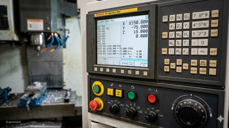
(AI generated) FANUC CNC controller front panel showing a running G-code program
Definition of a CNC Controller
A CNC controller is the hardware and software system that reads machining programs, performs real-time interpolation calculations, and outputs coordinated command signals to the machine's drive systems to produce controlled tool movement relative to the workpiece.
That definition is accurate but incomplete without context. The CNC machine controller isn't just a computer running G-code. It's a real-time control system that has to calculate axis positions, velocities, and accelerations continuously, typically at update rates of 1,000 to 4,000 times per second, depending on the controller architecture, interpolation and servo-related update cycles may run in the sub-millisecond to several-millisecond range. While simultaneously monitoring feedback from encoders, managing I/O signals for coolant and tool changers, enforcing software travel limits, and maintaining interpolation accuracy across multiple axes moving simultaneously at different speeds.
A standard PC without real-time extensions is suitable for programming and simulation, but production-grade motion control requires deterministic real-time behavior delivered through dedicated motion hardware, FPGA-based I/O, or a real-time operating environment.
Role in CNC Machines
The CNC controller sits at the center of everything the machine does. On one side it receives the machining program, either loaded directly or transferred from CAM through DNC. On the other side it outputs command signals to servo amplifiers driving the axis motors, spindle drive, coolant system, tool changer, and every other controlled element of the machine.
On a 3-axis machining center, this happens across X, Y, and Z simultaneously. On a 5-axis machine, the CNC motion controller coordinates two rotary axes alongside three linear axes, calculating the complex kinematic transformations needed to keep the tool vector correct at every point along the toolpath. The computational demand scales significantly with axis count, which is part of why 5-axis capable controllers are substantially more expensive than 3-axis equivalents.
Why CNC Controllers Are Important
Two machines with similar castings and spindle power can behave very differently once feed rates rise. In many cases, the difference comes from the controller's motion planning and servo response rather than the mechanics alone. A mechanically excellent machine with a limited CNC controller performs below its mechanical potential. A capable controller on a well-built machine delivers the accuracy, surface finish, and cycle time that the machine was designed for.
Specifically, the controller determines positioning accuracy through the quality of its interpolation and servo loop closure. It determines surface finish through look-ahead capability, how many blocks ahead it reads to smooth velocity transitions before reaching a direction change. It determines cycle time through feed rate ceiling and acceleration/deceleration management. And it determines integration capability through communication protocols, data logging, and whether the machine can participate in a connected CNC automation system.
At JLCCNC, controller specification is part of machine selection, not an afterthought. Running precision automotive and aerospace components on 500+ machine tools means controller capability directly affects whether parts hold tolerance across a full production run or drift at the edges of the specification. A controller that loses interpolation accuracy at high feed rates, or that can't communicate reliably with the MES, creates problems that no amount of operator skill compensates for.

Precision CNC Machining Service
Professional manufacturing, fast turnaround, and quality assurance.
How CNC Controllers Work
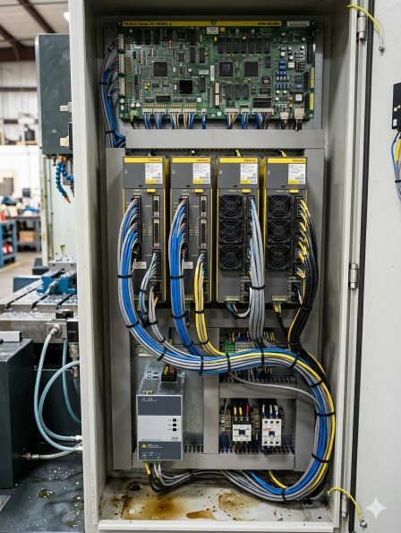
(AI generated) Open CNC machine electrical cabinet
Input and Command Processing
That interpretation step matters more than most people realize. The controller isn't just reading coordinates and moving motors. It's calculating feed rates, ramping acceleration and deceleration smoothly so the machine doesn't jerk, managing tool radius compensation so the programmed path produces the correct part geometry, and handling modal states, remembering that G41 is still active three blocks after it was called, for example.
Modern CNC controller software adds another layer: look-ahead processing. Rather than executing one block and then reading the next, the controller reads 50-200 blocks ahead simultaneously, pre-calculating the velocity profile for the upcoming toolpath so it can maintain constant feed rate through direction changes without slowing to a stop. On complex surface programs with thousands of short blocks, look-ahead is the difference between a smooth machined surface and one that shows every block boundary as a small facet.
The human interface, the screen, keyboard, and handwheels on the machine front panel, is also part of the input system. Operators use this to load programs, set tool offsets, jog axes manually, and monitor what the machine is doing in real time.
On modern controllers like FANUC 0i Siemens 840D, or Heidenhain TNC 640, that interface is sophisticated enough to display 3D toolpath simulation, real-time load graphs, and production statistics.
G-code Interpreter and Execution Engine
G-code is the language CNC machines speak. The interpreter is what reads it.
Every line of a G-code program, every G01, every X coordinate, every F feed rate, passes through the interpreter before anything moves. The interpreter parses each block, checks for syntax errors, resolves any calculated expressions, applies active modal states, and converts the result into a motion command the execution engine can act on.
The execution engine takes those commands and actually runs them, managing feed rate profiles, triggering M-code functions like coolant on/off and tool changes, handling program flow like subroutine calls and loops, and passing position targets to the motion control system.
For a full breakdown of G-code and M-code commands and how they work together in a machining program, read our G-code and M-code guide.
Toolpath Execution System
The toolpath execution system is the layer between the G-code interpreter and the motion controller. It takes the sequence of motion commands from the interpreter and turns them into a continuous, smooth machine path.
Tool radius compensation (G41/G42) lives here. When the programmer specifies the tool centerline should be offset from the programmed path by the tool radius, the execution system recalculates every move in real time to shift the path by the correct amount in the correct direction. Change the tool radius offset value and the same program cuts a slightly larger or smaller part, which is how machinists trim dimensions without editing the program.
Tool length compensation (G43/G44) offsets the programmed Z position by the measured tool length, so the program can be written to part coordinates regardless of how long the actual tool is. The execution system applies this offset transparently to every Z move in the program.
Cutter compensation calculations have to handle geometry edge cases, inside corners where the offset path would self-intersect, outside corners where a transition arc needs to be inserted, changes in compensation direction mid-program. Handling these correctly without producing gouges or air cuts is one of the more mathematically involved parts of CNC controller software, and the quality of the implementation shows up directly in part accuracy on complex contoured geometry.
Motion and Axis Control
The motion control section of the CNC controller takes the interpreted commands and turns them into actual electrical signals driving the machine's servo motors. This is where the abstract numbers in a G-code program become physical movement.
Axis interpolation is how the controller coordinates multiple axes simultaneously to produce the programmed path. Moving from X10 Y0 to X10 Y10 is simple, one axis moves, one stays. Moving from X10 Y0 to X17.32 Y15.0 along a diagonal requires both axes moving at precisely coordinated rates so the tool follows a straight line rather than a staircase. The CNC motion controller handles this coordination continuously, recalculating position commands for every axis many times per millisecond.
Feed rate override, rapid traverse limits, and axis-specific acceleration and deceleration limits are all managed in this section. When you turn the feed override knob on the front panel, you're telling the motion control system to scale the velocity profile up or down in real time without affecting the programmed path geometry.
How Motion Control Works in CNC Systems
CNC motion control is a continuous closed-loop process running at update rates of 1-4 milliseconds per cycle on most modern controllers. Every cycle, the controller calculates where each axis should be, compares that to where each axis actually is, and generates a correction signal if there's a difference.
The speed of this loop determines how accurately the machine follows the programmed path at high feed rates. A controller updating position commands every 4ms at a feed rate of 10,000 mm/min moves the tool 0.67mm between updates, coarse enough to matter on tight radii at high speed. High-end controllers running 0.5ms or 1ms cycles maintain much finer path control at aggressive feed rates, which is why machine and controller selection matters for high-speed machining applications specifically.
Machine Communication Systems
The controller doesn't just talk to servo drives. It talks to everything, the spindle drive, the tool changer, coolant solenoids, door interlocks, probing systems, pallet changers, and any peripheral equipment connected to the machine.
This communication happens through two main channels. The PLC, Programmable Logic Controller, embedded within the CNC controller handles machine logic: sequencing tool changes, managing coolant on/off based on program commands, monitoring safety interlocks, and responding to operator inputs from the front panel. The PLC runs its own ladder logic program independently of the part program, handling the machine's discrete I/O while the CNC handles the motion.
The external communication side handles connections to factory systems. Modern CNC controllers support OPC-UA, MTConnect, FOCAS (on FANUC systems), and other protocols that allow MES and monitoring software to read machine state, production counts, alarm history, and spindle load data in real time. This is the connection that makes CNC automation systems and factory-wide monitoring possible, without it, each machine is an island.
CNC Motion Control and Servo Systems
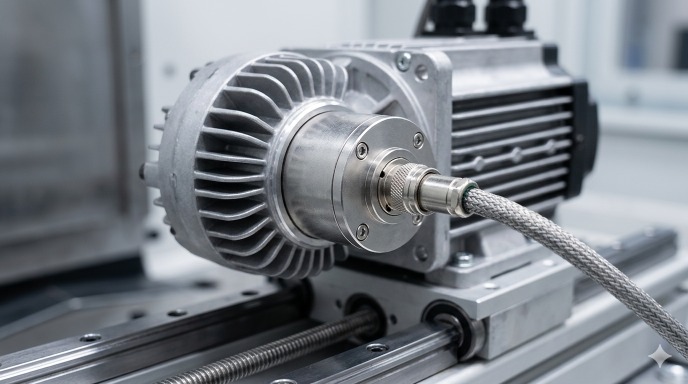
(AI generated) Rotary encoder mounted on the rear shaft of a CNC servo motor
Interpolation: Linear, Circular, Helical Motion
Interpolation is how the CNC motion controller produces smooth toolpaths from simple coordinate commands.
Linear interpolation (G01) moves the tool in a straight line from current position to the commanded endpoint, coordinating all active axes simultaneously at the programmed feed rate. Simple in concept, but the mathematics runs continuously for every millisecond of motion.
Circular interpolation (G02/G03) generates circular arcs from a center point, radius, and endpoint. The controller calculates the continuous position updates required to maintain a circular path, both X and Y axes must follow sinusoidal position profiles perfectly synchronized, or the resulting arc is elliptical rather than round. The roundness error produced by circular interpolation at high feed rates is a direct measure of the controller's motion control quality.
Helical interpolation combines circular motion in two axes with simultaneous linear motion in a third, the tool follows a helix. This is how thread milling and helical ramp entries work. The controller coordinates three axes simultaneously to maintain the programmed helix geometry throughout the move.
Servo Motor Feedback Loop
The servo feedback loop is what makes CNC positioning repeatable. Without it, the controller would be issuing commands with no knowledge of whether the machine actually executed them correctly.
A linear or rotary encoder mounted on each axis measures actual position and sends that data back to the controller thousands of times per second. The controller compares commanded position to actual position, calculates the error, and adjusts the drive signal to the servo motor to reduce it. This loop runs continuously throughout every move.
Encoder resolution determines the smallest position increment the feedback system can detect. Modern linear encoders on precision machining centers resolve to 0.001mm or finer (1 micron) which is why the controller can maintain positioning accuracy at that level if the mechanical system supports it. Rotary encoders on the motor itself are less accurate because they don't account for ballscrew backlash and pitch error between the motor and the axis. Direct linear scales on the machine slides eliminate those mechanical errors from the feedback path entirely, which is why high-precision machining centers use linear scales rather than motor-mounted encoders.
The gain settings of the servo feedback loop, how aggressively the controller responds to position error, are tuned during machine commissioning. High gain produces fast error correction but can cause oscillation and vibration. Low gain produces smooth motion but allows larger following errors at speed. On a well-built and properly tuned machine, following error during normal cutting can be kept very small, often within a few microns, depending on axis design, feedback system, and operating conditions.
Positioning Accuracy and Error Correction
The positioning accuracy of a CNC machine is not just a property of the servo system. It's a combination of servo performance, mechanical condition, thermal stability, and the error compensation built into the CNC controller software.
Pitch error compensation corrects for known inaccuracies in the ballscrew pitch along each axis. The ballscrew is never perfectly uniform, there are small pitch errors at various positions that cause the actual axis position to deviate from the commanded position even when the servo system is working perfectly. The controller stores a compensation table measured during machine calibration and applies corrections in real time as the axis moves through each position.
Backlash compensation corrects for the small amount of play between the ballscrew nut and screw that causes the axis to not immediately move when direction reverses. The controller adds a preset compensation move when direction reversal is detected, eliminating most of the backlash error from the part program's perspective.
Thermal compensation is the most sophisticated error correction in modern CNC controller software. As the machine warms up during a production shift, the ballscrews and structural components expand thermally, shifting axis zero points and changing effective pitch. Controllers with thermal compensation use temperature sensors at multiple locations on the machine and apply real-time corrections to axis positions based on measured thermal expansion. On a machine running a long production shift, thermal compensation can maintain positioning accuracy within 0.005mm across a full shift where an uncompensated machine might drift 0.02-0.05mm from morning to afternoon.
CNC Controller vs Motion Controller vs PLC
The three systems are related, but they solve different control problems.
| Factor | CNC Controller | Motion Controller | PLC |
|---|---|---|---|
| Primary job | Runs the full machining operation, reads G-code, controls axes, manages the machine | Controls coordinated multi-axis motion in automated systems | Controls machine logic, sequences, interlocks, I/O |
| What it processes | G-code programs, tool offsets, compensation tables | Position commands, velocity profiles, encoder feedback | Discrete inputs and outputs, ladder logic, timing |
| Typical hardware | Dedicated machine control unit with operator interface | Standalone card or module in a motion system | Dedicated PLC unit or embedded within CNC controller |
| Programming language | G-code, M-code, manufacturer-specific cycles | Manufacturer motion language, IEC 61131 | Ladder logic, function block diagram, structured text |
| Feedback system | Full closed-loop with encoder, thermal, pitch error compensation | Closed-loop servo control | Typically open-loop or simple on/off sensing |
| Where it lives | On the CNC machine itself | In robotics, automation cells, multi-axis systems | Embedded in the CNC controller or as a standalone unit |
| Interpolation | Yes, linear, circular, helical, spline | Yes, often simpler, application-specific | No |
| Operator interface | Full screen, keyboard, handwheels, simulation | Minimal, usually no dedicated HMI | Basic or none, usually monitored through SCADA or HMI |
| Typical brands | FANUC, Siemens, Heidenhain, Mitsubishi, Mazak | Galil, Aerotech, Parker, Beckhoff | Siemens S7, Allen Bradley, Mitsubishi FX, Omron |
| Used when | Running a CNC machine tool | Coordinating motion in automation outside a machine tool | Managing machine sequences, safety, and peripheral control |
| Can it replace the others | Partially, modern CNC controllers have embedded PLC | No, needs surrounding system to be useful | No, no toolpath or G-code capability |
| Cost range | $5,000–$50,000+ | $500–$10,000 | $200–$5,000 |
When each system is used in plain terms: A CNC controller runs the machine. A motion controller coordinates movement in systems like robots, gantries, and automation cells that don't need full G-code capability. A PLC manages the logic around the machine, door interlocks, coolant sequencing, alarm handling, conveyor control.In many modern machine tools, CNC, PLC, and motion-control functions coexist within one integrated control architecture, even if they are not exposed as separate physical units.
CNC Controller Hardware Architecture
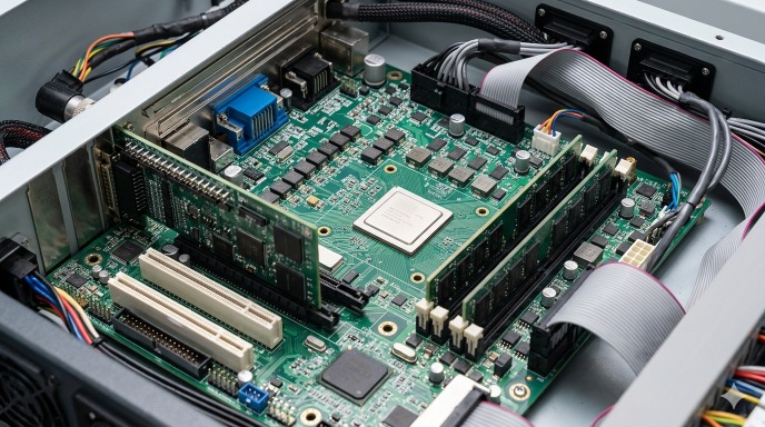
(AI generated) Industrial PC based CNC control motherboard showing FPGA chip
Embedded CNC Controllers
Most CNC machines you'll encounter in production, FANUC, Siemens, Heidenhain, Mitsubishi, run on embedded controllers. These are purpose-built hardware units designed from the ground up to control machine tools and nothing else.
The entire system lives in a sealed industrial unit mounted in the machine cabinet. The processor, memory, I/O interfaces, servo drive communication, and operator interface all come from the same manufacturer, designed to work together. That's the main advantage, reliability. There's no compatibility uncertainty, no driver conflicts, no general-purpose operating system getting in the way. A FANUC 0iMF controller on a machining center will run the same way on day one and year ten.
The downside is flexibility. Embedded controllers are closed systems. You can configure them within the parameters the manufacturer allows, but you can't fundamentally change how they work or add capabilities the manufacturer didn't design in. For standard production machining, that's fine. For highly customized automation or research applications, it becomes a limitation.
Embedded controllers also handle their own real-time requirements internally, the motion control loop running every 0.5-4ms happens on dedicated hardware that guarantees timing regardless of what else the system is doing. That determinism is critical for accurate motion control and is difficult to achieve on general-purpose computing hardware.
PC-Based CNC Control Systems
PC-based CNC control uses standard industrial PC hardware running specialized CNC controller software on top of a real-time operating system. The machine axes connect to the PC through motion control cards or EtherCAT servo drives, and the CNC software handles all the functions a dedicated embedded controller would.
Siemens Sinumerik ONE uses an industrial PC-based architecture while retaining the structure and performance expectations of a high-end industrial CNC platform.
The appeal is openness. A PC-based CNC system can run standard software alongside the CNC, custom HMI applications, data logging, direct database connections, vision system integration, without the restrictions of a closed embedded platform. Modifying behavior, adding custom cycles, and integrating third-party software is significantly easier.
The challenge is real-time performance. A standard Windows or Linux operating system handles tasks in priority order but can't guarantee exactly when any specific task will run. CNC motion control needs guaranteed timing, the servo loop must update every millisecond without exception. PC-based systems solve this with real-time OS extensions (like Beckhoff's TwinCAT real-time kernel running below Windows) that isolate motion control from the general-purpose computing load. When implemented correctly, modern PC-based systems match embedded controllers on motion performance. When implemented poorly, the results show up as surface finish problems and following errors.
Industrial CNC Control Boards
Between full embedded controllers and PC-based systems sits a category of industrial CNC control boards, dedicated hardware designed to provide CNC motion control capability without the full package of an embedded controller.
Mesa Electronics FPGA cards, Vital Systems DSPMC, and similar products provide the motion control hardware, encoder interfaces, step/direction outputs, analog command outputs, while the CNC software runs on a connected PC. LinuxCNC is the most common open-source CNC controller software used with these boards, running on a real-time Linux kernel that handles the motion control loop.
This architecture is common in custom machine builds, retrofits of older machines, and research applications where the flexibility of open-source CNC controller software outweighs the support advantages of commercial systems. A hobbyist building a CNC router, a university lab building a custom research machine, or a small shop retrofitting a 1980s knee mill with modern control, these are the typical users of industrial control board architectures.
The trade-off is support and development time. Commercial embedded controllers come with manufacturer support, established workflows, and decades of production-proven reliability. Open-source PC-based systems require more technical investment to set up, tune, and maintain, but give complete control over every aspect of how the controller behaves.
FPGA-Based Motion Control Systems
FPGA stands for Field Programmable Gate Array, a chip that can be configured to perform specific logic functions in hardware rather than software. In CNC motion control, FPGAs are used to handle the fastest, most timing-critical parts of the control loop at the hardware level.
The reason FPGAs matter in motion control is determinism. A microprocessor running software handles one instruction at a time, in sequence. An FPGA handles multiple operations genuinely simultaneously in dedicated hardware logic, with no operating system overhead and guaranteed nanosecond-level timing. For encoder counting, step pulse generation, and real-time position error calculation, that timing precision matters.
In high-end embedded CNC controllers, FPGAs handle the low-level motion control hardware while the main processor handles G-code interpretation, user interface, and higher-level functions. The FPGA is what lets a modern FANUC or Heidenhain controller maintain a 0.5ms servo update rate reliably without any variation.
In open-source systems like LinuxCNC with Mesa hardware, the Mesa FPGA card handles all the real-time I/O, encoder reading, step generation, analog outputs, while LinuxCNC running on the PC handles everything else. This division of labor between the FPGA and the PC processor is what makes a $200 Mesa card capable of motion control performance that would otherwise require expensive dedicated hardware.
The practical implication for anyone specifying or evaluating CNC controller systems: FPGA-based motion control in the hardware architecture is a sign that the system takes real-time performance seriously. It's not a marketing term, it's a specific hardware choice that has measurable effects on servo loop timing, following error, and ultimately on surface finish and positional accuracy at high feed rates.
CNC Control Software and Programming System
Real-Time Machine Monitoring
Modern CNC controllers monitor the machine continuously during operation, not just to detect faults but to track performance and catch developing problems before they produce scrap.
Spindle load monitoring watches the current draw on the spindle motor and reports it as a percentage of rated load. A sharp tool cutting aluminum at correct parameters might load the spindle at 20-30%. A worn tool or incorrect feed rate pushes that toward 80-100%. Some controllers can trigger automatic feed rate reduction or tool change when spindle load exceeds a threshold, useful in unattended automation where nobody is watching the machine.
Servo load monitoring does the same for each axis drive. Abnormally high axis load on a move that should be light can indicate a mechanical problem, worn linear guides, a contaminated ballscrew, a workholding issue causing the part to shift during cutting.
Thermal monitoring tracks temperature at spindle bearings, servo drives, and in some machines at ballscrew locations. Temperature data feeds into the controller's thermal compensation system as discussed in the motion control section, and it also triggers alarms if temperatures exceed safe limits.
In networked production environments, all of this monitoring data streams to MES and factory monitoring platforms in real time. The CNC controller software is the source of that data, the quality and completeness of what the controller reports determines how useful the factory-level monitoring actually is.
CAM Integration with CNC Controller
The connection between CAM software and the CNC controller used to be simple: CAM generates G-code, operator loads G-code onto machine, machine runs it. That workflow still exists and works fine for most applications.
For automated production environments and complex high-speed machining, the integration has gotten more sophisticated. Direct NC file transfer from CAM systems to machine controllers over the factory network, rather than USB sticks or manual transfers, reduces setup time and eliminates the transcription errors that come with manual file management. Program verification on the controller before the first cut, using the controller's own simulation rather than the CAM simulation, catches any post-processor issues that might not show up until the program runs on the actual machine.
Some CAM systems now generate controller-specific optimized code rather than generic G-code, using FANUC's high-speed machining cycle parameters, Siemens CYCLE800 for tilted plane operations, or Heidenhain's FK conversational programming for specific operations. These controller-native features often produce better results than equivalent generic G-code because they're designed to work with the controller's internal motion planning rather than around it.
Types of CNC Controller Systems
Open-Loop CNC Controllers
Open-loop control means the controller sends commands to the motors and assumes they were executed correctly. There's no position feedback, no encoder reporting where the axis actually ended up. The controller trusts the motor to move exactly as commanded.
In practice, open-loop CNC systems use stepper motors. A stepper motor moves in discrete steps, typically 200 steps per revolution, and each step is a fixed angular increment. Send the motor 200 pulses and it rotates exactly one revolution, in theory. Send it 20,000 pulses at the right pitch ballscrew and the axis moves exactly 100mm, in theory.
The problem is that stepper motors can miss steps under load. If the cutting force exceeds what the motor can handle at the commanded speed, the motor doesn't move as far as commanded but the controller doesn't know, it has no feedback. The axis position drifts from what the controller thinks it is. Parts come out wrong and the controller has no way to detect it.
Open-loop systems are cheap and simple. They show up in hobby CNC routers, plasma cutters, vinyl cutters, and low-cost entry-level machines where absolute positioning accuracy below 0.1mm isn't required and cutting forces are low enough that missed steps are unlikely. They are generally unsuitable for precision production machining where tight tolerances, higher cutting forces, and process reliability are critical.
Closed-Loop CNC Controllers
Closed-loop control adds position feedback to the system. An encoder on the motor or directly on the machine axis measures actual position and reports it back to the controller continuously. The controller compares commanded position to actual position and corrects any difference in real time.
This is how every serious CNC machine tool operates. Servo motors with encoders replace stepper motors. The controller knows exactly where each axis is at all times, can detect and correct following error, and can alarm out if the axis fails to reach the commanded position within a defined tolerance, rather than silently producing wrong parts.
The performance of a closed-loop CNC system depends on the quality of the feedback device, the servo loop update rate, and the tuning of the control algorithm. A well-tuned closed-loop system on a rigid machine maintains positioning accuracy within 0.002-0.005mm during normal cutting operations. A poorly tuned system on the same hardware produces following errors that show up as surface finish problems and dimensional scatter.
Closed-loop control also enables the error compensation features discussed earlier, pitch error compensation, thermal compensation, and backlash compensation all depend on having accurate position feedback to work against. Open-loop systems can't implement any of these because they have no reliable knowledge of actual axis position.
Applications of CNC Controllers in Industrial Manufacturing
| Application | Controller Requirement | Typical Controller | Key Capability Used |
|---|---|---|---|
| High-precision milling | Sub-micron positioning, thermal compensation, high look-ahead block processing | Heidenhain TNC 640, Siemens 840D | Linear scale feedback, pitch error compensation, 500+ block look-ahead |
| Multi-axis machining centers | 5-axis simultaneous interpolation, RTCP (rotary tool center point), tilted plane cycles | FANUC 30i, Siemens 840D sl | Coordinated 5-axis motion, tool vector control, dynamic feed rate management |
| CNC turning and lathe systems | C-axis coordination, live tooling synchronization, thread cutting cycles | FANUC 0i-TF, Mazatrol, Mitsubishi M800 | Spindle-axis synchronization, G76 threading, polygon turning |
| Robotics integrated CNC | Robot-CNC handshake signals, coordinated motion between machine and robot, cell controller communication | FANUC 0i with PMC integration, Siemens 840D with ROBX | PLC I/O coordination, program transfer triggers, OPC-UA data output |
Choosing the Right CNC Controller for Your Machine
Compatibility Considerations
Start with the machine, not the controller. The controller has to match the machine's servo drives, encoder types, I/O count, and spindle interface, and these aren't interchangeable across brands without significant engineering work.
If you're buying a new machine the controller is usually chosen by the builder. Your job is to specify requirements, number of axes, required I/O for peripherals, communication protocols needed for factory integration, and verify the proposed controller meets them before the order is placed.
If you're retrofitting an older machine, compatibility cuts both ways. The new CNC controller software needs to support the machine's servo drives, or the drives need to be replaced too. Replacing drives means re-tuning the entire servo system. Budget for it rather than assuming the controller drops in cleanly.
Tooling systems, probing, and any automation peripherals connected to the machine all need compatible interfaces on the controller. A tool presetter communicating over RS-232 won't talk to a controller that only has Ethernet interfaces without an adapter, small details that create project delays when discovered late.
Performance and Precision Requirements
Match controller capability to what the application actually needs, not to what sounds impressive in a spec sheet.
For general production machining to ±0.02mm, brackets, housings, structural components, a mid-range embedded controller handles the work reliably. FANUC 0i series, Siemens 828D, Mitsubishi M70, all capable, well-supported, and cost-appropriate.
For precision work to ±0.005mm and below, tooling, gauging, medical components, optical mounts, the controller needs linear scale feedback rather than motor encoders, thermal compensation, and a servo loop update rate of 1ms or faster. Heidenhain TNC 640, Siemens 840D, FANUC 31i, these are the systems that maintain that accuracy level reliably in production.
For high-speed machining of complex surfaces, mold and die, aerospace contoured parts, look-ahead block processing depth and the quality of the velocity planning algorithm determine surface finish as much as the machine's mechanical condition. Specify minimum look-ahead depth of 200+ blocks and verify the controller handles short-block programs without velocity fluctuation.
Software and Integration Factors
A controller that can't connect to your factory systems creates an island of data that nobody can use. Before selecting a CNC controller, confirm it supports the communication protocols your MES or monitoring platform requires, OPC-UA is the current standard, MTConnect is common on older installations, FANUC FOCAS is required for FANUC-specific integrations.
CAM post-processor availability matters more than most people account for. Every major CAM platform has proven post-processors for FANUC, Siemens, and Heidenhain. Less common controllers may require custom post development, adding cost and time before the first part runs.
Operator familiarity is a real factor in production environments. Retraining machinists on a new controller interface takes time and produces errors during the transition. If your floor runs FANUC, switching to Siemens for one machine creates a two-system environment that complicates training, maintenance, and spare parts. Standardizing on one controller platform across a facility has operational value that justifies paying a slight premium for the standardized option.
FAQs about the CNC Controller
Q: What does a CNC controller do?
It reads the G-code program, controls axis motion and spindle, manages tool changes, monitors machine condition, and communicates with factory systems to turn a programmed toolpath into a finished part.
Q: What is the difference between CNC control and motion control?
A CNC controller is a complete machine tool system including G-code interpretation, operator interface, and PLC functions, while a motion controller is just the axis coordination subsystem, which can also exist independently in robotics and automation outside of machine tools.
Q: Can CNC controllers be upgraded?
Software upgrades are available from most manufacturers and add new cycles and protocols without hardware changes, while full hardware retrofits are common on older machines when original control hardware is no longer supported or spare parts are unavailable.
Q: Which software is used in CNC controllers?
Embedded controllers like FANUC and Heidenhain run proprietary real-time operating systems, while PC-based options include LinuxCNC, Beckhoff TwinCAT, and Siemens Sinumerik ONE, with CAM software like Mastercam and Fusion 360 generating the G-code that runs on the controller but not running on it directly.
Q: What is the difference between a CNC controller and a PLC?
A CNC controller manages the machining process, including toolpath execution and spindle control, while a PLC manages machine logic like sequencing, interlocks, and discrete I/O, with most modern CNC machines running both simultaneously on the same integrated hardware.
Popular Articles
• Cutting with Precision: A Comprehensive Guide to CNC Water Jet Technology
• CNC Coolant Explained: Types, Maintenance & Safety
• Rake Angle in Machining: Machinists’ Guide to Perfect Cuts
• What Steps Are Taken To Minimize Waste In CNC Machining Processes?
• How EDM Wire Cutting Works: Complete Guide to Precision CNC Wire Cutting
Keep Learning
Trochoidal Milling: Complete Guide to High-Efficiency CNC Machining
Key Takeaways Trochoidal milling combines circular cutter motion with continuous forward feed. The cutter normally engages 5 to 20% of its diameter instead of making a full-width cut. A smaller engagement angle limits force changes during slotting and pocket roughing. Low radial engagement often allows greater axial depths of cut than conventional slot milling. CAM software calculates the circular path automatically from the selected machining parameters. This strategy is widely applied to titanium, s......
What Is Die Casting? Process, Materials, and Applications
Key Takeaways Die casting is a metal casting process that forces molten metal into a reusable steel mold under high pressure, producing parts with tight tolerances and good surface finish at high volume. Aluminum die casting is the most common form by far, thanks to its combination of light weight, decent strength, and good corrosion resistance. The die casting process runs through mold preparation, injection, cooling, and ejection in a cycle that can repeat every few seconds to minutes depending on p......
First Angle vs Third Angle: Understanding Orthographic Projection Methods
Key Takeaways Orthographic projection is the system that lets a 3D part be represented through multiple 2D views, front, top, side, and so on. First angle projection and third angle projection are the two standard methods for arranging those views, and they place views in opposite positions relative to the object. First angle projection is the ISO standard used across most of Europe, India, China, Russia, and many other countries following ISO standards Third angle projection is the standard in the Un......
Micro EDM Machining: Capabilities, Materials, and Applications for Precision Components
Key Takeaways About Micro EDM Machining Only electrically conductive materials can be machined. Hole diameters can reach below 50 μm on specialized equipment. The process produces almost no mechanical cutting force, making it suitable for thin or delicate features. Surface integrity still requires attention because recast layers and heat-affected zones may remain after machining. Micro EDM is often combined with CNC machining, with milling producing the main geometry before EDM finishes critical micro......
Bearings: Types, Applications, Materials, and Selection Guide
Bearings are small components, but they play a critical role in the reliability of mechanical systems. The wrong bearing selection can lead to excessive friction, vibration, premature wear, and unexpected equipment downtime. In this guide, I'll break down every common type of bearing, what they're used for, and how to choose the right one for your project. Whether you're a mechanical engineer, a hobbyist, or just someone trying to understand how things work, this guide has you covered. What Are Bearin......
CNC Cutting Fluid: Types, Functions, Applications, and Selection Guide
Key Takeaways Cutting fluid in machining performs four functions simultaneously: cooling the tool and workpiece, lubricating the tool-chip interface to reduce friction, carrying chips away from the cut zone, and protecting machined surfaces from corrosion between operations. Different machining operations need different fluid priorities: high-speed aluminum milling may need adhesion control and chip evacuation, threading and tapping need strong lubrication, and grinding requires both cooling and fine ......