Types of Milling Operations in CNC Machining: Processes, Applications, and Differences
22 min
- What Are Milling Operations?
- Common Types of Milling Operations
- How Different Milling Operations Affect Machining Results
- Choosing the Right Milling Operation
- Common Problems in Milling Operations
- How CNC Machine Capability Influences Milling Operations
- Conclusion About All Milling Operations
- FAQ About Milling Operations
Key Takeaways About Milling Operations
- Milling operations mainly differ in how the cutter engages the material and how cutting forces move through the part and spindle.
- The same CNC mill can perform completely different machining processes depending on the cutter type, toolpath strategy, and setup rigidity.
- Full-width slotting, deep pocket milling, and thin-wall finishing create very different cutting conditions even with the same tool and material.
- Cutter engagement usually affects machining stability more than the operation name itself.
- In production machining, stable chip evacuation and controlled tool load often matter more than maximum cutting force.
- The best milling strategy is usually the one that keeps the cutter short, stable, and consistently loaded throughout the cut.
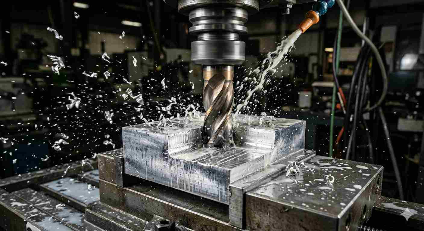
(AI generated) carbide end mill cutting an aluminum block during CNC milling operation
Most guides on types of milling operations give you a list with definitions. That's not particularly useful when you're trying to understand why one milling technique suits a job and another doesn't. The difference between face milling and peripheral milling isn't just where the cutter contacts the workpiece, it's how forces act on the part, what surface you end up with, and how efficiently you remove material.
This covers the milling processes that actually matter in production CNC machining, what makes each one behave the way it does, and when to use which.
At JLCCNC, milling machining operations are part of daily production across aerospace brackets, precision housings, fixtures, threaded components, and high-tolerance industrial parts. Different geometries demand completely different milling strategies, tooling, and cutter engagement conditions.
What Are Milling Operations?
Milling operations are CNC machining processes where rotating cutters remove material through controlled multi-axis movement.
That covers a lot of ground. The reason there are so many types of milling operations is that changing the cutter geometry, the direction of feed, the depth and width of cut, or which part of the tool is doing the cutting produces fundamentally different machining behavior, even on the same machine with similar material.
How Milling Removes Material
Unlike turning, where the workpiece rotates and the tool feeds continuously, milling is an interrupted cutting process. Each tooth on a milling cutter enters the cut, removes a chip, and exits before the next tooth engages. The chip starts thin, thickens through the cut, and exits as the tooth leaves the material, or starts thick and thins, depending on whether you're climb milling or conventional milling.
That interrupted engagement is what makes milling forces complex compared to turning. Forces aren't constant, they pulse with each tooth engagement. The frequency of that pulsing depends on the number of teeth and the spindle speed.
When that frequency matches a natural resonance of the setup, you get chatter. When it doesn't, you get stable cutting. This is why feeds, speeds, and tool selection matter so much in milling machining operations, they're not just productivity variables, they determine whether the cut is stable.
How Cutter Engagement Changes Machining Behavior
Cutter engagement is the percentage of the cutter diameter that's in contact with the workpiece during a pass. A 20mm end mill taking a full-width slot has 100% engagement, the entire diameter is cutting. The same tool taking a 4mm width of cut has 20% engagement.
Lower engagement means fewer teeth in the cut simultaneously, lower average cutting force, and less heat generation per pass. It also means higher allowable feed rates because the chip load per tooth can increase while keeping total force manageable. High-speed machining strategies exploit this, using 10-20% engagement at very high feed rates to remove material faster than a conventional full-width pass while generating less heat and force per cut.
Higher engagement means more teeth in the cut, higher forces, more heat, and typically lower allowable feed rates. Full-slot milling is one of the most demanding conditions for any end mill, it's also the least efficient material removal strategy in most situations. Understanding this relationship is what separates effective milling technique selection from defaulting to whatever worked last time.
Common Types of Milling Operations
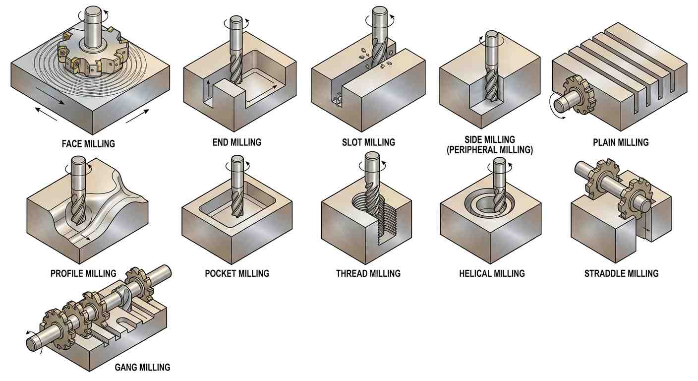
(AI generated) diagram comparing different types of milling operations
Different milling operations create very different cutting conditions, even on the same machine with the same spindle and material. What changes is cutter engagement, force direction, chip evacuation path, and how the tool contacts the workpiece. A toolpath that works well for open aluminum roughing may become unstable immediately inside a deep stainless pocket.
| Feature Type | Preferred Milling Operation |
|---|---|
| Large flat surface | Face milling |
| Deep narrow groove | Slot milling |
| Thin wall cavity | Adaptive pocket milling |
| Large internal thread | Thread milling |
| Curved aerospace contour | Profile milling |
Face Milling
Face milling is usually the first operation performed after raw stock reaches the machine. The cutter face engages the top surface while most cutting force pushes downward into the machine structure rather than sideways into the part. That matters on larger steel plates and fixture bases where rigidity determines whether the surface finishes cleanly or starts vibrating halfway through the pass.
A 63 mm face mill running carbide inserts on low-carbon steel may remove several millimeters per pass without instability if the setup is rigid enough. The same operation on thin aluminum plate behaves differently. Material flex becomes the limiting factor long before spindle power does.
Surface finish from face milling is generally better than what small end mills produce across large areas. Fewer overlaps. Lower scallop height. Less cumulative tool deflection across the surface.
End Milling
End milling is the general-purpose operation most CNC shops rely on daily because the cutter can remove material with both the side and bottom edges simultaneously. Pockets, contours, shoulders, chamfer preparation, clearance reliefs — most of these features eventually involve an end mill somewhere in the process chain.
But end milling becomes unstable quickly once tool overhang increases.
A short 12 mm carbide end mill cutting a 15 mm deep aluminum pocket may run aggressively at high feed without issue. Extend the same tool 70 mm out of the holder into stainless steel and chatter starts appearing even before full depth engagement.
Face milling and end milling often get grouped together, but cutter engagement, force direction, and achievable geometry are completely different between the two operations. Our guide on end milling vs face milling breaks down where each process works best.
Slot Milling
Slot milling is mechanically demanding because the cutter becomes trapped in near full-width engagement. Chips lose their escape path almost immediately, especially in deeper cuts. Heat rises faster than many programmers expect.
This is one reason slotting aluminum can suddenly fail after appearing stable for the first few seconds. Recut chips begin welding onto the cutting edge. Load spikes follow. Surface finish collapses after that.
Tool deflection also increases because both sides of the cutter stay engaged simultaneously. Narrow slots deeper than about 3× tool diameter usually require reduced feed, peck-style clearing, or multiple axial passes to keep the cut stable.
Full-width slotting is one of the highest load conditions for solid carbide end mills, especially once axial depth increases.
Side Milling
Side milling uses the cutter periphery to generate vertical walls, steps, and shoulders. Compared with face milling, force direction shifts more laterally into the cutter and workpiece.
That changes wall behavior.
Tall thin sections can flex away from the tool slightly during roughing, then spring back after the cutter exits. On precision housings, this sometimes leaves tapered walls even when machine positioning remains accurate.
Finishing passes are usually separated intentionally from roughing for this reason. A lighter radial cut reduces cutter deflection and stabilizes wall geometry.
Plain Milling
Plain milling is typically performed on horizontal milling setups where slab cutters remove material across broad surfaces with relatively stable engagement. Cutter diameter stays large. Tooth engagement remains predictable. Material removal rates can be extremely high on cast iron and low-alloy steel.
The operation favors rigidity more than flexibility.
Large arbor-mounted cutters generate significant cutting torque, but horizontal machines absorb those forces efficiently because spindle orientation supports the cutter differently from a vertical end mill setup.
You still see plain milling heavily used in larger production environments machining transmission housings, structural steel components, and heavy base sections.
Profile Milling
Profile milling follows external contours rather than straight linear paths. Mold cavities, turbine surfaces, aerospace ribs, die geometry — this is where cutter engagement constantly changes during motion.
Corners become the problem area.
As the tool enters a tighter radius, radial engagement increases immediately. Feed rate may remain programmed at the same value while actual chip thickness changes dramatically. Without smoothing or adaptive feed control, cutter load spikes inside corners and leaves visible blend marks.
Ball nose cutters amplify this effect further because cutting speed near the tool center drops significantly.
That is why profile finishing often prioritizes smooth motion consistency over maximum material removal rate.
Pocket Milling
Pocket milling removes material from enclosed cavities where chips, heat, and tool reach all become progressively worse as depth increases.
Open shallow pockets are usually straightforward. Deep cavities are not.
Once the pocket depth exceeds several cutter diameters, chips begin circulating around the tool instead of evacuating cleanly upward. In aluminum, recutting starts damaging the wall finish very quickly. Stainless steel behaves differently — heat concentration near the cutting edge becomes the larger issue.
Modern adaptive clearing strategies were adopted largely because conventional zig-zag roughing overloaded cutters too aggressively inside deep pockets.
Lower radial engagement leaves room for chips to escape.
Thread Milling
Thread milling generates threads through helical interpolation rather than forcing a tap through the hole. The cutter diameter remains smaller than the final thread size, which changes failure behavior completely.
If a tap breaks inside a finished aerospace bracket or hardened stainless component, the part is often scrap. A thread mill usually retracts safely even if wear begins or cutting load rises unexpectedly.
Thread milling also gives more diameter control because thread fit can be adjusted through toolpath compensation rather than changing the tool itself.
The tradeoff is cycle time. Thread milling is usually slower than rigid tapping in high-volume production.
Still, once thread size increases or material hardness rises, the stability advantage becomes significant.
Helical Milling
Helical milling gradually ramps the cutter into the material through spiral motion instead of direct plunging. The operation reduces axial shock load on the cutter and spindle during entry.
Large-diameter holes are commonly produced this way when drilling becomes inefficient or unavailable.
A 20 mm end mill can interpolate a much larger bore without requiring a dedicated drill size. More importantly, cutting load stays smoother during entry because the cutter engages progressively rather than impacting the full diameter at once.
Machines with limited spindle thrust often benefit from helical entry strategies during harder material roughing.
Straddle Milling
Straddle milling machines two parallel surfaces simultaneously using cutters mounted on the same arbor. The operation appears older compared with modern multi-axis machining, but it still solves specific production problems efficiently.
Spacing accuracy improves because both surfaces are generated in one setup under the same cutter alignment condition.
Spacer blocks, rail features, parallel mounting faces — these are still practical use cases.
The operation depends heavily on setup rigidity and arbor alignment. Once the spacing drifts, both machined faces shift together.
Gang Milling
Gang milling mounts multiple cutters onto one arbor so several features machine simultaneously during a single pass. The approach prioritizes production efficiency rather than flexibility.
Older transfer-line manufacturing used gang milling extensively before modern CNC tool changers became common. You still see it on certain dedicated production fixtures machining repeated geometries in large batches.
The advantage is cycle consolidation.
Several shoulders, grooves, or widths can be generated together without repeated tool changes or repositioning. But setup becomes more demanding because cutter spacing, axial alignment, and spindle load all increase together.
One unstable cutter affects the entire operation chain.
How Different Milling Operations Affect Machining Results
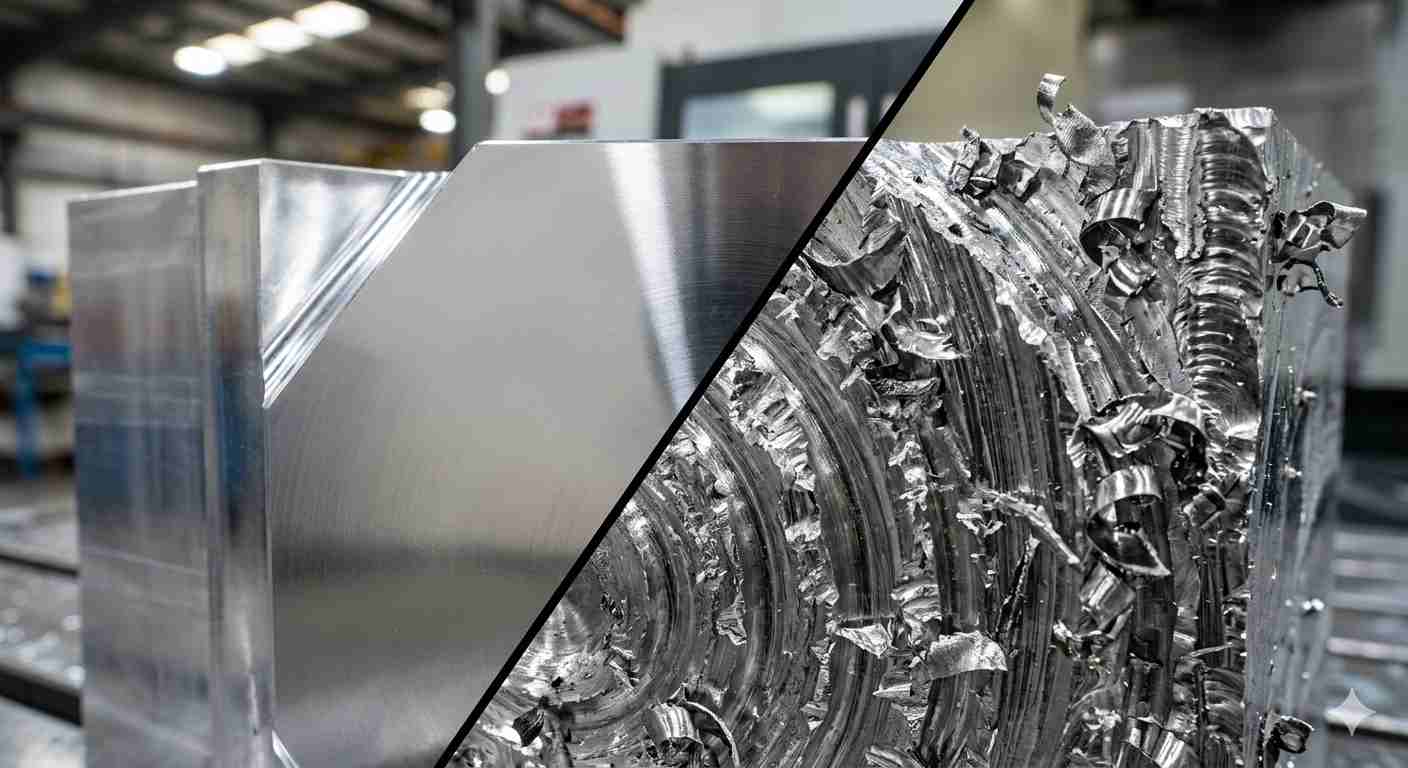
(AI generated) comparison of rough and finished CNC milled metal surfaces
The cutter path doesn't just shape the part. It changes heat generation, cutting force direction, surface quality, burr formation, and dimensional stability at the same time.
That's why two machining strategies producing the same geometry can behave completely differently on the machine.
Surface Finish and Edge Quality
Surface finish depends heavily on cutter engagement stability.
Face milling generally produces better flatness and surface consistency than small end mills across large surfaces, because the cutter diameter spreads cutting forces across multiple teeth while maintaining relatively consistent engagement. A large face mill skimming a steel plate leaves a completely different finish than a small end mill trying to cover the same area through multiple stepovers.
Slot milling tends to produce rougher finishes because chips become trapped around the cutter. Recutting chips damages the machined surface quickly, especially in aluminum where chips weld easily to the tool edge.
Profile milling introduces another challenge. Every sharp corner changes tool engagement instantly. The cutter slows mechanically as it enters tighter radii, chip thickness changes, and tool deflection shifts. If feeds aren't adjusted dynamically, corner marks and inconsistent finish appear even when the straight sections look perfect.
Burr formation changes by operation too.
Conventional side milling often pushes burrs toward the exit edge of the cut. Thin wall parts become especially sensitive because the material flexes away from the cutter slightly before the final breakthrough.
Dimensional Accuracy and Tool Deflection
Tool deflection is one of the main reasons roughing and finishing passes are separated in precision milling processes.
During heavy roughing, cutting forces physically bend the cutter slightly away from the material. Even carbide tools deflect under load. A long 6mm end mill cutting deep stainless steel pockets can move enough under force to shift wall dimensions by several hundredths of a millimeter.
Low engagement milling techniques reduce this problem because radial cutting force drops significantly. That's one reason adaptive milling strategies became popular in modern CNC machining. Lower side load means the tool stays straighter and lasts longer.
Deep slot milling is one of the worst cases for deflection because the cutter is surrounded by material on both sides. Forces increase while chip evacuation gets worse at the same time.
Then vibration enters the picture.
Once the cutter starts oscillating, dimensional stability disappears quickly. The machine may still technically hold position accurately while the tool itself moves unpredictably inside the cut.
Material Removal Rate and Machining Efficiency
Fast material removal is not automatically efficient machining.
A full-width slotting pass looks aggressive because the cutter is buried deeply in material, but it often removes material slower overall than a lighter adaptive toolpath running much higher feed rates with lower engagement.
This is where milling techniques changed dramatically over the last decade.
Traditional roughing strategies relied on large radial cuts and conservative feeds. Modern milling processes increasingly rely on constant engagement toolpaths that keep cutter load stable throughout the cut. Stable engagement lets spindle speed and feed stay high without sudden force spikes.
The result is usually better tool life, lower heat generation, and shorter cycle time simultaneously.
But only when the machine, holder rigidity, spindle power, and CAM strategy are stable enough to support it.
Choosing the Right Milling Operation
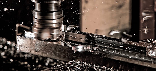
(Istock) CNC milling machining operation
Selecting a milling strategy is usually less about the machine itself and more about how stable the cut remains once the tool reaches the actual feature. Two parts made from the same material may require completely different machining approaches simply because wall thickness, cavity depth, or cutter access changes the cutting behavior.
Deep Cavities Change the Entire Machining Approach
A shallow pocket may run perfectly with a standard end mill and aggressive roughing passes. Increase the cavity depth, however, and the same setup can become unstable very quickly.
Longer tool extension increases leverage against the cutter. Chip evacuation also becomes harder as the cavity deepens. In stainless steel, heat concentration near the cutting edge usually becomes the limiting factor. Aluminum behaves differently. Recut chips and edge buildup tend to appear first.
This is why deep cavities are often roughed with lighter radial cuts and multiple step-down passes instead of heavy full-width engagement. In some cases, finishing tools are kept intentionally shorter and only used after most material has already been removed.
Thin Walls Rarely Finish Accurately Under Heavy Cutting Load
Thin sections move during machining even when the machine itself remains perfectly accurate.
A tall aluminum wall may deflect slightly away from the cutter during side milling, then recover after the tool exits the cut. The finished dimension can end up tapered even though the programmed geometry was correct.
For that reason, roughing and finishing are normally separated. Roughing leaves a small amount of stock on the wall, while lighter finishing passes reduce side pressure and improve dimensional consistency. Some parts also benefit from semi-finishing before the final pass, especially when wall height increases relative to thickness.
High-Speed Milling and Heavy Roughing Solve Different Problems
Large roughing cuts still work well on rigid setups machining cast iron or thick steel sections. A heavy face mill on a stable horizontal machine can remove material extremely efficiently under the right conditions.
High-speed milling uses a different approach entirely. Instead of maximizing cutter engagement, the tool stays in lighter contact with the material while feed rate increases significantly. This reduces heat concentration and helps maintain more stable cutting conditions in deep pockets and thin-ribbed parts.
The strategy is heavily dependent on machine capability. Weak toolholding, spindle vibration, or poor machine dynamics usually remove most of the advantage.
Production Parts Are Machined Differently From Prototype Parts
Prototype machining often prioritizes flexibility and short setup time. Production machining usually prioritizes repeatability.
A toolpath that works acceptably for five parts may become expensive across five thousand parts once tool wear, cycle balancing, and unattended runtime start affecting the process. Reducing unnecessary tool changes sometimes matters more than maximizing theoretical material removal rate.
Production setups also tend to simplify cutter variation where possible. Fewer tools, more stable offsets, and predictable spindle load generally make long production runs easier to control.
Not sure which milling technique fits your part geometry or tolerance requirements? JLCCNC CNC machining services support everything from high-speed aluminum milling to tight-tolerance steel and multi-axis production machining. Upload your CAD file to get manufacturing feedback and a fast quote for custom CNC parts.

Precision CNC Machining Service
Professional manufacturing, fast turnaround, and quality assurance.
Common Problems in Milling Operations
Most milling failures start before a tool actually breaks. Surface finish changes, spindle load fluctuates, or chips stop evacuating normally. Deep pockets, thin walls, and long-reach tools make these problems much more visible.
Chatter During Deep Milling
Chatter usually appears when tool overhang becomes too long for the cutting load. A short carbide end mill may cut steel smoothly, then begin vibrating heavily once extended deeper into a cavity.
The first signs are repeating marks on the wall surface and unstable spindle noise. Profile milling and deep pocket finishing are especially sensitive because side forces continuously push the cutter off center.
Lower radial engagement and shorter tool projection generally improve stability faster than simply reducing spindle speed.
Chip Packing in Slots and Pockets
Chip packing happens when chips stop evacuating from the cutting zone cleanly. Full-width slot milling is one of the most difficult conditions because chips become trapped around the cutter almost immediately.
In aluminum, recut chips often weld onto the cutting edge and destroy surface finish within seconds. Deep pocket milling creates similar problems once chips begin circulating inside the cavity instead of clearing upward.
Adaptive milling paths help by leaving more open space around the tool for chip evacuation.
Wall Deflection on Thin Features
Thin walls flex during cutting, especially under heavy side milling loads. After the cutter exits, the material springs back slightly, which can leave tapered walls or inconsistent dimensions.
This is common in aluminum housings, ribs, and enclosure parts with tall unsupported sections.
Roughing and finishing are usually separated intentionally. A lighter finishing pass reduces cutter pressure and improves wall accuracy significantly.
Corner Overload in Profile Milling
Internal corners increase cutter engagement suddenly. Even with constant feed rate, chip load rises sharply as the tool enters a tighter radius.
The result is often visible as blend marks, localized chatter, or overcut corners. Ball nose tools become even more sensitive because cutting speed drops near the tool center.
Modern CAM strategies reduce corner overload through smoother toolpaths and controlled engagement transitions.
How CNC Machine Capability Influences Milling Operations
(Istock) The 5 axis CNC machine cutting the sample part with the solid ball end mill.
A milling strategy that works perfectly on one machine can fail completely on another.
Not because the CAM software changed. Not because the cutter changed. Because the machine itself changes how stable the cut remains under load.
Rigidity, spindle power, axis acceleration, toolholding quality, and machine geometry all influence what milling techniques actually work in production.
3-Axis vs 5-Axis Milling Limitations
3-axis machining handles most milling operations well until tool access becomes difficult.
The problem appears when deep walls, compound angles, or curved geometry force long tool overhangs. The farther the cutter extends from the holder, the more leverage cutting forces gain against the tool.
That's where 5-axis machining changes things.
Instead of forcing a long cutter vertically into difficult geometry, the machine tilts the spindle or the part to keep the tool shorter and more rigid relative to the cutting surface.
A turbine blade is the classic example.
Trying to finish deep blade geometry on a 3-axis machine often requires extremely long ball nose tools that chatter easily. A 5-axis machine keeps the cutter angled into the surface so a much shorter tool can reach the same geometry with better stability and finish quality.
But 5-axis machining introduces its own complexity.
Machine dynamics become more sensitive, programming becomes harder, and small post-processing errors create major motion problems quickly. More capability does not automatically mean easier machining.
Tool Reach, Rigidity, and Cutter Overhang
Tool overhang quietly controls a huge percentage of milling stability problems.
A short 12mm carbide end mill cutting 20mm deep steel behaves completely differently from the same cutter extended 80mm out of the holder. The cutter itself hasn't changed. The leverage acting against it has.
Deflection increases fast with overhang length.
That affects surface finish first, then dimensional accuracy, then eventually tool life and chatter stability. Long tools also lower the safe material removal rate because cutting forces have to stay lower to avoid vibration.
Deep cavities expose this problem constantly.
A pocket may rough perfectly with a short tool until the final floor depth requires a longer extension. Suddenly the exact same feeds and speeds start producing chatter and inconsistent finish.
Holder selection matters too.
Hydraulic holders, shrink-fit systems, and high-quality collet systems generally improve rigidity and runout compared to worn basic holders. At aggressive spindle speeds, even slight runout changes tooth loading enough to shorten tool life noticeably.
That's why advanced milling techniques are heavily dependent on machine capability.
The strategy only works if the machine, spindle, holder, and setup are stable enough to support it.
Conclusion About All Milling Operations
The different types of milling operations are really different ways of controlling cutter engagement, cutting force, heat, and geometry access during machining.
Face milling, slot milling, profile milling, pocket milling, and other milling techniques all exist because different part features create different machining conditions. The best operation is usually the one that keeps the cut stable while producing the required geometry with the least unnecessary complexity.
Understanding how milling processes behave under real cutting conditions matters far more than memorizing operation names.
At JLCCNC, CNC milling operations are selected based on part geometry, tolerance requirements, surface finish targets, and production efficiency rather than default toolpaths. From high-speed aluminum roughing to precision stainless steel finishing, stable milling strategy is what ultimately determines part quality, tool life, machining consistency, and production cost across different manufacturing volumes.
Upload your CAD file to get a fast quote starting from $1, with lead times as short as 3 days.
Precision CNC Machining Service
Professional manufacturing, fast turnaround, and quality assurance.
FAQ About Milling Operations
Q: Why does slot milling chatter more easily than face milling?
Slot milling traps the cutter in near full-width engagement, which increases cutting force, heat, and tool deflection compared to face milling’s lighter engagement.
Q: What milling operation removes material fastest?
High-feed face milling and rough pocket milling with low radial engagement usually deliver the highest material removal rates in CNC production.
Q: Why is thread milling more accurate than tapping?
Thread milling lets the machine control thread diameter through toolpath adjustment, while tapping depends entirely on the tap size and alignment.
Q: Which milling operations generate the most heat?
Full-width slot milling, deep pocket milling, and heavy side milling generate the most heat because chip evacuation becomes restricted and cutter engagement stays high.
Q: What milling strategy works best for thin walls?
Low radial engagement with multiple light finishing passes works best because it reduces wall deflection and vibration during cutting.
Q: Why do deep pockets cause tool deflection?
Deep pockets require longer tool overhang, and longer tools flex more under cutting load, which reduces dimensional accuracy and surface quality.
Popular Articles
• Cutting with Precision: A Comprehensive Guide to CNC Water Jet Technology
• CNC Coolant Explained: Types, Maintenance & Safety
• Rake Angle in Machining: Machinists’ Guide to Perfect Cuts
• What Steps Are Taken To Minimize Waste In CNC Machining Processes?
• How EDM Wire Cutting Works: Complete Guide to Precision CNC Wire Cutting
Keep Learning
Chatter in Machining: Causes, Effects, and How to Reduce It
CNC milling operation producing visible chatter marks on an aluminum workpiece Quick Chatter Diagnosis Checklist Symptom Most Likely Cause First Action High-pitched squeal Regenerative chatter Change spindle speed ±15% Chatter only in deep pockets Excessive tool overhang Shorten tool Chatter on thin walls Low workpiece rigidity Improve fixturing Chatter after tool replacement Runout / holder issue Check tool holder Chatter only during finishing DOC too small / rubbing Increase feed or adjust speed It ......
What Is Tool Offset in CNC? Types, Setup & Best Practices
CNC tool offset setup with measurement overlay Key Takeaways CNC offsets connect programmed intent with actual cutter position. Length data guides Z-axis depth control. Radius data protects part size during contour milling. Geometry values define the cutter's measured baseline. Wear values support fine correction during production. Verified data lowers scrap risk before full machining. Good offset habits protect tools, fixtures, and parts. In the context of CNC machining , tool offset is the quiet set......
Trochoidal Milling: Complete Guide to High-Efficiency CNC Machining
Key Takeaways Trochoidal milling combines circular cutter motion with continuous forward feed. The cutter normally engages 5 to 20% of its diameter instead of making a full-width cut. A smaller engagement angle limits force changes during slotting and pocket roughing. Low radial engagement often allows greater axial depths of cut than conventional slot milling. CAM software calculates the circular path automatically from the selected machining parameters. This strategy is widely applied to titanium, s......
What Is Die Casting? Process, Materials, and Applications
Key Takeaways Die casting is a metal casting process that forces molten metal into a reusable steel mold under high pressure, producing parts with tight tolerances and good surface finish at high volume. Aluminum die casting is the most common form by far, thanks to its combination of light weight, decent strength, and good corrosion resistance. The die casting process runs through mold preparation, injection, cooling, and ejection in a cycle that can repeat every few seconds to minutes depending on p......
First Angle vs Third Angle: Understanding Orthographic Projection Methods
Key Takeaways Orthographic projection is the system that lets a 3D part be represented through multiple 2D views, front, top, side, and so on. First angle projection and third angle projection are the two standard methods for arranging those views, and they place views in opposite positions relative to the object. First angle projection is the ISO standard used across most of Europe, India, China, Russia, and many other countries following ISO standards Third angle projection is the standard in the Un......
Micro EDM Machining: Capabilities, Materials, and Applications for Precision Components
Key Takeaways About Micro EDM Machining Only electrically conductive materials can be machined. Hole diameters can reach below 50 μm on specialized equipment. The process produces almost no mechanical cutting force, making it suitable for thin or delicate features. Surface integrity still requires attention because recast layers and heat-affected zones may remain after machining. Micro EDM is often combined with CNC machining, with milling producing the main geometry before EDM finishes critical micro......