What Is Plain Milling? Process, Plain Milling Cutters, and Key Advantages
26 min
- What Is Plain Milling?
- How Plain Milling Works
- Plain Milling vs Face Milling vs End Milling
- What Are Plain Milling Cutters?
- What Are the Main Types of Plain Milling Cutters?
- Advantages and Limitations of Plain Milling
- Key Parameters in Plain Milling
- Machines, Setup, and Workholding for Plain Milling
- Materials and Performance Optimization in Plain Milling
- Applications of Plain Milling
- Plain Milling Services at JLCCNC
- Common Problems in Plain Milling (and How to Fix Them)
- FAQ About Plain Milling
Key Takeaways
• Plain milling is a horizontal milling process used to machine wide, flat surfaces with stable cutting and consistent material removal.
• Plain milling cutters remove material with their cylindrical outer diameter, making them well suited for base plates, reference surfaces, and stock preparation.
• The main types of plain milling cutter include straight-tooth, helical-tooth, light-duty, and heavy-duty cutters, each suited to different loads and finish requirements.
• Key factors in the plain milling process include cutter selection, feed direction, arbor rigidity, and workholding stability.
• The main advantages of plain milling are high efficiency on flat surfaces, strong rigidity, and good dimensional consistency, while its main limitation is low flexibility for complex geometry. directly affect machining difficulty, quality, and cost.
• In plain milling in manufacturing, the process is most effective for large, simple, flat features and is often compared with face milling and end milling during process selection.
What Is Plain Milling?
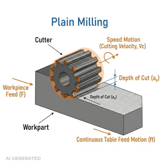
Diagram of a cylindrical plain milling cutter mounted on a horizontal arbor
Plain milling is often overlooked because it is straightforward and reliable. It is widely used to machine flat surfaces with consistent material removal and stable cutting forces, and it often serves as the foundation for later precision operations.
The cutter runs horizontally, parallel to the surface being machined. That orientation is important. Material comes off along the cylindrical face of the tool, not the end, which spreads cutting forces across multiple teeth at once. Less vibration, better stability, cleaner results on larger surfaces.
It's also different from face milling in a way that actually affects how you set the job up. Face milling cuts primarily with the tool face. Plain milling cuts with the body. That changes chip formation, force direction, and how the setup needs to be supported.
In production it shows up wherever you need a flat, reliable surface to work from, base plates, mounting faces, stock preparation before finishing. Not glamorous work, but get it wrong and everything downstream pays for it.
The results depend on three things more than anything else: cutter selection, feed rate, and how rigid the setup is. The process is simple but the discipline around it isn't.
Purpose of Plain Milling in Manufacturing
Plain milling exists in manufacturing not because it is complex, but because it is reliable.
In most production workflows, it serves as a primary machining step used to establish a flat reference surface before secondary operations such as face milling, drilling, or boring. This reference surface acts as a datum, ensuring that all subsequent machining steps are aligned and dimensionally consistent.
It is also widely used for stock preparation. By removing large amounts of material across wide, flat areas in a stable way, plain milling creates a uniform baseline that simplifies downstream operations and reduces tolerance stack-up.
Importantly, plain milling is not typically a final finishing process. Instead, it controls flatness at an early stage, providing a consistent foundation that improves both machining accuracy and overall process efficiency.
In real production, this level of control usually comes down to setup experience.
At JLCCNC, plain milling is commonly used to create stable reference surfaces before finishing operations, with a focus on cutter selection and workholding to keep results consistent.

Precision CNC Machining Service
Professional manufacturing, fast turnaround, and quality assurance.
How Plain Milling Works
The cutter rotates. The workpiece feeds linearly into it. That's the motion, but the mechanics underneath that motion are what separate a stable, efficient cut from one that chatters, wears tools prematurely, or leaves a surface that needs rework.
Conventional vs Climb
Feed direction relative to cutter rotation isn't a preference. It changes the force vector acting on the workpiece, chip geometry, and tool life in ways that compound across a production run.
In conventional milling, the cutter opposes feed direction. Chip thickness starts near zero and increases through the cut. That gradual engagement means the tool doesn't bite immediately, it rubs slightly before cutting, which generates more heat at the edge and accelerates flank wear. On older machines with lead screw backlash, conventional is still the safer choice because the cutting force pushes against the feed direction, keeping the table loaded consistently without chatter from backlash-induced movement.
Climb milling reverses that. Chip thickness starts at maximum and reduces. The tool bites immediately, heat transfers into the chip rather than the workpiece, and flank wear drops noticeably. In aluminum, tool life improvements of 20–30% over conventional are common when climb milling conditions are properly controlled. Surface finish also improves because the cutter isn't rubbing at entry. Ra values in the 1.6–3.2 µm range are achievable in climb milling where conventional on the same setup might land at 3.2–6.3 µm.
The catch is rigidity. Climb milling pulls the workpiece into the cutter. On a machine with any table play or loose fixturing, that pull creates a self-feeding condition, the table lurches forward, chip load spikes, and either the tool breaks or the surface gets gouged. On a rigid CNC machining center with ballscrew drives and proper workholding, climb milling is almost always the better choice for finishing passes.
We cover this in more depth in our dedicated Climb vs Conventional Milling guide.
The Arbor Setup
Plain milling runs on a horizontal spindle with the cutter mounted on an arbor supported at both ends by the overarm and bearing support. That dual support is not incidental, it's the structural reason plain milling handles wide, heavy cuts that cantilevered tooling can't.
A cantilevered end mill deflects under radial load. That deflection is proportional to the cube of the overhang length, double the stick-out, and deflection increases eightfold at the same cutting force. An arbor-mounted plain milling cutter eliminates that variable almost entirely. Arbor-mounted cutters generally show much lower deflection than cantilevered tooling under comparable cutting loads, even on heavy cuts, which is why dimensional consistency across wide surfaces is far more achievable with this setup than with cantilevered tooling.
Arbor diameter matters here. Common sizes run 22mm, 27mm, and 32mm for lighter operations, with 40mm and 50mm arbors used for heavier cuts in steel. A larger arbor diameter provides substantially higher bending stiffness, which improves surface consistency and dimensional stability in wide cuts. For wide cutters taking full-width passes, that stiffness difference shows up directly in surface finish and dimensional stability.
How Material Actually Comes Off
The cutter is cylindrical. Teeth engage the workpiece in sequence, each tooth enters the cut, removes a chip, and exits before the next tooth engages. At typical plain milling speeds, that happens fast enough that the cutting action feels continuous, but the load distribution across teeth is what makes it mechanically stable.
Chip load per tooth is the parameter that controls everything downstream, surface finish, tool life, cutting forces, heat generation. For plain milling in steel, chip loads typically run 0.05–0.15mm per tooth depending on cutter diameter and material hardness. In aluminum, that range extends to 0.1–0.3mm per tooth before surface finish degrades. Running below the minimum chip load can be as damaging as running above it. If the chip is too thin, the tool rubs rather than cuts, generating heat without productive material removal and accelerating edge wear faster than a properly loaded cut would.
Cutting speed follows material. For HSS plain milling cutters in mild steel, surface speeds in the 20–30 m/min range are standard. Carbide-tipped cutters push that to 80–150 m/min in the same material. In aluminum with carbide, 300–600 m/min is achievable on rigid setups. Those aren't arbitrary ranges, they're driven by the temperature at the cutting edge. Cutting speed is limited by the thermal stability of the tool material, which is why recommended ranges differ significantly between HSS and carbide cutters.
Width of cut in plain milling typically runs full cutter width for roughing, that's where the process efficiency comes from. For finishing passes, cutter engagement is often reduced to lower cutting force and improve surface consistency, and increasing feed slightly improves surface finish by reducing the scallop height left between tooth passes. On a flat reference surface where Ra below 1.6 µm is required, that adjustment often eliminates the need for a separate grinding operation.
Plain Milling vs Face Milling vs End Milling
If you’re choosing between these three, the difference isn’t just tool shape
| Factor | Plain Milling | Face Milling | End Milling |
|---|---|---|---|
| Cutter orientation | Horizontal (parallel to surface) | Vertical (perpendicular to surface) | Vertical or multi-axis |
| Surface type | Large flat surfaces | Flat faces, especially wide areas | Slots, pockets, contours |
| Material removal method | Cylindrical cutter removes material along its side | Cutting mainly occurs at tool face | Cutting occurs at tool tip and sides |
| Typical applications | Base plates, reference surfaces, stock preparation | Surface finishing, facing operations | Complex geometry, features, cavities |
| Efficiency | High for wide, flat surfaces | High for surface finishing | Lower for large flat areas, higher for complex parts |
For a deeper breakdown of how face milling works and when to use it, read our Face Milling Guide or face milling vs end milling
When to Use Plain Milling
Use the plain milling process when you need to machine large, flat surfaces with stability and consistency.
It works best when the cutter can engage across the full width of the part. The horizontal setup and arbor support reduce deflection, which helps maintain flatness over larger areas.
In plain milling in manufacturing, this is often the first step. You establish a reference surface, remove bulk material, and prepare the part for tighter operations later.
If your part is simple, wide, and flat, plain milling is usually the most efficient option.
When NOT to Use Plain Milling
Plain milling breaks down when geometry becomes complex.
If your part has pockets, slots, or 3D contours, end milling is the better choice. The tool needs to access features from different angles, which a horizontal cutter cannot do effectively.
For finishing large flat faces with tighter surface requirements, face milling is often preferred. It provides better surface finish and more controlled cutting at the top surface.
So the decision is straightforward.
Use plain milling for wide, flat surfaces with straightforward geometry.
Avoid it when the part requires detail, depth variation, or multi-axis access.
Understanding the cutter design is essential because plain milling performance depends heavily on cutter geometry and tooth configuration.
What Are Plain Milling Cutters?
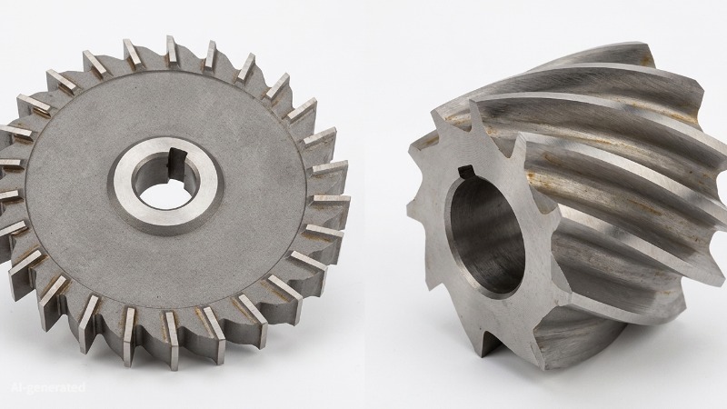
(AI generated) Plain milling cutters
A plain milling cutter is a cylindrical multi-tooth tool that removes material along its outer diameter. That description is accurate but doesn't tell you much. What actually matters is how the geometry of that cylinder, tooth count, helix angle, width, material, coating, determines whether a cut is stable, efficient, and repeatable, or whether you're fighting chatter, premature wear, and inconsistent finish.
Structure and Geometry
The cutter body is either solid or assembled, with teeth ground around the circumference. On smaller diameter cutters under 63mm, solid HSS or carbide construction is standard. Above that, inserted-tooth designs become more common, carbide inserts in a steel body, which reduces cost per edge and allows individual insert replacement without scrapping the whole tool.
Teeth can be straight or helical. Straight teeth are simpler to manufacture and resharpen, but they engage the full tooth width simultaneously. That simultaneous engagement creates an impact load every time a tooth enters the cut, manageable at low cutting forces, but it becomes a vibration source as depth of cut or feed increases. Straight-tooth cutters are still used in light finishing operations and on materials where helical geometry creates unwanted axial thrust.
Helical teeth solve the impact problem by staggering engagement across the tooth length. Instead of the full edge hitting at once, contact starts at one end and travels progressively across the width. That progressive engagement smooths cutting forces significantly. Helix angles on plain milling cutters typically run between 15° and 45°. At 15–25°, the axial force component is manageable and the smoothing effect is meaningful. At 30–45°, chatter resistance improves further but axial thrust increases, at 45° helix, axial force can equal radial force, which matters for arbor selection and workholding design.
Tooth count is a direct function of cutter diameter and application. Coarse-tooth cutters run 4–6 teeth on a 75mm diameter cutter, designed for heavy roughing where chip clearance matters more than surface finish. Fine-tooth cutters on the same diameter might carry 10–14 teeth, reducing chip load per tooth and improving finish at the cost of gullet space. Running a fine-tooth cutter at high feed rates in a gummy material like low-carbon steel or aluminum with poor chip evacuation packs the gullets and ruins the cut, coarse tooth geometry exists for a reason.
How Cutter Geometry Controls Performance
Cutter width determines pass coverage but it isn't a free variable. Wider cutters increase material removal rate proportionally, but cutting force scales with width as well. A 100mm wide cutter taking a full-width pass in steel generates roughly twice the radial force of a 50mm cutter at the same chip load per tooth. That force increase loads the arbor, the spindle bearings, and the workholding, all of which have limits. In practice, full-width passes with wide cutters are reserved for roughing on rigid horizontal mills with adequate spindle power. Semi-finishing and finishing passes often use 60–75% of cutter width to reduce force and improve surface consistency.
Helix angle affects more than just vibration. It controls how chips evacuate and where heat goes. A higher helix angle directs chips axially, away from the cut zone, which improves cooling and reduces the chance of chip recutting. In aluminum, where chip recutting damages surface finish rapidly, helix angles of 35–45° are standard. In harder steels where axial thrust is a concern and chip volume is lower, 15–25° is more common.
Rake angle at the tooth face controls how aggressively the cutter shears material. Positive rake angles, typically 5–15° on carbide cutters for steel, reduce cutting forces and heat generation but sacrifice edge strength. Negative rake angles increase edge strength at the cost of higher cutting forces, used on hardened materials or interrupted cuts where edge chipping is the primary failure mode. Most general-purpose plain milling cutters for steel run 8–12° positive rake as a balance point.
Material and Coating
HSS cutters are still viable for low-volume work, softer materials, and operations where resharpening cost justifies the lower initial price. Cutting speeds for HSS in mild steel top out around 25–35 m/min before thermal softening accelerates wear. Above that, you need carbide.
Carbide plain milling cutters operate at 80–200 m/min in steel and 300–600 m/min in aluminum, depending on grade and coating. The grade matters, a fine-grain carbide with 10% cobalt binder handles interrupted cuts and variable hardness better than a harder, more brittle grade optimized for continuous cutting in homogeneous material. Specifying carbide without specifying grade is like specifying steel without specifying grade.
Coatings extend tool life by reducing friction and thermal conductivity at the cutting edge. TiN was the standard for decades, it reduces friction and improves wear resistance modestly. TiAlN has largely replaced it for steel cutting because it forms an aluminum oxide layer at high temperatures that actually insulates the substrate, allowing higher cutting speeds without edge breakdown. In aluminum, TiAlN performs poorly, the aluminum oxide layer bonds to the workpiece material. For aluminum, uncoated carbide or DLC coatings are the better choice. Running TiAlN in aluminum is a common mistake that shows up as built-up edge and poor surface finish.
Matching Cutter to Application
The selection isn't complicated once the parameters are clear. Material determines speed range and coating. Surface finish requirement determines tooth count and helix angle. Depth and width of cut determine the rigidity requirement, which feeds back into arbor diameter and machine selection. Width of part determines cutter width, balanced against the force capacity of the setup.
Where most selection errors happen is on tooth count, either running too fine a tooth pitch in a gummy material and packing gullets, or running too coarse a pitch on a finishing pass and leaving scallop marks that require a separate operation to clean up. Getting tooth count right for the material and operation is often worth more than any coating or grade upgrade.
Getting the process right on paper is one thing. Getting it right on your actual part is another. If you're working on a job that needs flat, accurate surfaces with controlled tolerances, upload your files and let our engineers take a look. No commitment, just a fast quote from people who've read the same drawing you have.
What Are the Main Types of Plain Milling Cutters?
The types of plain milling cutter you choose change how the cut behaves. Load distribution, vibration, surface finish, and material removal rate all depend on cutter geometry and build.
Cutter Types and Where They Fit
| Cutter Type | Tooth Design | Load Capacity | Surface Finish | Typical Use |
|---|---|---|---|---|
| Straight-tooth cutter | Teeth parallel to axis | Moderate | Rougher | General-purpose, simple setups |
| Helical-tooth cutter | Teeth at an angle (helix) | Higher | Smoother | Production work, stable cutting |
| Light-duty cutter | Smaller teeth, lower mass | Low to medium | Better control | Thin parts, lighter cuts |
| Heavy-duty cutter | Larger teeth, rigid body | High | Rougher at high MRR | Bulk material removal |
Straight-Tooth vs Helical-Tooth Cutters
Straight-tooth cutters engage the material abruptly. Each tooth hits the workpiece at once across its width. That creates higher impact forces and more vibration, especially at higher feed rates.
Helical cutters enter the cut gradually. The angled teeth spread contact over time, which reduces shock loading. This improves stability, reduces chatter, and produces a better surface finish.
That’s why in real plain milling in manufacturing, helical cutters are preferred for most production work. Straight-tooth cutters still show up in simpler jobs where cost and setup matter more than finish.
Light-Duty vs Heavy-Duty Plain Milling Cutters
Light-duty cutters are built for control. They work well on softer materials or thinner parts where excessive force could cause deflection or distortion.
Heavy-duty cutters are built for load. They remove more material per pass and handle higher cutting forces, but they require a rigid machine and solid workholding.
If your setup isn’t rigid enough, a heavy-duty cutter will amplify vibration instead of improving productivity. That’s where many setups fail.
How to Choose the Right Cutter Type
If you’re machining wide, flat surfaces at higher removal rates, a helical heavy-duty cutter keeps the process stable and productive.
If you’re working on thinner sections or need better control over deflection, a light-duty cutter reduces cutting force and improves dimensional accuracy.
If surface finish matters, helix angle becomes the deciding factor. If removal rate matters, tooth size and cutter rigidity take priority.
In the plain milling process, cutter selection is what connects machine capability to part requirements. Get that wrong, and everything downstream suffers, tool life, finish, and cycle time.
For surface finish targets and how to spec them correctly, see our Surface Finish guide
Advantages and Limitations of Plain Milling
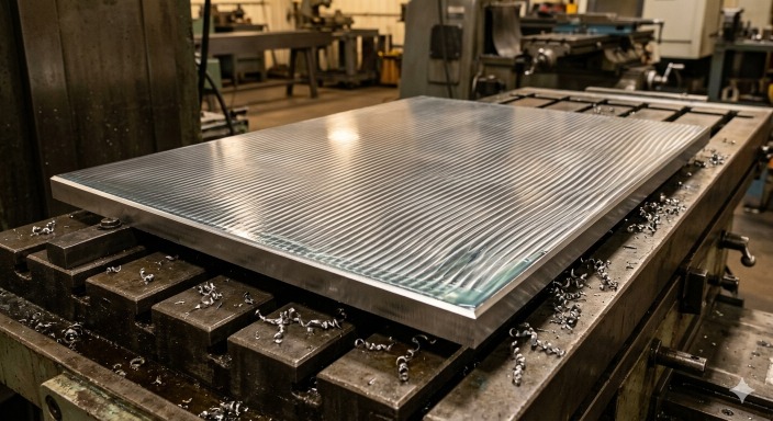
(AI generated) Large flat steel base plate freshly machined
Advantages of Plain Milling
High Efficiency for Flat Surfaces
Plain milling is built for surface coverage. A wide cutter can machine the full width in one pass, which cuts cycle time significantly. In shop data from horizontal milling lines, plain milling reduces machining time on large plates by 20–40% compared to multiple end milling passes.
In one fixture plate case, switching from end milling to a 100 mm helical plain milling cutter reduced cycle time from 18 minutes to 11 minutes for the same surface.
Stable Cutting Process
The arbor-supported setup increases rigidity. Less tool overhang means less deflection. That directly improves dimensional consistency.
In practice, shops report 15–25% reduction in chatter-related defects when switching from unsupported cutters to arbor-mounted plain milling cutters on wide surfaces.
Suitable for Heavy Material Removal
Plain milling handles higher depth of cut and feed rates because of continuous tooth engagement.
Compared to face milling in roughing scenarios, it can achieve material removal rates (MRR) 1.2× to 1.5× higher on flat stock, especially in carbon steel.
In a gearbox housing roughing case, a heavy-duty helical cutter removed 6 mm per pass with stable load, cutting roughing time by roughly 30%.
Simple Tooling and Setup
The setup is straightforward. Mount the cutter on an arbor, align the workpiece, and run. No complex toolpaths or multi-axis programming.
Setup time is often 30–50% lower than multi-tool end milling operations for similar flat features.
This matters in low-mix production where setup time directly impacts cost.
Limitations of Plain Milling
Limited to Flat Surfaces
The process is geometry-restricted. It works best on planar faces. Once the part includes steps, pockets, or curvature, the cutter cannot maintain proper engagement.
Not Suitable for Complex Geometries
You can’t machine internal features, slots, or contours with plain milling. Those require end mills or multi-axis strategies. Trying to force plain milling into these cases leads to poor access and wasted time.
Requires Horizontal Setup
Plain milling depends on a horizontal spindle and arbor support. Not every shop has horizontal machines available. This limits flexibility, especially in CNC environments dominated by vertical machining centers.
Less Flexible Than End Milling
In mixed-feature parts, relying only on plain milling increases setup changes and tool swaps, which adds indirect cost.
Key Parameters in Plain Milling
Cutting Speed, Feed Rate, Depth of Cut
These three control how aggressively the plain milling process removes material.
Cutting speed sets the thermal load. Too high, and tool wear accelerates. Too low, and productivity drops. For carbon steel, typical ranges sit around 80–180 m/min for carbide cutters, depending on rigidity and coolant.
Feed rate controls chip thickness. Increase feed, and you increase material removal rate. But push too far, and cutting forces spike. In production, adjusting feed alone can change cycle time by 15–25% without changing tooling.
Depth of cut is where plain milling shows strength. Horizontal setups can handle deeper cuts than most vertical setups. Shops commonly run 3–8 mm depth of cut in roughing without instability, depending on cutter width and machine power.
In one base plate job, increasing depth from 3 mm to 6 mm reduced total passes by half and cut machining time by ~30%, with no loss in stability due to arbor support.
Width of Cut and Tool Engagement
Width of cut defines how much of the cutter is engaged with the material.
Full-width engagement increases productivity but also raises cutting forces. Partial engagement reduces load but increases passes and cycle time. The balance depends on machine rigidity and cutter design.
In plain milling in manufacturing, wide cutters are used to cover the entire surface in one pass. That’s where the process gains efficiency. However, improper engagement can cause uneven load distribution, leading to vibration or tool wear.
A properly matched cutter width and engagement strategy can improve tool life by 20–35% while maintaining output.
Surface Finish and Dimensional Control
Surface finish in plain milling depends on feed per tooth, cutter geometry, and machine stability.
Higher feed rates increase productivity but leave visible tool marks. Lower feed improves finish but slows production. Helical cutters help maintain smoother finishes by reducing impact forces.
Dimensional control comes from rigidity. The arbor-supported cutter reduces deflection, which helps maintain flatness across large surfaces.
In practice, plain milling can achieve surface finishes in the range of Ra 1.6–3.2 µm in standard conditions, with tighter results possible under controlled parameters.
Machines, Setup, and Workholding for Plain Milling
Horizontal Milling Machines
The plain milling process is built around horizontal milling machines.
The horizontal spindle allows cutters to engage the workpiece across its width. This orientation improves chip evacuation and reduces tool deflection compared to vertical setups.
In production environments, horizontal machines handling plain milling operations often show 10–25% higher throughput on flat surface machining compared to equivalent vertical setups.
Arbor Support and Cutter Mounting
The arbor is what makes plain milling stable.
Instead of holding the cutter at one end, the arbor supports it along its axis. This reduces bending and keeps the cutter aligned under load.
In heavy-duty applications, proper arbor support can reduce tool deflection by 30% or more, which directly improves surface quality and tool life.
Workholding and Fixturing
Workholding defines whether the process stays stable or not.
Flat surfaces require uniform support. If the part is not properly clamped, cutting forces can lift or shift it, affecting accuracy.
Rigid fixturing reduces vibration and ensures consistent material removal. In large plate machining, improved fixturing alone has been shown to reduce dimensional variation by up to 20%.
The goal of plain milling in manufacturing is simple. Keep the tool stable, keep the part stable, and the process stays predictable.
Materials and Performance Optimization in Plain Milling
Materials Suitable for Plain Milling
Material choice directly changes how the plain milling process behaves. Cutting force, chip formation, and tool wear all shift depending on hardness and ductility.
| Material | Machinability | Cutting Behavior | Typical Use in Plain Milling |
|---|---|---|---|
| Carbon Steel | Medium | Stable cutting, moderate tool wear | Base plates, structural parts |
| Alloy Steel | Lower | Higher cutting forces, heat generation | Load-bearing components |
| Aluminum | High | Low cutting force, fast material removal | Lightweight plates, housings |
| Brass | Very high | Smooth cutting, excellent surface finish | Precision flat components |
How Material Properties Affect Cutting Performance
Harder materials increase cutting force and heat. That shortens tool life and limits feed rates.
Softer materials allow higher speeds, but they introduce other issues like built-up edge, especially in aluminum if cutting conditions aren’t controlled.
Material choice doesn’t just affect cost. It defines how aggressive your parameters can be and how stable the process remains.
How to Improve Plain Milling Performance
Reduce Vibration and Chatter
Chatter usually comes from poor rigidity. Use shorter tool setups, proper arbor support, and stable fixturing. Even small improvements in rigidity can extend tool life by 20% or more.
Optimize Cutter Selection
Match cutter type to the job. Helical cutters improve stability and finish. Heavy-duty cutters increase removal rate. The wrong cutter increases load and reduces efficiency.
Improve Workholding Stability
Flat surfaces need uniform support. If the part shifts or lifts, accuracy drops immediately. Strong, even clamping reduces variation and keeps the cut consistent.
Applications of Plain Milling
Flat Surfaces and Base Plates
Plain milling is widely used to establish reference surfaces.
In one fixture plate case, a horizontal plain milling setup machined a 600 mm steel plate flat within tolerance in a single pass. The same job with end milling required multiple passes and added alignment steps.
Machine Components and Structural Parts
Large components like frames and supports rely on flatness for assembly.
A gearbox housing base, for example, is often plain milled first to create a stable reference before any precision boring or drilling begins. Without that flat surface, downstream operations lose accuracy.
Large Workpieces Requiring Stable Cutting
Plain milling is preferred for heavy parts where vibration becomes a problem.
In a large machine bed application, switching to a helical plain milling cutter reduced chatter marks and improved consistency across the full surface. The process stayed stable even at higher material removal rates.
Plain Milling Services at JLCCNC
Most machine shops will run your part. Fewer will tell you before they run it that the geometry, tolerances, or setup could be done better.
At JLCCNC, plain milling jobs go through an engineering review before anything gets scheduled. That's not a sales pitch, it's just how we avoid the back-and-forth that wastes your time and ours. If there's a smarter way to hold the part, a tolerance that's tighter than the application needs, or a process that suits the geometry better, we'll flag it before it costs you anything.
Precision CNC Machining Service
Professional manufacturing, fast turnaround, and quality assurance.
Common Problems in Plain Milling (and How to Fix Them)
Even though the plain milling process is straightforward, small issues in setup or parameter selection can quickly affect surface quality, tool life, and overall efficiency. Most problems trace back to a few controllable factors.
Chatter Marks on the Surface
Chatter is usually a rigidity problem. Insufficient arbor support, excessive tool overhang, or weak workholding allows vibration to build up during cutting.
Fix: Improve arbor support, reduce overhang, and ensure the workpiece is clamped evenly and securely.
Poor Surface Finish
Surface finish issues are often caused by incorrect feed per tooth. Too low, and the tool rubs instead of cutting. Too high, and visible tool marks appear.
Fix: Adjust feed per tooth to match the cutter geometry and material, and consider using a helical cutter for smoother engagement.
Tool Wear Too Fast
Premature tool wear is typically linked to cutting speed and coating mismatch. Running too fast for the tool material, or using the wrong coating for the workpiece, accelerates edge degradation.
Fix: Match cutting speed to tool material (HSS vs carbide) and select coatings appropriate for the material (e.g., avoid TiAlN in aluminum).
Chip Packing and Poor Chip Evacuation
Chip packing happens when there isn’t enough space for chips to evacuate, especially with fine-tooth cutters in ductile materials like aluminum. This leads to recutting and surface damage.
Fix: Use a coarser tooth pitch, increase chip load appropriately, and ensure chips can clear the cutting zone effectively.
FAQ About Plain Milling
Q: What is plain milling
Plain milling is a machining process where a rotating cylindrical cutter removes material from a flat surface using a horizontal spindle, producing uniform, parallel surfaces.
Q: What is a plain milling cutter
A plain milling cutter is a multi-tooth cylindrical cutting tool mounted on an arbor, designed to remove material along its outer diameter during flat surface machining.
Q: What are the advantages of plain milling
Plain milling offers high material removal rates, stable cutting due to arbor support, and efficient machining of large flat surfaces with consistent results.
Q: What is the difference between plain milling and face milling?
Plain milling cuts with the side of a horizontal cutter for wide surfaces, while face milling uses the tool face on a vertical spindle for better surface finish and finishing operations.
Q: When should plain milling be used
Plain milling should be used when machining large, flat surfaces where stability, efficiency, and consistent material removal are more important than complex geometry.
Popular Articles
• Cutting with Precision: A Comprehensive Guide to CNC Water Jet Technology
• CNC Coolant Explained: Types, Maintenance & Safety
• Rake Angle in Machining: Machinists’ Guide to Perfect Cuts
• What Steps Are Taken To Minimize Waste In CNC Machining Processes?
• How EDM Wire Cutting Works: Complete Guide to Precision CNC Wire Cutting
Keep Learning
Chatter in Machining: Causes, Effects, and How to Reduce It
CNC milling operation producing visible chatter marks on an aluminum workpiece Quick Chatter Diagnosis Checklist Symptom Most Likely Cause First Action High-pitched squeal Regenerative chatter Change spindle speed ±15% Chatter only in deep pockets Excessive tool overhang Shorten tool Chatter on thin walls Low workpiece rigidity Improve fixturing Chatter after tool replacement Runout / holder issue Check tool holder Chatter only during finishing DOC too small / rubbing Increase feed or adjust speed It ......
What Is Tool Offset in CNC? Types, Setup & Best Practices
CNC tool offset setup with measurement overlay Key Takeaways CNC offsets connect programmed intent with actual cutter position. Length data guides Z-axis depth control. Radius data protects part size during contour milling. Geometry values define the cutter's measured baseline. Wear values support fine correction during production. Verified data lowers scrap risk before full machining. Good offset habits protect tools, fixtures, and parts. In the context of CNC machining, tool offset is the quiet setu......
Trochoidal Milling: Complete Guide to High-Efficiency CNC Machining
Key Takeaways Trochoidal milling combines circular cutter motion with continuous forward feed. The cutter normally engages 5 to 20% of its diameter instead of making a full-width cut. A smaller engagement angle limits force changes during slotting and pocket roughing. Low radial engagement often allows greater axial depths of cut than conventional slot milling. CAM software calculates the circular path automatically from the selected machining parameters. This strategy is widely applied to titanium, s......
What Is Die Casting? Process, Materials, and Applications
Key Takeaways Die casting is a metal casting process that forces molten metal into a reusable steel mold under high pressure, producing parts with tight tolerances and good surface finish at high volume. Aluminum die casting is the most common form by far, thanks to its combination of light weight, decent strength, and good corrosion resistance. The die casting process runs through mold preparation, injection, cooling, and ejection in a cycle that can repeat every few seconds to minutes depending on p......
First Angle vs Third Angle: Understanding Orthographic Projection Methods
Key Takeaways Orthographic projection is the system that lets a 3D part be represented through multiple 2D views, front, top, side, and so on. First angle projection and third angle projection are the two standard methods for arranging those views, and they place views in opposite positions relative to the object. First angle projection is the ISO standard used across most of Europe, India, China, Russia, and many other countries following ISO standards Third angle projection is the standard in the Un......
Micro EDM Machining: Capabilities, Materials, and Applications for Precision Components
Key Takeaways About Micro EDM Machining Only electrically conductive materials can be machined. Hole diameters can reach below 50 μm on specialized equipment. The process produces almost no mechanical cutting force, making it suitable for thin or delicate features. Surface integrity still requires attention because recast layers and heat-affected zones may remain after machining. Micro EDM is often combined with CNC machining, with milling producing the main geometry before EDM finishes critical micro......