Side Milling in CNC: How It Works, Accuracy, and Applications
15 min
- What Is Side Milling in CNC Machining
- How Side Milling Works
- Side Milling Parameters and Cutting Strategy
- Side Milling vs End Milling vs Face Milling
- What Affects Accuracy and Surface Quality in Side Milling
- What Is a Side Milling Cutter and How It Works
- Design Guidelines for Side Milling (DFM Considerations)
- When Side Milling Becomes Expensive
- When NOT to Use Side Milling
- Typical Applications of Side Milling
- Key Takeaways About Side Milling
- Get Custom CNC Milling Parts with Precision Manufacturing at JLCCNC
- FAQs About Side Milling
Side milling is a CNC machining process that removes material using the peripheral cutting edges of a rotating tool to generate vertical walls, slots, and edge features. It is often compared with end milling and face milling, especially when wall accuracy and tool deflection become critical in machining.
In this process, the cutter engages the workpiece along its side, which creates continuous radial cutting forces. These forces act perpendicular to the tool axis and can lead to tool deflection, wall taper, and variation in surface finish if not controlled. The level of deflection depends on tool overhang, engagement width, material strength, and cutting parameters.
Side milling is commonly used after rough material removal to define part boundaries and critical features. It is also applied in semi-finishing and finishing stages where straightness, parallelism, and surface quality must remain consistent across the full wall height.
This article explains how side milling removes material, what factors affect accuracy and stability, and when it should be selected over other milling operations in practical machining setups.
What Is Side Milling in CNC Machining
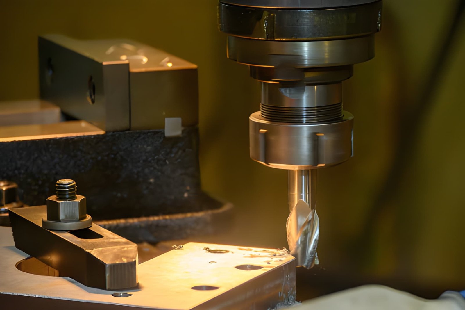
The image shows the side milling process on an NC milling machine using flat nose end mill tools (Source: iStock)
Side milling is a CNC machining process where material is removed using the side edges of a rotating cutter to generate vertical walls and controlled edge geometry.
“Side cutting” refers to engagement along the tool flank instead of the tool tip, which changes force direction, load distribution, and accuracy control.
- Material removal occurs along the tool diameter with controlled radial engagement.
- Radial forces push the tool away, causing a possible wall taper.
- Typical stepover ranges from 10% to 40% of the tool diameter.
- Tool overhang above 3-4× diameter increases deflection risk.
- Wall accuracy depends on rigidity, not only on toolpath precision.
- Finishing passes use low engagement to reduce cutting load.
How Side Milling Works
Side milling removes material along vertical surfaces using the cutter’s peripheral edges. It is used when wall geometry and edge accuracy must be controlled through side engagement instead of face cutting.
Cutting with the Tool Side Instead of the Tool End
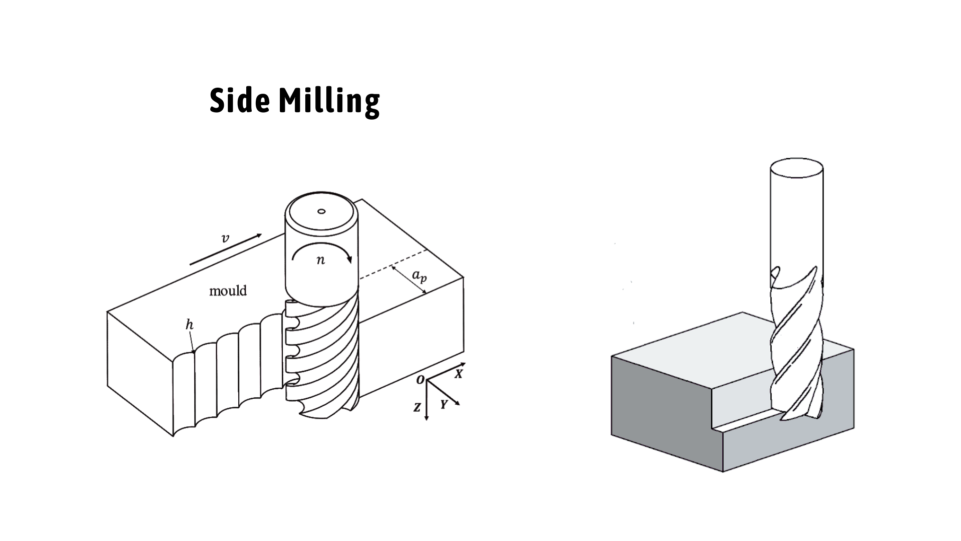
Technical illustration showing a side milling cutter engaged with a workpiece/mold, highlighting tool rotation and cutting action. (Source: engineeringtechnology.org)
Side milling cuts using the tool flank, not the tool tip. This change alters force direction and directly affects wall accuracy.
- Cutting occurs on the tool’s cylindrical edge, not the bottom face.
- Radial force pushes the tool away from the wall during engagement.
- Common in slot walls, shoulders, and bracket edges.
For example, in aluminum brackets, side milling defines mounting faces after drilling operations.
Radial Engagement Along Vertical Surfaces
The tool engages material along its diameter, creating continuous side load on both tool and workpiece.
- Stepover controls how much the tool contacts the wall per pass.
- Higher engagement increases deflection risk in long tools.
For example, in production environments, a 5 mm end mill with 40 mm overhang may produce wall taper in steel if engagement exceeds 30% diameter.
How Geometry Is Formed Through Side Passes
Wall geometry is built step by step through controlled machining passes rather than a single cut.
- Rough pass leaves extra stock for stability control.
- Semi-finishing corrects wall deviation and stabilizes the load.
- Finishing pass sets the final size within the tolerance range.
For instance, gearbox housings often use 0.2 to 0.5 mm finishing stock to maintain consistent bore and wall alignment.
Side Milling Parameters and Cutting Strategy
Side milling performance depends on how the cutting load is distributed through engagement, depth, feed, and toolpath choice. Each parameter affects tool deflection, wall accuracy, and surface stability during cutting.
Radial Engagement (Width of Cut) Control
Radial engagement defines how much of the tool side contacts the material. It directly changes cutting force and wall behavior.
- Low engagement keeps cutting forces stable.
- High engagement increases radial deflection risk.
- Uneven load causes wall taper and vibration.
Axial Depth and Stepdown Strategy
Axial depth controls how much material is removed along the tool length per pass. Stepdown planning balances load and stability.
- Shallow stepdown improves dimensional control.
- Deep cuts increase tool stress and vibration.
- Multi-step cuts reduce distortion on thin walls.
Feed Rate and Chip Load Optimization
Feed rate determines chip thickness and cutting energy. An incorrect chip load affects both finish and tool life.
- Low feed leads to rubbing and heat buildup.
- Excess feed increases vibration and deflection.
- Stable chip load improves surface consistency.
Climb Milling vs Conventional Milling
Cutting direction changes how the force interacts with the wall and tool. This influences stability and finish quality.
- Climb milling aligns cutting force with the feed direction, which improves surface finish and reduces tool deflection in finishing passes.
- Conventional milling increases cutting resistance.
- Climb preferred for controlled finishing passes.
A deeper breakdown of force direction and stability differences is covered in this climb milling vs conventional milling guide.
Toolpath Strategy (Single Pass vs Multi-pass Finishing)
Toolpath structure controls how the final geometry is formed. Stability improves when material removal is distributed.
- A single pass is only suitable for light finishing.
- Multi-pass reduces the load per cut stage.
- Final pass ensures dimensional correction and finish control.
Side Milling vs End Milling vs Face Milling
Comparison of side milling and other milling operations
These three milling operations differ in how the tool engages the material and how forces are distributed. Selection depends on geometry, required tolerance, and stability of the setup.
| Parameter | Side Milling | End Milling | Face Milling |
|---|---|---|---|
| Cutting Area | Tool peripheral edge | Tool tip + peripheral edge | Tool face |
| Primary Use | Vertical walls, shoulders, slots | Pockets, contours, 3D shapes | Flat surface finishing |
| Cutting Direction | Radial engagement | Mixed axial + radial | Axial engagement |
| Surface Type | Vertical walls | Internal + external profiles | Flat planes |
| Load Type | Continuous radial force | Variable combined load | Distributed axial load |
| Deflection Risk | High on long tools (>4×D overhang) | Medium, depending on engagement | Low on rigid setups |
| Typical Accuracy Range | ±0.02–0.05 mm (finishing, controlled setup) | ±0.01 to ±0.05 mm | ±0.01 to ±0.03 mm |
| Application | Slots, edges, shoulders | Die cavities, complex profiles | Stock leveling, finishing flats |
Notes on Performance Differences
- Side milling shows a higher deflection risk when the tool overhang exceeds 3-4× tool diameter due to radial load bending effects.
- End milling allows mixed engagement. This, as a result, improves flexibility in 2.5D and 3D geometry machining.
- Face milling distributes load across multiple inserts, reducing cutting force per edge and improving thermal stability.
What Affects Accuracy and Surface Quality in Side Milling
Side milling accuracy depends on how consistently the system handles radial cutting forces. Any instability in the tool, machine, or cutting conditions directly affects wall geometry and surface finish.
Tool Deflection and Dimensional Error on Walls
Tool deflection occurs when radial force bends the cutter away from the programmed contour. This changes the wall size and straightness along the full cutting height.
- An overhang above 3-4× tool diameter significantly increases the bending moment.
- Radial load creates measurable wall taper in finishing cuts.
- Small-diameter tools show higher elastic deflection under the same engagement.
Chatter and Vibration Under Side Load
Tool deflection occurs when radial force bends the cutter away from the programmed contour. This changes the wall size and straightness along the full cutting height.
- High radial engagement increases regenerative vibration risk.
- Thin walls amplify oscillation due to low structural stiffness.
- Spindle speed zones near natural frequency worsen surface marks.
Burr Formation and Edge Integrity
Burrs develop when material deforms instead of cleanly shearing at the tool exit. Side cutting increases this risk at edges and corners.
- Ductile materials show higher burr formation at high feed rates.
- Tool wear increases edge tearing and inconsistent burr size.
- Sharp cutting edges reduce plastic deformation at exit points.
Cutting Parameters and Load Stability
Cutting parameters control how stable chip formation remains during side engagement. Variations directly affect force consistency and surface finish.
- High feed increases radial load and wall deflection risk.
- Low feed causes rubbing and localized heat buildup.
- Uneven stepover creates fluctuating cutting forces along the wall height.
What Is a Side Milling Cutter and How It Works
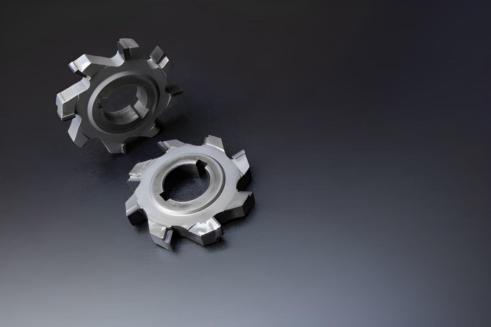
The image features side milling cutters with uniquely shaped teeth along the peripheral edge, optimized for better chip breaking. (Source: iStock)
Side milling performance depends mainly on cutter geometry, stiffness, and how efficiently chips leave the cutting zone. These factors control deflection, heat buildup, and surface consistency during side engagement.
Cutter Width and Engagement Capacity
Cutter diameter and effective width determine how much material is engaged along the wall. This directly affects load distribution and stability.
- A larger diameter improves rigidity under radial load.
- Narrow cutters increase flexibility but impose deflection risk.
- Engagement width controls cutting force per pass.
Tooth Geometry and Chip Evacuation
Tooth design affects chip formation, heat control, and cutting stability. Poor evacuation leads to recutting and surface damage.
- Helix angle influences chip flow direction and stability.
- Higher flute count improves finish but reduces chip space.
- Sharp edge geometry reduces cutting force in finishing passes.
Rigidity and Mounting Considerations
Cutter rigidity depends on the tool body strength and how it is held in the spindle. Weak mounting increases vibration and dimensional error.
- Short overhang improves bending resistance under radial load.
- Hydraulic and shrink-fit holders improve concentricity control.
- Runout above 0.01 to 0.02 mm increases uneven tool loading.
Design Guidelines for Side Milling (DFM Considerations)
Side milling performance depends heavily on part design. Proper design for side milling reduces tool deflection, improves wall accuracy, and lowers machining cost. Wall stiffness, load distribution, and allowance planning directly affect deflection, surface quality, and machining stability.
Maintain Wall Support to Reduce Deflection
Wall stability depends on how well the structure resists side-cutting forces. Thin or unsupported walls bend easily under radial load.
- Wall thickness below ~2–3 mm, especially at high aspect ratios, increases vibration risk in aluminum.
- Unsupported tall walls amplify tool pressure and taper risk.
- Adding ribs or nearby mass improves stiffness during cutting.
Allow Finishing Pass for Vertical Accuracy
A controlled finishing allowance helps reduce cutting load during final wall formation. It improves dimensional consistency and surface quality.
- Leave 0.2 - 0.5 mm stock for the final side milling pass.
- Roughing removes the bulk load before the precision cut.
- Final light pass reduces tool deflection influence.
Use Geometry That Reduces Side Load Concentration
Sharp transitions and abrupt changes increase localized stress during cutting. Smoother geometry reduces load spikes on the tool.
- Internal radii above 0.5× tool diameter improve stability.
- Avoid sudden thickness changes along the wall height.
- Gradual transitions reduce force concentration at corners.
When Side Milling Becomes Expensive
Side milling cost increases when cutting conditions force lower productivity, higher tool wear, and longer cycle time. Most cost drivers come from excessive engagement, deep geometry, and tight tolerance control.
High Radial Engagement Increasing Tool Wear
High radial engagement increases cutting force on the tool flank, which accelerates wear and reduces tool life. This directly raises tooling cost and tool change frequency.
- Engagement above 40% tool diameter increases the flank wear rate.
- Higher radial load causes faster edge chipping in steel machining.
- Tool life reduction leads to frequent offset recalibration.
Deep Features Requiring Multiple Passes
Deep side features require stepwise machining to maintain stability. Each additional pass increases machine time and tool load cycles.
- Depth beyond 3-4× tool diameter often needs staged cutting.
- Multiple roughing and semi-finishing passes increase cycle time.
- Long tool engagement increases vibration control requirements.
Tight Wall Tolerances Increasing Machining Time
Tight tolerances require low engagement finishing passes and repeated measurement checks. This reduces the feed rate and increases machining duration.
- Tolerance below ±0.02 mm requires reduced feed rates.
- Extra finishing passes are needed for wall correction.
- In-process inspection increases total machining time per part.
When NOT to Use Side Milling
Side milling is not suitable when geometry, stiffness, or tool access does not support stable radial cutting. In these cases, other machining methods provide better control over accuracy and cycle time.
Geometry Better Suited for Pocketing or Alternative Processes
Some geometries require bulk material removal instead of edge-based cutting. Side milling becomes inefficient and unstable in these cases.
- Large internal cavities are better handled by pocket milling.
- Deep open areas increase tool engagement length and vibration.
- 3D surfaces require contour or surface milling strategies.
- High material removal volumes increase cycle time significantly.
Parts Requiring High Rigidity and Minimal Deflection
Thin or flexible parts cannot resist radial cutting forces effectively. Side milling introduces deformation that affects final accuracy.
- Thin walls below 2 to 3 mm deflect under side load in aluminum.
- Long vertical features increase taper due to tool bending.
- Low-stiffness parts require face or supported machining methods.
- High precision surfaces need uniform axial engagement instead.
Situations with Limited Tool Access or Stability
Restricted access or poor fixturing reduces process stability. Side milling becomes unreliable when tool engagement cannot remain consistent.
- Deep internal features block the full side engagement path.
- Weak clamping increases vibration during continuous cutting.
- Unstable setups increase the risk of chatter and surface errors.
Typical Applications of Side Milling
Side milling is mainly used for forming vertical walls and edge-based geometry. It is preferred when dimensional control, straightness, and edge definition are required in CNC-machined parts.
Machining Vertical Walls and Shoulders
Side milling is commonly used to generate straight vertical surfaces with controlled height and alignment. It is applied after roughing to define the final geometry.
- Produces accurate vertical walls in prismatic parts.
- Controls the shoulder height between different features.
- Maintains wall straightness in stepped geometries.
Slots and Edge Features
Side milling is effective for narrow features where tool side engagement defines geometry. It is widely used for slotting and edge trimming.
- Used for keyways, slots, and grooves in metal parts.
- Controls slot width through tool diameter selection.
- Ensures clean edge definition after drilling or roughing.
Structural Parts Requiring Straight Edges
Structural components often require precise external boundaries for assembly and alignment. Side milling ensures consistent edge formation.
- Used in brackets, frames, and support structures.
- Maintains parallelism between opposite edges.
- Ensures proper fit during assembly operations.
Industry Applications of Side Milling
| Industry | Parts/Application |
|---|---|
| Aerospace | Structural brackets, support ribs, and lightweight frames |
| Automotive | Engine mounts, gearbox housings, chassis components |
| Mold & Die | Mold bases, guide slots, alignment features |
| General Engineering | Machine parts, fixtures, precision housings |
Key Takeaways About Side Milling
Side milling is used when vertical walls, shoulders, and edge features require controlled geometry and dimensional accuracy. It is effective for defining part boundaries, but performance depends heavily on rigidity, engagement control, and cutting stability.
It should be selected when:
- Vertical wall accuracy and straightness are required.
- Slots, shoulders, or edge features define the part function.
- Tool access allows stable side engagement without excessive overhang.
It becomes limited when:
- Thin walls or long overhangs increase deflection risk.
- Deep or complex geometry requires multiple unstable passes.
- Poor fixturing reduces control over radial cutting forces.
Engineering choices play a pivotal role in side milling results. Tool length, radial engagement, feed rate, and fixturing stability all shape the outcome. These factors decide whether walls stay accurate or develop taper, vibration, and surface issues. Careful planning at the design stage helps reduce machining risks and keeps results consistent in production.
Get Custom CNC Milling Parts with Precision Manufacturing at JLCCNC
At JLCCNC, we provide CNC milling services for complex geometries, tight tolerances, and production-ready parts. Our engineering team supports you with material selection, DFM feedback, and optimized machining strategies to reduce cost and improve part quality.
- Free DFM review before production.
- Engineering support for complex geometries.
- Wide material options, including metals and plastics.
- Surface finishing options for functional and cosmetic needs.
- Tight tolerance capability up to ±0.05 mm.
- Fast CNC milling with tight tolerance control.
Upload your CAD file and get an instant quote from JLCCNC starting at $1 with lead times as fast as 3 days.
FAQs About Side Milling
Q: What is side milling in CNC?
Side milling is a CNC machining process where material is removed using the side edges of a rotating cutter to create vertical walls, slots, and edge features with controlled geometry.
Q: What is a side milling cutter?
A side milling cutter is a rotating cutting tool that removes material using its peripheral edges. It is used to machine slots, shoulders, and vertical surfaces with defined accuracy.
Q: What’s the key difference between side milling and end milling?
Side milling mainly forms vertical walls using radial cutting, while end milling is used for pockets and general 3D features using both the tool tip and sides. Side milling focuses more on wall accuracy and edge control.
Q: When should side milling be used?
Side milling should be used when a part requires accurate vertical walls, straight edges, or slot features. It is selected when geometry depends on controlled side engagement rather than full face cutting.
Q: What causes wall taper in side milling?
Wall taper is mainly caused by tool deflection under radial cutting forces. Long tool overhang, high radial engagement, and low system rigidity increase bending, which shifts the tool away from the programmed path.
Q: How to reduce tool deflection in side milling?
Reduce tool overhang, lower radial engagement, and use multi-pass finishing. Increasing tool diameter, improving fixturing rigidity, and optimizing feed rate also help stabilize cutting forces.
Q: Is side milling more accurate than end milling?
Not necessarily. Side milling can achieve high wall accuracy in stable setups, but it is more sensitive to deflection. End milling is generally more stable for mixed geometries and shallow features.
Popular Articles
• Cutting with Precision: A Comprehensive Guide to CNC Water Jet Technology
• CNC Coolant Explained: Types, Maintenance & Safety
• Rake Angle in Machining: Machinists’ Guide to Perfect Cuts
• What Steps Are Taken To Minimize Waste In CNC Machining Processes?
• How EDM Wire Cutting Works: Complete Guide to Precision CNC Wire Cutting
Keep Learning
Chatter in Machining: Causes, Effects, and How to Reduce It
CNC milling operation producing visible chatter marks on an aluminum workpiece Quick Chatter Diagnosis Checklist Symptom Most Likely Cause First Action High-pitched squeal Regenerative chatter Change spindle speed ±15% Chatter only in deep pockets Excessive tool overhang Shorten tool Chatter on thin walls Low workpiece rigidity Improve fixturing Chatter after tool replacement Runout / holder issue Check tool holder Chatter only during finishing DOC too small / rubbing Increase feed or adjust speed It ......
What Is Tool Offset in CNC? Types, Setup & Best Practices
CNC tool offset setup with measurement overlay Key Takeaways CNC offsets connect programmed intent with actual cutter position. Length data guides Z-axis depth control. Radius data protects part size during contour milling. Geometry values define the cutter's measured baseline. Wear values support fine correction during production. Verified data lowers scrap risk before full machining. Good offset habits protect tools, fixtures, and parts. In the context of CNC machining, tool offset is the quiet setu......
Trochoidal Milling: Complete Guide to High-Efficiency CNC Machining
Key Takeaways Trochoidal milling combines circular cutter motion with continuous forward feed. The cutter normally engages 5 to 20% of its diameter instead of making a full-width cut. A smaller engagement angle limits force changes during slotting and pocket roughing. Low radial engagement often allows greater axial depths of cut than conventional slot milling. CAM software calculates the circular path automatically from the selected machining parameters. This strategy is widely applied to titanium, s......
What Is Die Casting? Process, Materials, and Applications
Key Takeaways Die casting is a metal casting process that forces molten metal into a reusable steel mold under high pressure, producing parts with tight tolerances and good surface finish at high volume. Aluminum die casting is the most common form by far, thanks to its combination of light weight, decent strength, and good corrosion resistance. The die casting process runs through mold preparation, injection, cooling, and ejection in a cycle that can repeat every few seconds to minutes depending on p......
First Angle vs Third Angle: Understanding Orthographic Projection Methods
Key Takeaways Orthographic projection is the system that lets a 3D part be represented through multiple 2D views, front, top, side, and so on. First angle projection and third angle projection are the two standard methods for arranging those views, and they place views in opposite positions relative to the object. First angle projection is the ISO standard used across most of Europe, India, China, Russia, and many other countries following ISO standards Third angle projection is the standard in the Un......
Micro EDM Machining: Capabilities, Materials, and Applications for Precision Components
Key Takeaways About Micro EDM Machining Only electrically conductive materials can be machined. Hole diameters can reach below 50 μm on specialized equipment. The process produces almost no mechanical cutting force, making it suitable for thin or delicate features. Surface integrity still requires attention because recast layers and heat-affected zones may remain after machining. Micro EDM is often combined with CNC machining, with milling producing the main geometry before EDM finishes critical micro......