Taper Turning in CNC and Lathe Machining: Methods, Angle Control, and Machining Stability
13 min
- What Is Taper Turning?
- Why Tapered Features Matter in Machined Parts
- Common Taper Forms in CNC Machining
- Common Taper Turning Methods on a Lathe
- Taper Attachments and CNC Motion Control
- Controlling Taper Angle and Dimensional Accuracy
- Machining Behavior During Taper Turning
- Common Problems in Taper Turning
- Choosing the Right Taper Turning Method
- CNC Applications of Taper Turning
- Conclusion About Taper Turning
- FAQ About Taper Turning
Key Takeaways About Taper Turning
- Taper turning creates a gradual diameter change along a rotating workpiece by moving the cutting tool at a controlled angle.
- Different taper turning methods suit different jobs. Compound slides often handle short tapers, while CNC interpolation and taper attachments improve repeatability on longer parts.
- Taper angle accuracy also depends on how dimensional tolerances are specified and inspected across the tapered surface.
- Long or slender parts may develop chatter, deflection, or dimensional drift during taper turning if support conditions are unstable.
- Tapered surfaces are widely used in tool holders, spindle interfaces, sealing features, and rotating assemblies because they improve alignment and contact behavior.
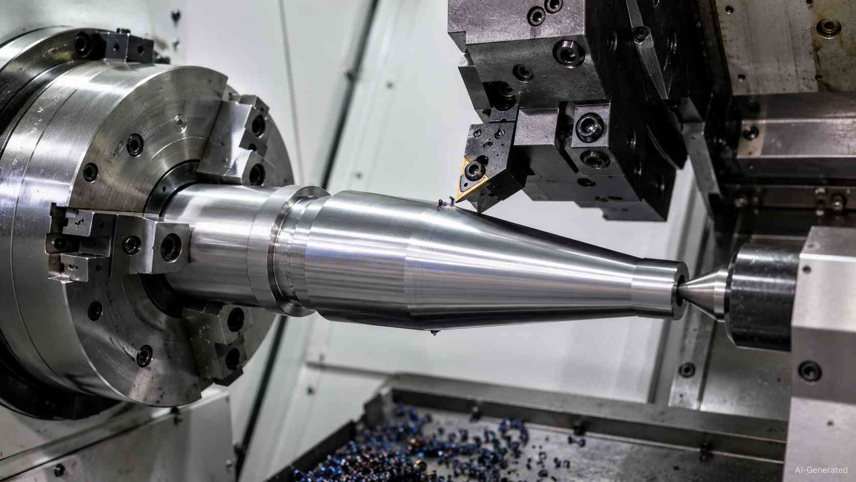
CNC lathe machining a tapered metal shaft
What Is Taper Turning?
Taper turning is a lathe machining operation that produces a gradual diameter change along the workpiece length by feeding the cutting tool at an angle to the rotational axis.
Because the cutting path continuously changes diameter, alignment, cutting stability, and dimensional verification become important throughout the operation.
How Taper Geometry Differs From Straight Turning
Unlike a cylindrical pass that keeps one constant size, tapered geometry changes from wider to narrower across a chosen distance. This sloped profile makes taper turning methods depend on tool direction, machine alignment, travel stability, and surface finish consistency rather than ordinary parallel cutting alone.
Why Tapered Features Matter in Machined Parts
Self-Centering and Alignment Behavior
As contact develops around the tapered surface, mating parts are guided toward a common axis. Toolholders, sleeves, and spindle interfaces often use this geometry for repeatable positioning rather than relying only on a flat shoulder.
Friction Locking and Torque Transmission
As soon as two conical faces are brought together by pressure, friction can transmit torque across the contact surface. In the process of taper turning, this makes taper angle selection important because it directly affects holding force, release behavior, and torque transmission.
Sealing and Concentricity Control
From that same wedging action, a tapered surface can generate more uniform contact pressure around a bore or shaft, and it helps fluid barriers and rotating parts remain coaxial during service.
Why Engineers Use Tapers Instead of Threads or Press Joints
When a part must locate accurately, transfer load, and come apart for service, a tapered joint can offer seating, holding force, and removal access without thread wear or interference damage.
Common Taper Forms in CNC Machining
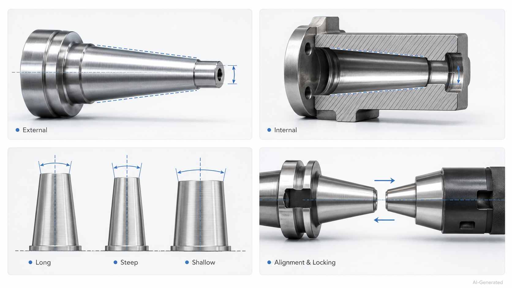
Common CNC taper forms and mating features
External Tapers on Shafts and Rotating Components
On outer diameters, the cone is cut around a shaft, pin, or rotating body. It gives the part a sloped landing that can guide couplings, pulleys, sleeves, or similar hardware during assembly.
Internal Tapers in Bores and Tool Interfaces
Inside a bore, the same geometry becomes a socket. That pocket must be reachable by boring tools or reamers, and its surface needs dependable contact when a mating shank enters.
Long, Steep, and Shallow Taper Geometry
Length and slope change the job's character. A long cone asks for travel control, a steep profile needs approach space, and a shallow profile demands patient measurement across the surface.
Functional Tapers for Alignment and Locking
In practice, taper turning is less about shape alone and more about selecting the right taper form for how the part must seat, release, carry load, or support accurate tool location.
Standard Machine Taper Forms
Some tapered interfaces follow standardized geometries rather than custom dimensions. Morse tapers are widely used in drills, toolholders, and spindle interfaces because the shallow angle creates self-holding contact under axial load. Steeper machine tapers are more suitable for applications that require quicker tool release and repeated tool changes.
In CNC machining, taper standards affect tooling compatibility, runout behavior, contact stability, and inspection requirements during production.
Common Taper Turning Methods on a Lathe
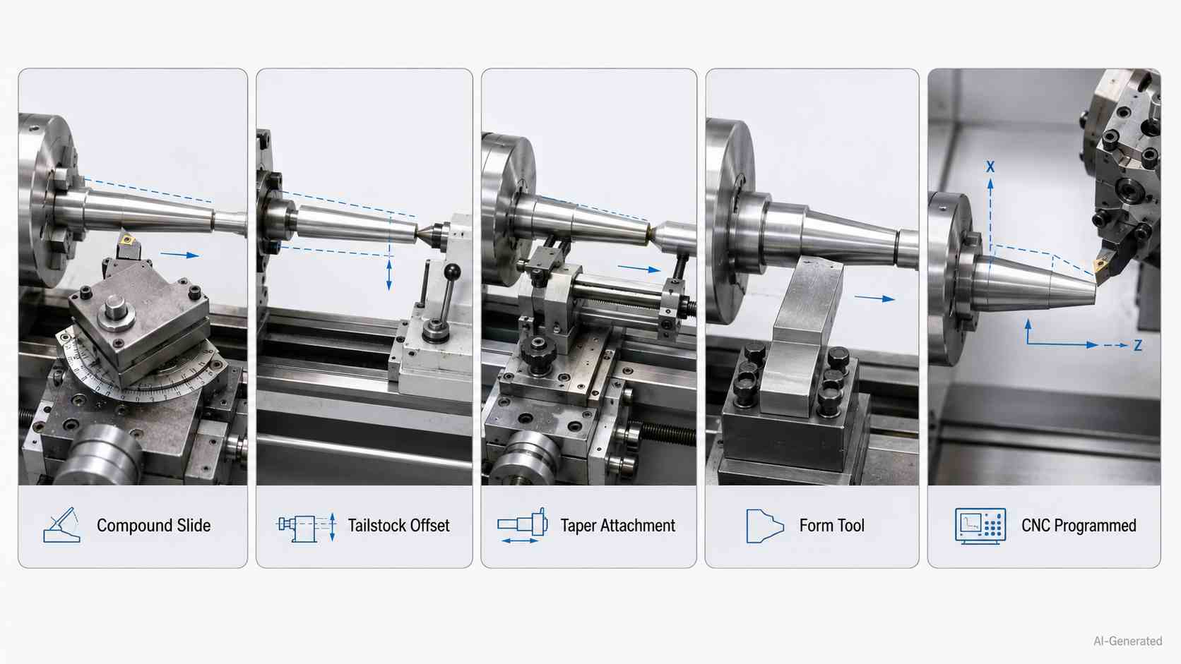
Common taper turning methods on a lathe
Compound Slide Method
When the compound slide is swung to the desired setting, the handwheel of the compound slide feeds the cutter down an inclined route. Undoubtedly, this option is appropriate for short profiles in which the operator wants to have direct control over the carriage.
Tailstock Offset Method
Next, the tailstock can be shifted sideways, placing the work axis slightly out of line. This approach is mainly used for long, shallow tapers on manual lathes, although offset setup and centerline alignment must be corrected carefully after machining.
Taper Attachment Method
A taper attachment for a lathe guides the carriage through a preset guide bar, which gives steadier travel than manual hand feeding when length or consistency is important.
Form Tool Method
For short and broad-angle shapes, a form tool carries the full profile on its cutting edge, which reduces travel needs but can raise cutting load during contact.
CNC Programmed Taper Turning
In the context of CNC work, taper turning comes from coordinated axis motion written into the program. This technique is particularly useful for repeat production where path control, cycle timing, and part-to-part consistency matter.
Taper Attachments and CNC Motion Control
Mechanical Taper Attachment Systems
A mechanical lathe taper attachment links carriage travel to an angled guide bar, which allows the cross slide to follow a measured path while axial feed carries the cut. That shared motion helps repeat angles across longer work without counting on handwheel judgment.
CNC Axis Interpolation and Servo Control
CNC systems command the X and Z axes simultaneously using linear interpolation. The servo loop ensures that each axis is in sync with the others, which allows the programmed taper profile to remain dimensionally consistent from part to part.
Tool Alignment and Centerline Accuracy
Once motion is handled, the cutting edge still has to meet the spindle centerline accurately. Poor height or holder alignment can shift the generated profile away from the intended geometry.
Tool Geometry and Insert Selection
The form of the insert, the nose radius, the rake, and the edge prep all play a role in determining how smoothly the insert follows the tapered surface during cutting. This assists the operator in achieving a balance between finish, tool pressure, and dimensional agreement throughout the machined face.
Controlling Taper Angle and Dimensional Accuracy
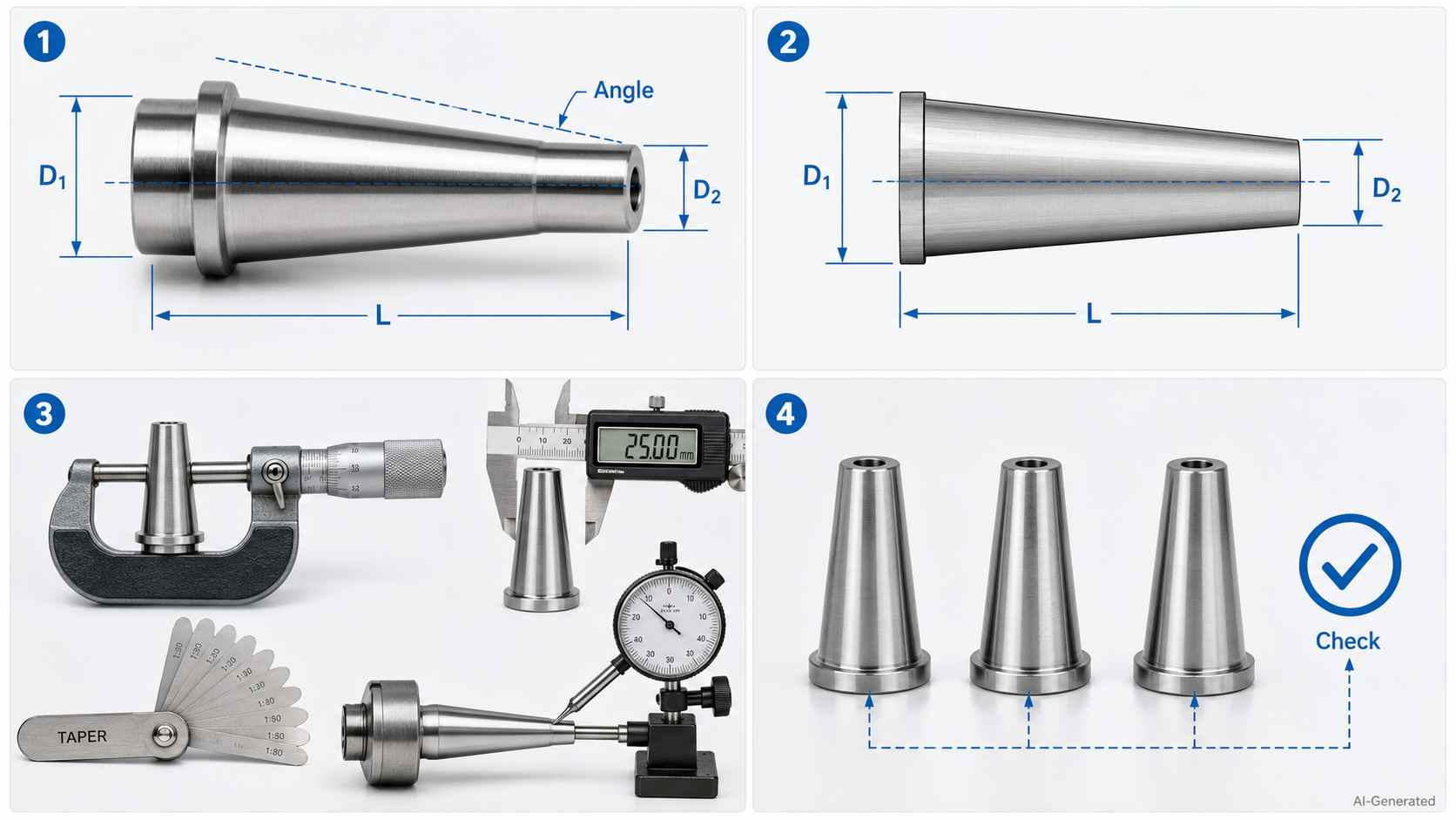
Taper angle measurement and inspection tools
Taper Ratio and Angle Calculation
Begin with the print. In taper turning, the taper angle defined on the drawing must be transferred accurately into the machine setup and axis movement. The tapering angle (specifically the taper half-angle) is calculated from the large diameter, small diameter, and taper length.
The taper half-angle can be calculated using:
tan(θ) = (D − d) / 2L
where D is the major diameter, d is the minor diameter, and L is the taper length.
Diameter-to-Length Relationships
Length gives the geometry its scale. The same diameter change over a shorter distance creates a steeper cone, but a longer distance creates a gentler one that needs closer travel monitoring.
Measuring and Inspecting Taper Geometry
After cutting, machinists check ends, the sloped surface, and contact pattern with micrometers, gauges, optical systems, or coordinate measurement equipment, based on the tolerance level.
Measuring and Verifying Taper Consistency
For production work, one accepted part is not enough. Readings are tracked across several pieces, and then, offsets or wear values are corrected before drift reaches the assembly stage.
Long or shallow tapers usually require closer control over setup alignment, support rigidity, and inspection method because small angular errors become more visible across extended surfaces.
JLCCNC reviews taper geometry, workholding stability, and machining accessibility before production begins, especially for parts that involve spindle fits, sealing contact, or precision rotating assemblies.

Precision CNC Machining Service
Professional manufacturing, fast turnaround, and quality assurance.
Machining Behavior During Taper Turning
Cutting Force Changes Along the Taper
As the cutter moves across a sloped profile, chip thickness and edge contact can vary end-to-end. The operator may notice a changing load and adjust feed or depth to maintain stable cutting conditions.
Tool Deflection and Long-Part Stability
That changing load can push a slender bar away from the edge, mainly when the overhang is high, which is why shorter projection and wider tool shanks help accuracy during taper turning.
Workpiece Support and Stability
As the job length grows, center pressure, chuck grip, and tail-end support become part of the cut. Proper support reduces workpiece deflection during machining.
Surface Finish Behavior on Tapered Surfaces
Surface finish depends on cutting stability, insert geometry, and consistent contact along the taper. The taper turning attachment method may be helpful in this regard since it guides travel mechanically, which decreases waviness during longer periods of manual lathe work.
Heat Generation and Chip Evacuation
Heat buildup and chip evacuation also affect taper accuracy during longer cuts. Good coolant aim with controlled chip flow keeps the edge from rubbing, the surface from tearing, and the size from drifting near the final pass.
Common Problems in Taper Turning
Incorrect Taper Angle and Geometry Errors
The incorrect slide setting, offset value, program number, or reference diameter is often the root cause of angle problems. After a single pass, the surface may appear acceptable visually; nevertheless, the gauge will reveal a cone that does not correspond to the drawing.
Chatter and Surface Irregularities
When vibration enters the cut, the slope shows ripples, bands, or dull patches. Taper turning becomes harder to hold within size limits as each pass copies some of that motion into the finish.
Dimensional Variation Along the Taper
Size drift can appear from heat, tool pressure, worn guides, or unstable clamping. It leaves one end closer to the target than the other and creates inconsistent readings along the taper length.
Poor Concentricity and Assembly Seating
If the work or tool runs off-center, the cone may pass a diameter check while still seating unevenly, which can create wobble, contact marks, or unreliable mating under load.
Tool Wear and Surface Finish Degradation
When the edge wears, the cutting pressure increases, the finish quality decreases, and taper turning methods that were previously able to maintain tolerance may need a tool replacement, offset correction, or changed cutting data before additional parts can be manufactured.
Choosing the Right Taper Turning Method
Short vs Long Taper Requirements
A short cone usually favors a compact setup with direct angle control. On the other hand, a longer one needs steadier guided travel across a greater distance. Taper length and tolerance usually determine whether manual adjustment is practical or whether guided motion control is required.
Manual Lathe vs CNC Turning Capability
Manual work is adequate for a one-off job where the operator can adjust by touch and measurement. However, CNC machining is better when the same profile must repeat across many parts with programmed axis movement and stable process control.
Prototype vs Production Machining
For prototypes, flexibility may matter more than cycle time. Nonetheless, production favors dependable setups, lower adjustment effort, and repeatable inspection results. That is where choosing among taper turning methods becomes a cost-and-quality decision.
CNC Applications of Taper Turning
Tool Holders and Machine Interfaces
Conical shanks are used by tool holders in order to locate cutting assemblies inside the spindle. This provides CNC machines with a reliable interface that allows for repeated tool changes, precise runout control, and consistent load transfer during milling or lathe operations.
Shafts, Spindles, and Rotating Components
It is possible for a tapered seat to direct pulleys, gears, collars, or bearing-related hardware into a coaxial position on shafts and spindle parts. This ensures that the assembly maintains a smooth rotation even when it is operating at high speeds and under load.
Tapered shaft sections are often machined together with bearing seats, shoulders, and threaded retention features.
Hydraulic and Sealing Features
Hydraulic ports and cone-seat features depend on intimate contact around a sloped face. Taper turning helps the machined surface control leakage paths under pressure.
Aerospace and Precision Mechanical Parts
Aerospace parts might demand certified CNC processes, strict quality checks, and dependable geometry. Meanwhile, a lathe taper attachment can still be important in support work where legacy equipment prepares tapered details before final inspection.
Conclusion About Taper Turning
Taper turning affects more than part shape. A small angle error can change contact position inside a spindle interface or reduce seating stability on a rotating assembly. Long tapers introduce another problem. Cutting force shifts gradually along the surface, so workholding and tool rigidity start to influence size consistency near the final passes.
Different taper turning methods solve different machining conditions. A compound slide may be enough for short manual work. Longer parts often depend on taper attachments or CNC axis interpolation to keep the surface tracking correctly across the full taper length.
Achieving precise concentricity and strict angle tolerances on tapered components requires rigorous process control. At JLCCNC, our advanced CNC turning centers utilize multi-axis linear interpolation and live inspection to ensure custom tapers mate perfectly without binding or alignment drift. Upload your CAD file today to receive instant DFM feedback and a production quote.
Precision CNC Machining Service
Professional manufacturing, fast turnaround, and quality assurance.
FAQ About Taper Turning
Q: What is taper turning in machining?
Taper turning in machining creates a cone-like surface on a rotating workpiece. That is where one end differs in diameter from the other across a set length.
Q: What is a taper attachment for a lathe?
A taper attachment is a guided lathe accessory that helps the cutting tool follow an angled path for longer tapered surfaces with less operator hand-feed variation.
Q: What is the most accurate taper turning method?
For repeat work, CNC axis control might be the preferred route. Yet, a well-set attachment can also give dependable manual-lathe results when the setup is handled with care.
Q: How does a taper attachment work on a lathe?
The attachment uses an angled guide to direct cross-slide movement as the carriage travels while enabling the tool to trace the required slope along the workpiece.
Q: What is the difference between internal and external taper turning?
External work shapes the outside of a part, and internal work machines a tapered bore. Each one needs tool access, gauge choice, and setup planning suited to its location.
Q: How is taper angle calculated in CNC turning?
The angle comes from the large diameter, small diameter, and tapered length. Once calculated, CNC code uses coordinated axis motion to follow that geometry.
Q: When is CNC taper turning preferred over manual methods?
CNC is commonly preferred when numerous parts need the same profile, tight size control, and repeatable inspection results without frequent manual adjustment.
Q: What is the difference between taper turning and straight turning?
Straight turning keeps a constant diameter along the workpiece length. Taper turning changes the diameter gradually by feeding the cutting tool at an angle relative to the rotational axis.
Keep Learning
Laser Engraving Aluminum: Marking Methods & Surface Effects
Key Takeaways Laser engraving usually removes base material to create a recess. Laser marking is a broader term that can describe a surface-color change or material removal, so the process name alone does not define the final result. On aluminum, alloy and surface finish affect marking contrast. A light mark on dark anodized aluminum is a common design target, but the actual appearance depends on the finish and laser process. JLCCNC laser marking produces a recessed area 0.03–0.1 mm deep. The result i......
CNC Cutting Fluid: Types, Functions, Applications, and Selection Guide
Key Takeaways Cutting fluid in machining performs four functions simultaneously: cooling the tool and workpiece, lubricating the tool-chip interface to reduce friction, carrying chips away from the cut zone, and protecting machined surfaces from corrosion between operations. Different machining operations need different fluid priorities: high-speed aluminum milling may need adhesion control and chip evacuation, threading and tapping need strong lubrication, and grinding requires both cooling and fine ......
Blind Hole Machining Guide: What Is a Blind Hole, Types of Holes, and Tapping Tips
What Is a Blind Hole? Types of Holes and CNC Hole Machining Explained In CNC machining, few operations challenge process control and tool stability as much as blind hole machining. A blind hole is a hole that terminates at a defined internal depth rather than breaking through the opposite surface. Because the cavity is enclosed at the bottom, chip evacuation, thermal behavior, tool wear, and dimensional accuracy become far more difficult to manage compared to through-hole machining. These constraints ......
Rake Angle in Machining: Machinists’ Guide to Perfect Cuts
What is Rake Angle? (minaprem) If you've ever stood in front of a CNC machine or a manual lathe, you know that the cutting tool's geometry isn't just some arbitrary design. Every angle, edge, and surface has a job to do, and one of the most important of those is the rake angle. We've been running machines long enough to know that rake angle can make or break your surface finish, tool life, and machining efficiency. In this guide, we're going to walk you through what rake angle is, how it works, and ho......
Sheet Metal vs CNC Machining: A Guide to Choosing the Right Method for Your Metal Parts
Quick Answer: Choose sheet metal for uniform-thickness enclosures, panels, and formed brackets when bends and production volume support lower unit cost. Choose CNC machining for variable wall thickness, precision bores, tight feature relationships, and complex 3D geometry. Use a hybrid design when a formed structure needs precision-machined interfaces. A quote comes back for a bracket, and it's priced as a CNC part — machined from solid aluminum, a few hours of spindle time, a per-part cost that makes......
What Steps Are Taken To Minimize Waste In CNC Machining Processes?
How to Reduce Waste in CNC Machining: 5 Practical Strategies Quick Answer: CNC machining waste is reduced mainly through DFM, near-net stock, efficient toolpaths, preventive tool maintenance, and alloy-segregated recycling. The biggest gains usually come before cutting: reduce unnecessary material removal and prevent scrap or rework. Every CNC-machined part starts as more material than it ends up being. A pocket gets milled out, a profile gets cut away, a boss gets faced down to size — and all of that......