What Is Profile Milling in CNC? Process, Methods, and Applications
13 min
- What Is Profile Milling in CNC Machining
- How Profile Milling Generates Part Geometry
- Why Profile Milling Is Difficult to Control (Accuracy and Stability)
- Profile Milling Strategies and Cutting Parameters
- When Should You Use Profile Milling?
- Profile Milling vs Other Milling Operations
- Design Guidelines for Better Profile Milling (DFM)
- When Profile Milling Becomes Expensive
- When Not to Use Profile Milling
- Typical Applications of Profile Milling
- Key Takeaways About CNC Profile Milling
- FAQs About Profile Milling
Profile milling is a CNC machining process that cuts along a programmed contour to define the outer or inner edges of a part. It is commonly used for shaping boundaries, improving edge accuracy, and finishing part geometry in 2D or 2.5D machining.
In practice, profile milling requires strong control over tool deflection, cutting forces, and workpiece stability. Any small deviation in toolpath or setup can affect dimensional accuracy and surface quality, especially on thin walls or long contour paths. Engineers often focus on rigidity, tool selection, and cutting strategy to maintain stable results.
This article explains how profile milling works, why accuracy challenges occur, and how machining stability can be improved in actual production environments.
What Is Profile Milling in CNC Machining
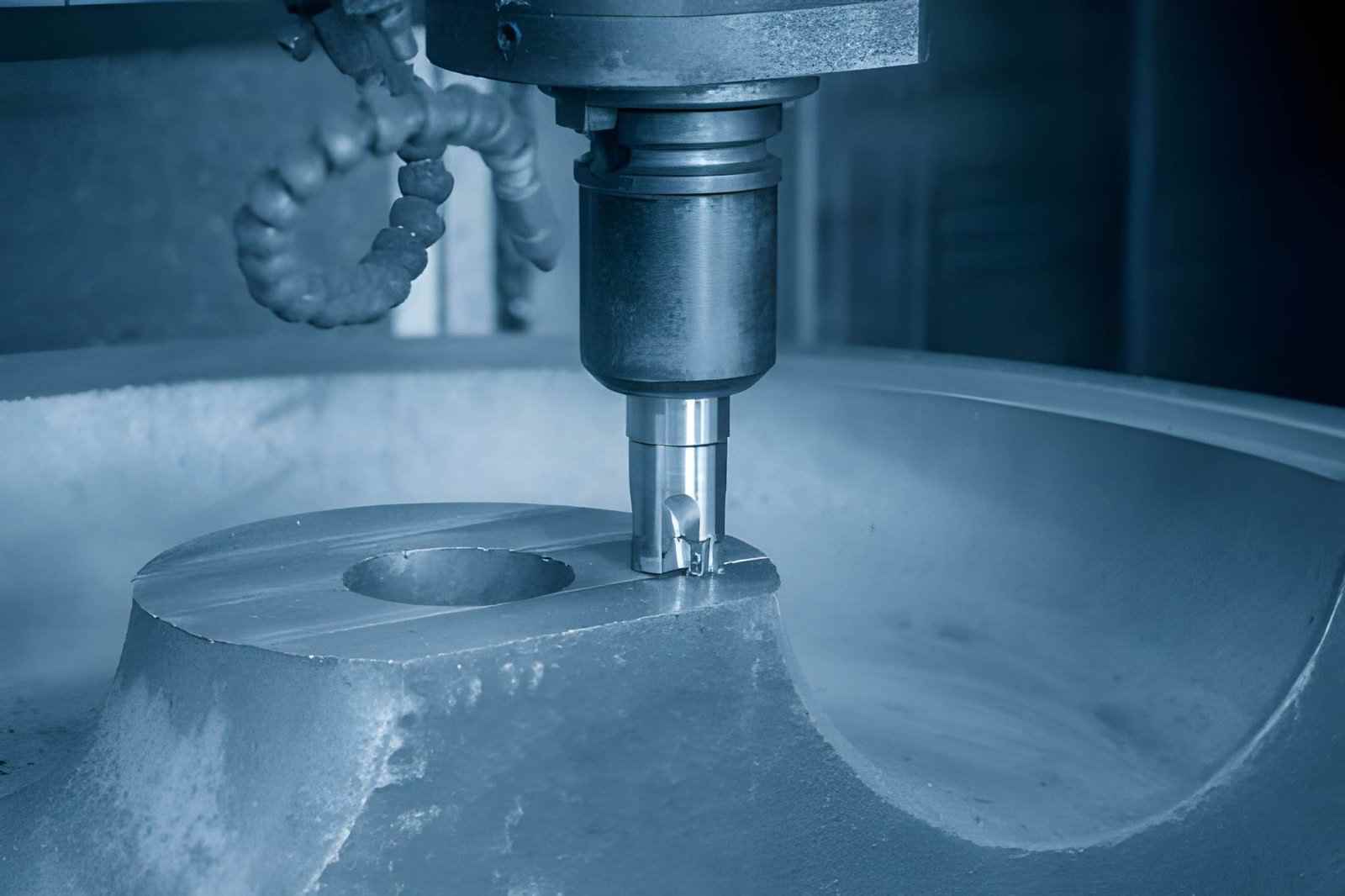
The image shows a CNC cutter performing profile milling on the top surface of a workpiece. (iStock)
Profile milling is a CNC machining process where the cutter moves along a defined contour to create or finish the edge shape of a part.
- The cutter follows a programmed edge path in X and Y directions.
- The tool removes material along the side of the workpiece.
- In typical 3-axis setups, the spindle remains vertical during cutting.
- The process defines the outer and inner part boundaries.
- It is used to machine specific part types like plates, brackets, housings, frames, and covers.
How Profile Milling Generates Part Geometry
Profile milling creates part geometry by moving the cutter along a defined contour and removing material from the edges of the workpiece. Instead of clearing full pockets, it focuses on shaping boundaries through controlled toolpath motion.
Contour-Following Motion Instead of Bulk Material Removal
Profile milling shapes the part by following its outer or inner contour instead of removing large volumes of material.
- The tool moves along a programmed edge path in X and Y directions.
- Material removal is concentrated at the part boundary, where geometry is progressively defined.
- Cutting focuses on shape definition instead of full-area clearing.
- Toolpath accuracy directly controls final geometry quality.
Radial Engagement Along External Edges
The cutter engages the material from the side, which defines the edge profile of the part.
- The tool contacts the workpiece along its radial cutting edge.
- Engagement depth is controlled to manage cutting load.
- External edges are formed by a steady side cutting motion.
- Tool deflection directly affects edge accuracy.
How Geometry Is Built Through Sequential Passes
Final shape is achieved through multiple controlled passes rather than a single cut.
- Rough passes remove excess material close to the final shape.
- Semi-finishing improves edge accuracy and stability.
- Finishing pass defines the final dimension and surface quality.
- Each pass reduces the stock gradually to control stress and deflection.
Why Profile Milling Is Difficult to Control (Accuracy and Stability)
Profile milling is difficult to control because cutting forces remain active along the contour, and those forces change with geometry, direction, and engagement length. This makes the process sensitive to small variations in tool rigidity, machine response, and part stiffness.
Tool Deflection Under Continuous Edge Engagement
Side cutting forces act continuously on the tool, which leads to elastic bending and dimensional deviation.
- Radial cutting force pushes the tool away from the programmed contour.
- Long tool overhang increases deflection, especially beyond 3× tool diameter.
- Increased depth of cut raises side load and causes taper on vertical walls.
Machine Dynamics During Direction Changes
Accuracy reduces during contour transitions due to machine response limits and interpolation behavior.
- Axis reversal introduces servo lag in sharp corners and tight radii.
- High feed rates reduce contour fidelity during directional changes.
- Circular interpolation errors appear on complex curved geometries.
Load Variation and Geometry-Induced Instability
Cutting load changes continuously based on geometry, which affects stability during the same operation.
- Thin walls increase vibration due to low structural stiffness.
- Sharp corners create sudden load spikes on tool engagement.
- Variable stock conditions lead to inconsistent cutting forces across passes.
Profile Milling Strategies and Cutting Parameters
Profile milling performance depends on how the cutting direction, engagement, depth, and toolpath are controlled. Small changes in these settings directly affect deflection, surface finish, and dimensional accuracy.
Climb Milling vs Conventional Milling
Cutting direction changes how forces act on the tool and workpiece.
- Climb milling can reduce tool deflection by pulling the cutter into the material, although the effect depends on machine backlash, rigidity, and material.
- It improves surface finish due to lower friction and stable chip load.
- Conventional milling increases stability in roughing with interrupted or hard surfaces.
A more detailed comparison of climb and conventional milling explains how each approach changes force direction and chip formation.
Comparison Table
| Parameter | Climb Milling | Conventional Milling |
|---|---|---|
| Cutting Force Direction | With feed direction, lower friction zone entry | Against the feed direction, higher rubbing at the entry |
| Tool Deflection | Lower, typically a 10 - 30% reduction in radial load | Higher due to the pushing effect on the tool edge |
| Surface Finish (Ra) | ~0.8 - 3.2 µm in finishing passes | ~1.6 - 6.3 µm depending on setup |
| Chip Thickness Behavior | Starts thick and reduces, stable cutting | Starts thin and increases, more rubbing |
| Tool Wear Rate | Lower in stable CNC setups | Higher in abrasive or interrupted cuts |
| Best Application | Finishing, contour accuracy, and thin walls | Roughing, scale removal, unstable stock |
Radial Engagement and Stepover Control
Stepover controls how much of the tool engages the material in each pass.
- Low stepover improves edge accuracy and reduces cutting force.
- High stepover increases material removal rate but raises tool deflection risk.
- Typical finishing stepover ranges from 5% to 15% of the tool diameter.
Depth of Cut and Pass Strategy
Material removal is controlled through staged cutting to maintain stability.
- Roughing uses a higher depth of cut to remove bulk material efficiently.
- Finishing uses shallow cuts for dimensional accuracy and surface quality.
- Leaving 0.2 to 0.5 mm stock improves final contour consistency.
Tool Selection and Toolpath Optimization
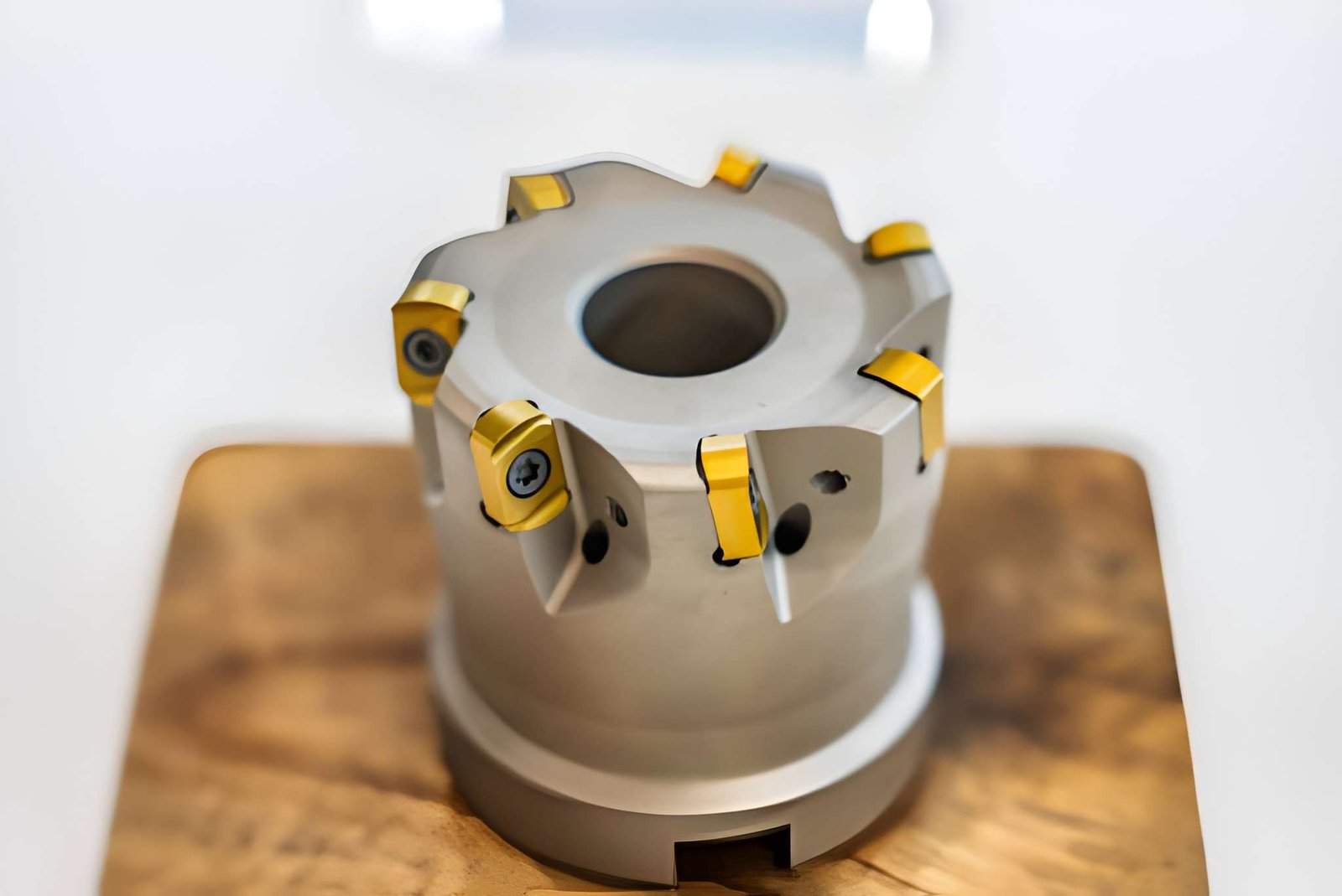
The image shows a profile milling cutter used in CNC machining. The tool includes carbide cutting edges and inserts. (iStock)
Tool and path design directly influence vibration and edge quality.
- Sharp cutting tools reduce burr formation and cutting force variation.
- Short tool overhang improves rigidity and reduces deflection.
- Smooth toolpath transitions reduce vibration during direction changes.
- Optimized CAM paths improve consistency on curved and complex profiles.
When Should You Use Profile Milling?
Profile milling is most effective when part geometry and functional requirements depend on accurate contour definition rather than bulk material removal.
- When external or internal edge geometry defines part function or fit
- When finishing operations require consistent and controlled external contours
- When tight boundary accuracy is required on 2D or 2.5D features
Profile milling is best for edge shaping, while pocket milling removes internal material and face milling prepares flat surfaces.
Profile Milling vs Other Milling Operations
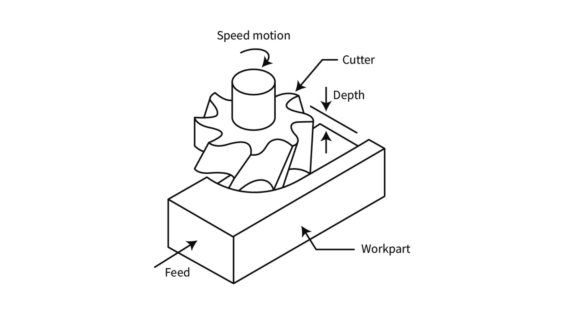
The image shows an illustration of the face milling process in CNC machining. (Source: spee3d.com)
Although profile milling, pocket milling, and face milling all remove material with rotating cutters, they are used for different part features. Each process has different cutting behavior, load distribution, and accuracy control requirements.
| Parameter | Profile Milling | Pocket Milling | Face Milling |
|---|---|---|---|
| Primary Purpose | Edge shaping of part geometry | Internal cavity material removal | Flat surface finishing |
| Cutting Area | Along the outer or inner boundary | Enclosed internal region | Large flat surface area |
| Tool Engagement | Side cutting, partial engagement | Full engagement in multiple directions | Face of cutter, broad contact |
| Material Removal Rate | Medium | High | Very high |
| Accuracy Control | Sensitive to deflection and vibration | Stable after roughing passes | High stability on rigid setups |
| Typical Tolerance Range | ±0.02 to ±0.10 mm | ±0.05 to ±0.20 mm | ±0.02 to ±0.05 mm |
| Common Applications | Brackets, housings, frames | Pockets, cavities, molds | Plate surfacing, stock leveling |
Design Guidelines for Better Profile Milling (DFM)
Design choices directly control tool stability, deflection, and surface quality in profile milling. Poor geometry increases cutting load variation and leads to vibration, while stable designs keep machining predictable.
Avoid Sharp Internal Corners and Tight Radii
Sharp corners force sudden tool direction changes, which increase load spikes and tool deflection.
- Internal radius should be at least 0.5× tool diameter, for example, 5 mm for a 10 mm end mill.
- Larger radii reduce servo load during direction change and improve contour smoothness.
- Zero-radius corners cause dwell marks and increase tool wear at entry points.
- Matching standard cutter sizes reduces interpolation error and tool stress.
Maintain Consistent Wall Thickness for Stability
Uneven wall thickness changes stiffness, which directly affects cutting stability during profiling.
- Keep variation within 20 to 30% to avoid stiffness imbalance across sections.
- Thin walls below 2 mm in aluminum increase chatter risk under side load.
- Sudden thick-to-thin transitions create localized deflection zones.
- Uniform stiffness improves dimensional repeatability in finishing passes.
Add Finishing Allowance on Critical Edges
Controlled stock removal improves accuracy and reduces final cutting load.
- Leave 0.2 to 0.5 mm stock per side for finishing operations.
- Roughing removes bulk material before the final contour pass.
- Finishing pass reduces tool deflection due to lower engagement depth.
- Consistent allowance improves dimensional control across batches.
Reduce Long Unsupported Edge Features
Long unsupported edges reduce rigidity and increase vibration under side cutting forces.
- Edge lengths above 3 - 5× wall height increase deflection risk in steel and aluminum.
- Add ribs or support walls to improve local stiffness during machining.
- Segment long profiles to reduce continuous tool engagement length.
When Profile Milling Becomes Expensive
Profile milling cost increases when geometry forces slow cutting, extra passes, and frequent stability control. Most cost growth comes from reduced material removal rate and longer spindle time per feature.
Long Contours Increasing Cycle Time
Long toolpaths increase machining time because the cutter stays engaged along the full boundary.
- A 300 - 500 mm contour can take 2 - 4× longer than pocketing the same area.
- Feed rate must drop from ~1500 mm/min to ~600 to 900 mm/min on thin sections.
- Direction changes add deceleration and re-acceleration time at every corner.
- Long continuous paths increase tool wear, requiring earlier tool replacement.
Tight Tolerances Requiring Additional Finishing Passes
Tight dimensional limits force extra machining stages and inspection loops.
- Finishing stock is typically reduced from 0.5 mm to 0.2 mm per side for accuracy control.
- Two-pass finishing (semi + final) increases cycle time by 20 to 40%.
- Feed rate is often reduced to 300 to 800 mm/min for ±0.01 to 0.02 mm tolerance work in well-controlled machining setups.
- In-process measurement adds 5 to 15 minutes per setup in precision jobs.
Thin Walls Forcing Conservative Cutting Parameters
Low-stiffness parts require reduced cutting load to prevent deflection and scrap.
- Wall thickness below 2 to 3 mm in aluminum requires a depth of cut under 0.5 mm.
- Tool engagement is typically reduced to 10–20% stepover to control vibration.
- Multiple light passes replace single efficient roughing cuts.
When Not to Use Profile Milling
Profile milling is not suitable when geometry, rigidity, or tool access limit stable side cutting. In these cases, other machining strategies provide better control over accuracy, cycle time, and surface quality.
Geometry Better Suited for Pocketing or Alternative Processes
Some parts require bulk material removal instead of edge-based cutting.
- Large internal cavities are faster with pocket milling than contour passes.
- Deep slots with wide areas create unstable long tool engagement in profile milling.
- 3D surfaces require contour or surface milling instead of edge following.
- High material removal volume increases cycle time in profile-only strategies.
Parts Requiring High Rigidity and Minimal Deflection
Thin or flexible parts lose accuracy during side cutting due to tool pressure.
- Thin walls below 2 - 3 mm deflect under radial cutting load.
- Long vertical walls increase tool bending and taper risk.
- Low-stiffness parts require face or support-based machining instead of edge profiling.
- High precision surfaces need stable full-face engagement instead of side load.
Situations With Limited Tool Access or Stability
Restricted geometry or setup conditions reduce profile milling effectiveness.
- Deep internal features block direct toolpath access along edges.
- Complex fixturing reduces tool clearance and increases collision risk.
- Poor clamping stability increases vibration during continuous contour cuts.
Typical Applications of Profile Milling
Profile milling is used for parts where the main requirement is accurate external or internal edge geometry. It is applied when the contour defines the function, fit, or assembly alignment of the component.
External Contours in Structural Components
Structural parts often depend on accurate outer geometry for fit and alignment in assemblies.
- Machine frames and load-bearing parts require controlled outer profiles.
- External contours maintain positional accuracy with mating components.
- Large flat structures use profile milling after rough stock removal.
- Consistent edge geometry supports assembly alignment and stability.
Plates, Brackets, and Enclosures
Flat and medium-thickness components rely on profile milling for final shape definition.
- Brackets require accurate edge profiles for mounting alignment.
- Plates are cut to final dimensions after face milling and drilling.
- Enclosures depend on clean outer boundaries for assembly fit.
- Profile milling ensures consistent part outlines in batch production.
Parts Requiring Clean Edge Definition
Some components need sharp and accurate edges for functional or visual requirements.
- Gasket seating surfaces require smooth and controlled edges.
- Covers and housings need precise boundary geometry for sealing.
- Cosmetic parts require consistent edge quality after machining.
- Final contour passes remove burrs and define sharp part boundaries.
Key Takeaways About CNC Profile Milling
Profile milling is effective when the part function depends on accurate edge geometry and controlled contour cutting. It delivers good dimensional control, but stability depends heavily on tool rigidity, setup design, and material behavior during side engagement.
- Profile milling works best for parts with defined external or internal contours, not bulk material removal.
- Accuracy depends on controlling tool deflection, especially on long edges and thin walls.
- Cycle time increases when contours are long, tolerances are tight, or finishing passes are required.
- Process stability improves when designers avoid thin walls, sharp corners, and unsupported edge lengths.
- It becomes inefficient when geometry requires high stock removal or limited tool access.
JLCCNC provides CNC milling services with optimized toolpaths, rigid fixturing, and strict tolerance control.
With prices starting from $1 and lead times as fast as 3 days, we help engineers produce accurate profile parts for both prototyping and production.
Upload your CAD file to get an instant quote.
FAQs About Profile Milling
Q: What is profile milling, and how does it work?
Profile milling is a CNC machining process where the cutter moves along a programmed contour to form or finish the edge shape of a part. It mainly applies to outer and inner boundaries rather than bulk material removal.
Q: What is the difference between profile milling and contouring?
Profiling focuses on cutting along part edges to define the final geometry. Contouring involves following more complex toolpaths that may include multiple surfaces, varying depths, or multi-axis movement. Profiling stays mostly 2D, while contouring can extend into 3D machining.
Q: Why is profile milling accuracy hard to control?
Accuracy becomes difficult because the tool stays in continuous edge contact, which increases deflection and vibration. Direction changes also affect machine response, and thin walls amplify movement under cutting forces, leading to dimensional variation.
Popular Articles
• Cutting with Precision: A Comprehensive Guide to CNC Water Jet Technology
• CNC Coolant Explained: Types, Maintenance & Safety
• Rake Angle in Machining: Machinists’ Guide to Perfect Cuts
• What Steps Are Taken To Minimize Waste In CNC Machining Processes?
• How EDM Wire Cutting Works: Complete Guide to Precision CNC Wire Cutting
Keep Learning
Chatter in Machining: Causes, Effects, and How to Reduce It
CNC milling operation producing visible chatter marks on an aluminum workpiece Quick Chatter Diagnosis Checklist Symptom Most Likely Cause First Action High-pitched squeal Regenerative chatter Change spindle speed ±15% Chatter only in deep pockets Excessive tool overhang Shorten tool Chatter on thin walls Low workpiece rigidity Improve fixturing Chatter after tool replacement Runout / holder issue Check tool holder Chatter only during finishing DOC too small / rubbing Increase feed or adjust speed It ......
What Is Tool Offset in CNC? Types, Setup & Best Practices
CNC tool offset setup with measurement overlay Key Takeaways CNC offsets connect programmed intent with actual cutter position. Length data guides Z-axis depth control. Radius data protects part size during contour milling. Geometry values define the cutter's measured baseline. Wear values support fine correction during production. Verified data lowers scrap risk before full machining. Good offset habits protect tools, fixtures, and parts. In the context of CNC machining, tool offset is the quiet setu......
Trochoidal Milling: Complete Guide to High-Efficiency CNC Machining
Key Takeaways Trochoidal milling combines circular cutter motion with continuous forward feed. The cutter normally engages 5 to 20% of its diameter instead of making a full-width cut. A smaller engagement angle limits force changes during slotting and pocket roughing. Low radial engagement often allows greater axial depths of cut than conventional slot milling. CAM software calculates the circular path automatically from the selected machining parameters. This strategy is widely applied to titanium, s......
What Is Die Casting? Process, Materials, and Applications
Key Takeaways Die casting is a metal casting process that forces molten metal into a reusable steel mold under high pressure, producing parts with tight tolerances and good surface finish at high volume. Aluminum die casting is the most common form by far, thanks to its combination of light weight, decent strength, and good corrosion resistance. The die casting process runs through mold preparation, injection, cooling, and ejection in a cycle that can repeat every few seconds to minutes depending on p......
First Angle vs Third Angle: Understanding Orthographic Projection Methods
Key Takeaways Orthographic projection is the system that lets a 3D part be represented through multiple 2D views, front, top, side, and so on. First angle projection and third angle projection are the two standard methods for arranging those views, and they place views in opposite positions relative to the object. First angle projection is the ISO standard used across most of Europe, India, China, Russia, and many other countries following ISO standards Third angle projection is the standard in the Un......
Micro EDM Machining: Capabilities, Materials, and Applications for Precision Components
Key Takeaways About Micro EDM Machining Only electrically conductive materials can be machined. Hole diameters can reach below 50 μm on specialized equipment. The process produces almost no mechanical cutting force, making it suitable for thin or delicate features. Surface integrity still requires attention because recast layers and heat-affected zones may remain after machining. Micro EDM is often combined with CNC machining, with milling producing the main geometry before EDM finishes critical micro......