Involute Gears: Profile Design, Drawing, and CNC Manufacturing
22 min
- What Is an Involute Gear?
- How to Design an Involute Gear for CNC Manufacturing
- Key Parameters in Involute Gear Design
- How to Draw an Involute Gear Profile
- Involute Gear Profile Equations and Calculation
- Advantages of Involute Gears
- Manufacturing Methods for Involute Gears
- Machining Challenges in Involute Gear Production
- Materials and Heat Treatment for Involute Gears
- Applications of Involute Gears in CNC Manufacturing
- Conclusion About Involute Gears
- FAQ About Involute Gears
Key Takeaways About Involute Gears
- Involute tooth geometry allows gears to stay in contact through a controlled rolling path.
- Small shaft position changes usually have less effect on gear engagement.
- Most industrial spur and helical gears use involute profiles because machining methods are well established.
- Gear drawings are built from values such as module, pressure angle, pitch diameter, and tooth count.
- Tooth shape accuracy affects backlash, contact area, and running behavior after assembly.
- Gear manufacturing often includes cutting, heat treatment, and finishing stages.
- Surface condition and tooth profile quality influence wear and operating noise.
- Profile checks are commonly used because diameter measurements alone cannot verify gear performance.
- Gear design decisions affect tooling selection and production difficulty.
- Stable machining conditions help maintain tooth consistency across multiple parts.
Gear parts rarely fail because of outside diameter or tooth count alone. Most problems appear after assembly. Noise, uneven contact, poor fit, and early wear often result from small changes in tooth shape that are difficult to detect during a basic inspection.
Involute gears are the most widely used gear type in modern machinery because their involute gear profile maintains stable tooth engagement during rotation. Engineers use involute geometry in spur and helical gears for gearboxes, robotics, CNC systems, and industrial power transmission. Understanding how to design an involute gear involves profile generation, gear equations, CAD drawing, and suitable manufacturing methods.
From a manufacturing side, producing an involute gear involves more than cutting repeated teeth around a part. Tooth spacing, profile shape, cutting method, heat treatment, and finishing steps all affect how the gear behaves later in operation.
This article explains involute gears from a CNC machining view, including profile design, CAD generation, machining methods, and production details that influence final gear quality.
What Is an Involute Gear?
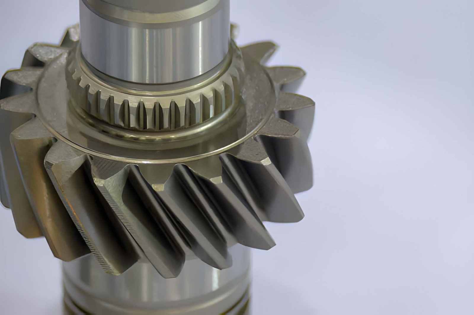
The image shows a close-up view of transmission gear spare parts with visible gear teeth and metal surfaces. (iStock)
An involute gear uses a tooth profile generated from a curve that gradually rolls outward from a base circle, creating a tooth shape that keeps gear contact stable during rotation.
Modern CAD systems usually generate involute profiles parametrically from module, pressure angle, tooth count, and pitch diameter.
These dimensions control how teeth contact each other after assembly and affect backlash, load distribution, and running behavior.
Why Involute Gears Became the Industry Standard
Involute gears became common because they are easier to produce repeatedly with standard manufacturing methods. Gear hobbing, shaping, grinding, and CNC machining can create involute teeth without changing the cutter for every gear size.
Assembly variation also becomes easier to manage with involute profiles. Small center distance changes between shafts usually create less effect on gear contact compared with other profile types. In production environments, this helps maintain more stable gear performance across multiple parts and assemblies.
Involute Gears vs Non-Involute Gear Profiles
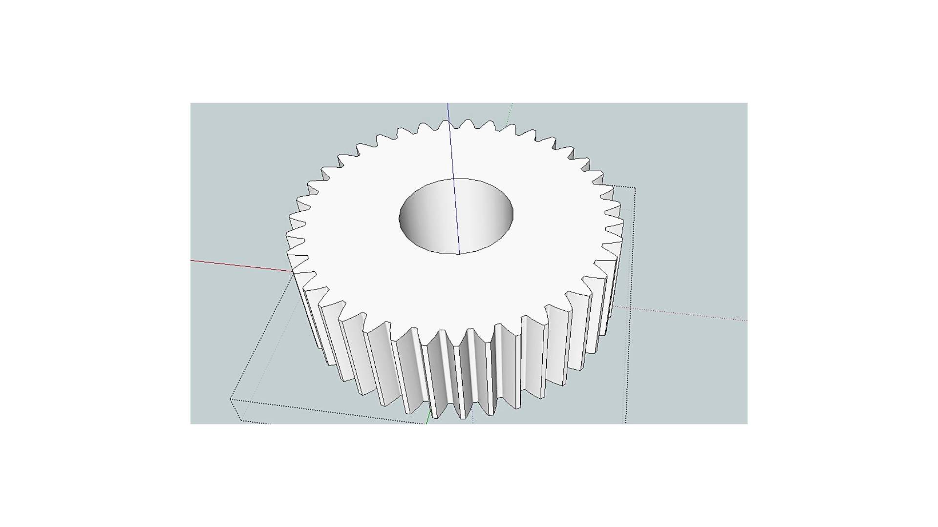
The image shows an illustration of an involute gear tooth profile geometry. (Capolight Electronics Projects)
Different gear profiles transfer motion differently because tooth contact changes along the rotation path. Involute profiles prioritize manufacturing consistency and stable meshing behavior, while other profiles are often selected for specific operating conditions.
| Feature | Involute Gear | Non-Involute Gear Profiles |
|---|---|---|
| Tooth engagement during rotation | Tooth contact moves smoothly across the flank | Contact behavior changes based on profile shape |
| Shaft position variation | Small center distance variation usually causes fewer meshing issues | Small shaft position changes affect contact more noticeably |
| Gear cutting process | Works with standard hobs, shaping tools, and CNC gear cutting methods | Often needs profile-specific cutters |
| Production setup | One tooling approach can support many gear sizes with matching standards | Setup changes increase with profile variation |
| Gear replacement during assembly | Matching the module and pressure angle simplifies replacement | Replacement often depends on the exact tooth geometry |
| Typical industrial use | Gearboxes, reducers, machine drives, automotive systems | Clocks, specialized motion systems, and application-specific mechanisms |
| Inspection during production | Common gear inspection equipment supports involute profiles | Inspection methods may vary by design |
How to Design an Involute Gear for CNC Manufacturing
Gear design usually starts from the operating condition, not from the tooth shape itself. A slow indexing mechanism, a conveyor reducer, and a 12,000 RPM servo gearbox may all use involute teeth, but the design priorities change quickly once speed, torque, heat, and machining route enter the discussion.
Define Torque, Speed, and Gear Ratio
The first step is establishing how the gear will actually run inside the assembly. Torque load, shaft speed, duty cycle, shock loading, and reversal frequency all influence the starting geometry.
A lightly loaded automation fixture may tolerate smaller teeth and wider backlash because positioning demand stays moderate. A gearbox driving a spindle or servo axis behaves differently. Repeated acceleration changes tooth loading patterns, especially near reversal points where backlash becomes more noticeable.
Gear ratio selection also affects packaging. Large reduction ratios may push the design toward multiple gear stages because a single pair can become impractical once diameter and tooth-count differences grow too far apart.
Select Module, Tooth Count, and Pressure Angle
Module and tooth count establish the physical scale of the gear teeth. Larger modules increase tooth thickness and load capacity, though cutter size, blank diameter, and machining time also increase with them.
Small-tooth-count gears need additional attention during design review. Standard 20° full-depth gears begin approaching undercut risk below roughly 17 teeth unless profile shift correction is introduced. On small gears, the root area can disappear faster than expected after finishing passes or heat-treatment cleanup.
Pressure angle changes both tooth shape and running behavior. A 20° profile remains common because tooling availability, strength balance, and inspection standards are already built around it. Some heavily loaded systems move toward 25° teeth for additional root strength, though bearing loads increase at the same time.
Fine-pitch gears also tighten manufacturing limits. A module 0.5 gear leaves far less space for burr control and tool deflection than a module 3 gear cut on the same machine platform.
Check Center Distance and Interference Conditions
Even correct tooth geometry can fail after assembly if shaft spacing and clearance conditions are ignored early in the design stage.
Center distance affects backlash, contact position, and tooth engagement depth. Small spacing errors may shift the contact pattern toward the tooth tip or root, which changes load distribution during operation.
Interference checks become more important on compact gear layouts and high-ratio pairs. In some cases, the CAD model rotates correctly while the manufactured gear still experiences root interference once backlash tightens after heat treatment.
Helical gears add another variable because axial thrust enters the system together with the tooth load. Bearing selection and housing rigidity start affecting gear behavior directly once helix angles increase.
Choose the Machining and Heat-Treatment Route
Manufacturing method should be considered before the drawing is finalized. Some tooth geometries are simple to model but inefficient to produce repeatedly.
Prototype gears often stay under CNC milling because design revisions continue through testing. Once quantities rise, hobbing usually becomes more practical for external spur and helical gears due to shorter cycle time.
Internal gears, close shoulder features, and restricted cutter access may require shaping instead. The machining route changes again if grinding stock must remain after heat treatment.
Heat treatment affects tooth distortion. Carburized gears may need finish grinding afterward, especially on tighter ISO grades where profile deviation becomes visible during inspection. Small gears are particularly sensitive because even slight distortion consumes a larger percentage of the tooth geometry.
Define Accuracy and Surface-Finish Requirements
Not every gear needs grinding-level accuracy. Conveyor systems and general industrial reducers often operate acceptably under ISO 7 or ISO 8 conditions with standard hobbed surfaces.
Servo drives, robotics joints, and higher-speed transmission systems usually require tighter profile and pitch control. Tooth-surface finish also matters more once rotational speed increases. A rough flank surface creates additional noise during rolling contact, particularly after lubrication films thin under load.
Inspection capability should match the tolerance target. It is common to see drawings specifying profile accuracy that cannot be verified properly on the available inspection equipment.
Balance Cost, Lead Time, and Inspection Access
Gear cost rarely comes from raw material alone. Inspection time, finishing operations, cutter wear, and setup stability often dominate the manufacturing effort on tighter-tolerance parts.
A small prototype gear may cut quickly in aluminum yet require hours of inspection and deburring under magnification because the tooth spacing leaves little room for measurement tools. Larger hardened gears create different problems. Setup rigidity, grinding stock allowance, and heat-treatment movement become harder to control across wider diameters.
Inspection access also affects design practicality. Very narrow tooth spaces, deep internal gears, or crowded shoulder features can make probing and profile scanning difficult after machining. In production, these issues usually appear later than expected, often after the first inspection report rather than during CAD review.
Key Parameters in Involute Gear Design
Gear performance starts with a few design values that control tooth size, spacing, and engagement. These parameters affect gear strength, machining method, assembly fit, and running behavior after production.
Module, Diametral Pitch, and Tooth Size
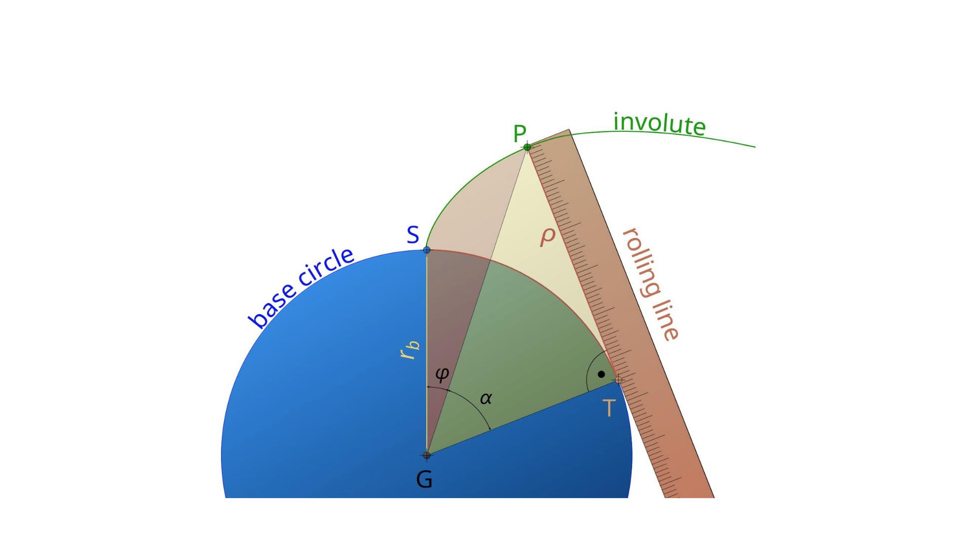
The image shows a labeled illustration used for involute gear calculation and geometry analysis. (tec-science)
Module and diametral pitch define tooth size. Metric gear systems use module, while inch-based systems use diametral pitch. Larger values create larger teeth with higher load capacity, while smaller teeth support compact assemblies.
Tooth size also affects machining. Fine-pitch gears need smaller cutters and tighter control during tooth generation. Larger gears usually allow easier cutting and inspection.
Tooth Count and Undercut Limitations
Very low tooth counts can create an undercut near the root area during gear cutting. Material removal at the tooth base weakens the tooth and changes contact behavior during operation.
For standard full-depth 20° involute gears, tooth counts below roughly 17 teeth become more susceptible to undercut unless profile modification is applied. Gear designers may adjust profile shift values to avoid unnecessary root loss.
Backlash and Center-Distance Control
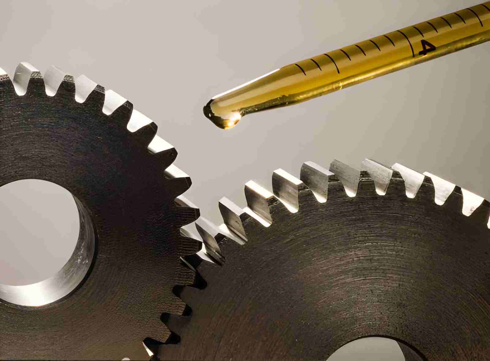
The image shows two involute gears being lubricated with a few drops of oil to reduce friction and wear. (iStock)
Backlash creates clearance between mating gear teeth during operation. Small clearance prevents tooth binding and allows lubrication space between surfaces.
Too little backlash can create noise and heat during operation. Excessive backlash increases movement between gears and affects positioning accuracy in drive systems.
Spur vs Helical Involute Gear Design
Spur gears use straight teeth cut parallel to the shaft axis. Manufacturing and inspection remain simpler because tooth geometry follows a direct path.
Helical gears use angled teeth that gradually enter contact during rotation. Tooth engagement becomes smoother, and load distribution improves, but machining complexity increases because tooth geometry follows a helical path across the gear face.
How to Draw an Involute Gear Profile
Gear drawings are usually created from calculated dimensions rather than manual tooth sketches. The profile depends on values such as module, pressure angle, pitch diameter, and tooth count because these dimensions control the final meshing behavior. In production drawings, the involute gear profile is usually generated parametrically instead of manually drafting each tooth flank.
Constructing the Involute Curve From the Base Circle
The tooth profile starts from the base circle. The involute curve develops outward from that reference instead of beginning from the gear outside diameter. The curve shape creates the working tooth surface that contacts the mating gear during rotation.
Traditional engineering methods used geometric construction steps to generate the curve. Modern CAD systems generate the profile automatically after gear parameters are entered.
Creating Gear Tooth Profiles in CAD Software
Most CAD software includes gear tools, scripts, or generators that create involute profiles from input values. Designers typically enter module, tooth count, pressure angle, and face width before the software builds the geometry.
The generated profile should still be checked before production. Imported models sometimes contain broken surfaces, profile gaps, or geometry that creates machining problems later.
Parametric Gear Modeling for CNC Manufacturing
Parametric modeling connects gear dimensions through linked values instead of fixed sketches. A change in tooth count or module updates related dimensions across the full model automatically.
This approach becomes useful during design revisions because gear ratios, shaft spacing, and tooth geometry often change before production begins.
Common Gear Drawing and Modeling Errors
Incorrect module values and pressure-angle mismatches create gear problems early in design. Gear pairs may appear correct visually, but still fail during assembly because the tooth geometry does not match.
Missing root clearance, incomplete profile definition, and wrong center-distance values also create machining and fit problems. These issues usually appear later during tooth cutting or gear inspection instead of during initial drawing review.
Involute Gear Profile Equations and Calculation
Gear drawings depend on a small group of dimensions that control tooth shape and gear engagement. These values are used during CAD modeling, inspection setup, and CNC manufacturing preparation.
Base Circle Formula
The involute profile starts from the base circle, which is derived from the pitch diameter and pressure angle.
db = d × cos(ϕ)
Where:
- db = base circle diameter
- d = pitch diameter
- ϕ = pressure angle
A higher pressure angle reduces the base circle size and changes the tooth flank shape. Base-circle size also affects the involute region available for cutting and inspection, especially on small-tooth-count gears.
Pitch Diameter Equation
Pitch diameter defines the working reference size of the gear used for spacing and meshing.
d = m × z
Where:
- d = pitch diameter
- m = module
- z = number of teeth
In inch systems, diametral pitch is used instead of module.
Pressure Angle Relationship
Pressure angle controls how force transfers between mating teeth during contact.
Standard industrial value: 20°
A 25° pressure angle usually leaves a thicker root section, which helps on heavily loaded gears. The tradeoff is higher radial loading on shafts and bearings, especially in compact gearbox layouts.
Center Distance Calculation
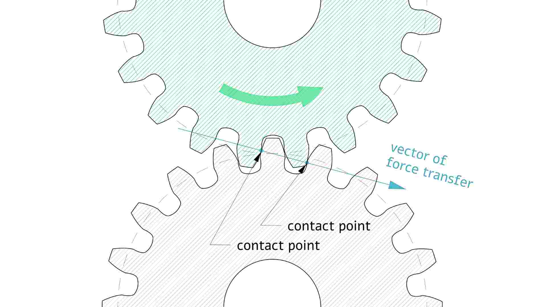
The image shows a labeled illustration of involute gears with the contact point and force transfer vectors marked on the drawing. (lcamtuf’s thing)
Center distance defines the shaft spacing between two meshing gears.
a = (d1 + d2) / 2
Where:
- a = center distance
- d1 = first gear pitch diameter
- d2 = second gear pitch diameter
Small changes in this value affect backlash and contact position after assembly.
Gear Ratio Formula
Gear ratio defines the speed and torque relationship between the driver and the driven gear.
i = z2 / z1
Where:
- i = gear ratio
- z1 = driver gear teeth
- z2 = driven gear teeth
Higher ratios increase torque and reduce output speed.
Advantages of Involute Gears
Involute gears are used in machine gearboxes, reducers, conveyors, automotive systems, and industrial equipment because they simplify both manufacturing and assembly. Many practical production advantages appear long before the gear reaches operation.
Constant Velocity Ratio During Meshing
As gear teeth rotate, contact moves gradually across the tooth flank instead of shifting suddenly. This keeps rotational movement more uniform and helps avoid speed fluctuation in drive systems.
Tolerance to Minor Center-Distance Variation
Perfect shaft spacing is difficult to maintain across machining, bearing fit, and assembly stages. Involute gears continue working reliably even with a small center-distance variation that naturally appears during production.
Easier Manufacturing and Tool Standardization
Most gear hobs, shaping tools, inspection systems, and CAD generators are built around involute geometry. Shops do not need completely different tooling for every gear profile, which simplifies production planning.
Stable Load Distribution and Smooth Operation
In long-running reducers, localized flank wear usually appears first near the pitch region if contact shifts too far toward one side of the tooth. Involute geometry helps keep the contact path more distributed during normal meshing. In practical use, this helps reduce localized wear on gearbox gears that run continuously under load.
Interchangeability and Manufacturing Scalability
Replacement gears become easier to produce if the module, pressure angle, and tooth count follow standard values. This becomes important in larger production programs because parts from different batches still need to fit and run correctly after assembly.
Manufacturing Methods for Involute Gears
Different gear jobs use different cutting methods. Production quantity, tooth accuracy, gear type, and material condition usually decide the process selection before machining begins.
Gear Hobbing for Production Manufacturing
Gear hobbing is widely used for external spur and helical gears because it maintains efficient cycle times across medium- and high-volume production.
This process is common for gearbox gears, transmission components, and industrial drive systems because the cycle time stays low once setup is complete.
Gear Shaping for Internal and External Gears
Some gear geometries create access limits during cutting. Internal gears, shoulder features, and close-wall designs often use gear shaping because the cutter can move into tighter areas.
Shaping takes longer than hobbing in many cases, but it allows production of geometries that standard hob cutters cannot easily reach.
CNC Milling for Prototype and Custom Gears
Prototype gears usually change several times before final production. CNC milling supports design updates because tooth geometry comes directly from CAD data instead of dedicated cutting tools.
This approach is common for development parts, small batches, and custom machine components where flexibility matters more than production speed.
Gear Grinding for High-Accuracy Applications
Heat treatment can slightly move gear teeth after cutting. Grinding removes a thin material layer from the tooth surface to correct profile variation and improve running quality.
Precision gearbox parts, servo systems, and high-speed assemblies often use gear grinding to correct profile deviation, improve gear quality grade, and reduce transmission noise at higher operating speeds.
Some prototype involute spur gears can be manufactured directly from metal plate using wire EDM cutting, especially for flat gear profiles where tooth geometry accuracy matters more than high-volume production efficiency. JLCCNC supports low-volume involute spur gear machining for prototype and custom mechanical assemblies.

Precision CNC Machining Service
Professional manufacturing, fast turnaround, and quality assurance.
Machining Challenges in Involute Gear Production
Gear errors are sometimes difficult to identify while cutting. Contact problems often become visible only after inspection or assembly testing.
Maintaining Tooth Profile Accuracy
Gear teeth repeat the same profile around the full part, so small variations become easier to notice across multiple teeth. A slight change in cutter position or setup alignment can shift tooth shape and affect contact across the gear.
Fine-pitch gears become more sensitive because there is less material and less profile space available for machining variation.
Tool Wear and Profile Deviation
As cutting edges wear, tooth geometry begins changing from one batch to the next. Tool-wear-related profile drift becomes more noticeable during longer production runs. Early parts may pass inspection while later parts start showing profile variation or tooth-spacing changes.
Burr Formation and Edge Quality
Small burrs commonly form near tooth exits after machining. Areas near the tooth tip and side edges often need secondary cleanup before assembly.
Even small remaining burrs can affect mating contact or create interference during inspection and fit checks.
Surface Finish and Tooth Contact Quality
Tooth surfaces do more than transfer motion. They continuously slide and roll against mating teeth during operation.
Rough tooth surfaces create more friction during contact. High-speed gearboxes and precision drive systems usually need tighter surface control because surface condition affects noise and wear behavior.
Gear Inspection and Measurement Methods
Outside diameter and tooth count alone are usually insufficient for evaluating full gear performance. A gear can meet drawing dimensions and still create noise or uneven contact during operation.
Production checks often include tooth profile inspection, runout measurement, pitch accuracy checks, and contact pattern testing because these values reflect actual gear behavior more accurately.
Materials and Heat Treatment for Involute Gears
Gear material decisions usually start from operating conditions instead of gear geometry alone. Running speed, impact loading, torque level, wear requirement, and production cost all affect material selection before machining begins.
Carbon Steel and Alloy Steel Gears
Medium-carbon steels such as 1045 are commonly used for general machine gears that run under moderate loads. Conveyor drives, machine reducers, and industrial equipment often use these materials because machining stays relatively straightforward.
For higher loading conditions, materials such as 4140, 4340, and 8620 are more common. These steels appear in transmission systems and industrial gearboxes where tooth loading stays high over long operating periods.
Aluminum and Lightweight Gear Applications
Aluminum gears usually appear in systems with lower torque demand. Test fixtures, robotics assemblies, prototype mechanisms, and CNC workholding tools often use aluminum because weight reduction becomes more important than maximum wear life.
Machining is faster compared with hardened steels, but softer tooth surfaces can wear sooner during repeated load cycles.
Heat Treatment and Surface Hardening
Gear teeth see repeated contact on the same working surfaces. Without hardening, tooth flanks gradually wear, and the tooth shape starts changing during operation.
Many shops rough-machine the gear first, perform heat treatment later, then finish-machine or grind critical areas if profile correction becomes necessary.
Material Selection Based on Load Conditions
Slow-moving inspection equipment does not need the same material as a heavily loaded gearbox. Higher torque and shock loading usually push material selection toward alloy steels with stronger wear resistance.
Lower-load assemblies often focus more on cost, machining time, or weight reduction during design selection.
Case Hardening vs Through Hardening
Case hardening keeps the outer tooth surface hard while leaving the core tougher underneath. Heavy-duty gears commonly use this approach because tooth surfaces handle wear while the inner section absorbs loading.
Through hardening increases hardness across the entire section thickness. Smaller gears with simpler loading conditions often use this method because processing stays more direct.
Applications of Involute Gears in CNC Manufacturing
Involute gears are used across machine systems because the tooth profile remains compatible with standard cutting, inspection, and assembly methods. The same geometry can scale from small positioning drives to large industrial reducers without changing the basic meshing principle.
High-Speed Transmission Systems
Electric motors, pumps, compressors, and industrial gearboxes commonly use involute gears because tooth contact stays predictable at higher rotational speeds. In these systems, small profile errors tend to appear quickly as vibration or running noise once RPM increases.
Surface finish and tooth accuracy usually matter more than cosmetic appearance. A gearbox running continuously at several thousand RPM reacts differently from a slow conveyor reducer with intermittent loading.
Precision Motion Assemblies
Servo drives, CNC rotary axes, and robotics joints often use involute gears where positioning repeatability matters during direction changes.
Backlash control becomes more sensitive in these assemblies. Even small tooth-spacing variation can affect indexing response or motion stability after repeated reversals.
Industrial Equipment and Custom Machine Builds
Reducers, conveyors, packaging equipment, and custom automation systems frequently use involute gears because replacement parts remain easier to source and reproduce.
For non-standard layouts, CNC machining allows gear geometry to be adjusted directly from CAD parameters. This is common during prototype work, where shaft spacing, reduction ratio, or housing dimensions continue changing before production is finalized.
Conclusion About Involute Gears
Involute gears stay in use because the same tooth form works with standard CNC gear cutting, hobbing, shaping, and grinding setups. The profile supports standardized tooling, which helps manufacturers produce different gear sizes without redesigning the entire cutting process.
In production, gear quality depends heavily on profile consistency during cutting, heat treatment, and finishing. Cutter wear, setup alignment, and machine rigidity affect tooth consistency more than the theoretical geometry on the drawing. Small profile shifts show up later as noise, uneven contact, or early wear.
Design choices like module, pressure angle, and tooth count directly affect machining time and tool selection. A small change in these values can move the job from standard hobbing to slower CNC milling or finishing operations.
At JLCCNC, involute gear drawings are checked before machining for tool access, cutting method, and production stability. Free DFM support helps adjust gear geometry for manufacturability, and parts can be produced from prototypes through full-volume runs.
JLCCNC reviews gear geometry for tool access, machining stability, and suitable production methods before cutting begins. From prototype gears to production batches, free DFM analysis helps identify manufacturability risks early.
Precision CNC Machining Service
Professional manufacturing, fast turnaround, and quality assurance.
FAQ About Involute Gears
Q: What is an involute gear profile?
An involute gear uses a tooth shape generated from a base circle curve. The profile keeps contact behavior stable during rotation and supports consistent motion transfer in gear systems.
Q: Why are involute gears preferred over cycloidal gears?
Involute gears maintain consistent motion transfer even with small center distance variation, making them easier to manufacture, assemble, and interchange in industrial applications. Cycloidal gears are more sensitive to alignment and manufacturing accuracy.
Q: What is the difference between involute and spur gears?
Involute describes the tooth profile geometry, while spur gear describes the gear type with straight teeth parallel to the shaft. Most modern spur gears use involute tooth profiles.
Q: Why are involute gears widely used in machinery?
They match standard manufacturing tools like hobs, shapers, and CNC gear cutters. Production becomes repeatable across different gear sizes without changing the basic cutting method.
Q: What are the advantages of involute gears?
They handle small shaft alignment variations without major meshing issues. Tooth contact stays smooth during rotation, which helps reduce noise and uneven wear in machine operation.
Q: How are involute gear profiles generated?
CAD systems generate the profile from inputs such as module, pressure angle, and tooth count. The software builds the curve mathematically instead of manual drafting.
Q: How do you draw an involute gear profile?
The process starts from the base circle and builds the tooth curve outward using calculated geometry. Modern CAD tools automate this using parametric gear functions based on standard gear equations.
Q: Can CNC machines produce involute gears accurately?
Yes, CNC machines can produce involute gears using milling, hobbing setups, and gear shaping systems. Accuracy depends on tool condition, machine rigidity, and setup control during cutting.
Keep Learning
Laser Engraving Aluminum: Marking Methods & Surface Effects
Key Takeaways Laser engraving usually removes base material to create a recess. Laser marking is a broader term that can describe a surface-color change or material removal, so the process name alone does not define the final result. On aluminum, alloy and surface finish affect marking contrast. A light mark on dark anodized aluminum is a common design target, but the actual appearance depends on the finish and laser process. JLCCNC laser marking produces a recessed area 0.03–0.1 mm deep. The result i......
CNC Cutting Fluid: Types, Functions, Applications, and Selection Guide
Key Takeaways Cutting fluid in machining performs four functions simultaneously: cooling the tool and workpiece, lubricating the tool-chip interface to reduce friction, carrying chips away from the cut zone, and protecting machined surfaces from corrosion between operations. Different machining operations need different fluid priorities: high-speed aluminum milling may need adhesion control and chip evacuation, threading and tapping need strong lubrication, and grinding requires both cooling and fine ......
Blind Hole Machining Guide: What Is a Blind Hole, Types of Holes, and Tapping Tips
What Is a Blind Hole? Types of Holes and CNC Hole Machining Explained In CNC machining, few operations challenge process control and tool stability as much as blind hole machining. A blind hole is a hole that terminates at a defined internal depth rather than breaking through the opposite surface. Because the cavity is enclosed at the bottom, chip evacuation, thermal behavior, tool wear, and dimensional accuracy become far more difficult to manage compared to through-hole machining. These constraints ......
Rake Angle in Machining: Machinists’ Guide to Perfect Cuts
What is Rake Angle? (minaprem) If you've ever stood in front of a CNC machine or a manual lathe, you know that the cutting tool's geometry isn't just some arbitrary design. Every angle, edge, and surface has a job to do, and one of the most important of those is the rake angle. We've been running machines long enough to know that rake angle can make or break your surface finish, tool life, and machining efficiency. In this guide, we're going to walk you through what rake angle is, how it works, and ho......
Sheet Metal vs CNC Machining: A Guide to Choosing the Right Method for Your Metal Parts
Quick Answer: Choose sheet metal for uniform-thickness enclosures, panels, and formed brackets when bends and production volume support lower unit cost. Choose CNC machining for variable wall thickness, precision bores, tight feature relationships, and complex 3D geometry. Use a hybrid design when a formed structure needs precision-machined interfaces. A quote comes back for a bracket, and it's priced as a CNC part — machined from solid aluminum, a few hours of spindle time, a per-part cost that makes......
What Steps Are Taken To Minimize Waste In CNC Machining Processes?
How to Reduce Waste in CNC Machining: 5 Practical Strategies Quick Answer: CNC machining waste is reduced mainly through DFM, near-net stock, efficient toolpaths, preventive tool maintenance, and alloy-segregated recycling. The biggest gains usually come before cutting: reduce unnecessary material removal and prevent scrap or rework. Every CNC-machined part starts as more material than it ends up being. A pocket gets milled out, a profile gets cut away, a boss gets faced down to size — and all of that......