Groove Machining in CNC Manufacturing: Types, Tools, and Precision Challenges
17 min
- What Is Groove Machining?
- Groove Machining vs Slotting and Other Machining Features
- Common Types of Groove Machining
- Groove Machining Tools and Process Stability
- What Usually Changes During Groove Machining
- Groove Cutting Changes Across Different Materials
- Common Problems in Groove Machining
- Designing Grooves for CNC Manufacturing
- How CNC Machine Capability Influences Groove Machining
- Conclusion About Groove Machining
- FAQ About Groove Machining
Key Takeaways About Groove Machining
- Groove CNC machining is widely used for O-ring seats, retaining ring features, bearing locations, and relief areas in mechanical parts.
- Groove width and depth are usually tied to functional requirements, not only machining dimensions.
- Internal and deep groove features often require dedicated grooving tools instead of standard cutting tools.
- In production, groove machining commonly uses multiple cutting passes to maintain width and bottom accuracy.
- Chip control becomes more important as groove depth increases because chips have limited space to escape the cutting zone.
- O-ring and sealing grooves usually receive tighter inspection because small dimensional changes can affect sealing performance.
- Tool overhang directly affects groove stability, especially during internal grooving operations.
- Groove machining on lathes and mills follows different cutting conditions based on feature orientation and access.
- Burr removal is commonly added after groove machining because sharp edges can affect assembly and part handling.
- Groove features often become final inspection points because they directly influence fit, movement, and sealing behavior in assembled parts.
Groove features are commonly added to machined parts for retaining rings, O-rings, seals, and component positioning. On the drawing, the feature often looks simple. This is because only width, depth, and location are shown. During machining, the process becomes more sensitive as the cutter works inside a confined area with limited space for chip removal.
As groove depth increases or feature width becomes smaller, machining conditions change. Chips can remain inside the cut, tool engagement becomes less stable, and wall accuracy becomes harder to maintain. These effects become more noticeable on internal grooves and sealing features where small dimensional changes can affect assembly.
In production, groove issues are often found after machining rather than during programming. Burrs, uneven bottoms, surface marks, and width variation usually appear after cutting starts, especially on deeper features or long-reach operations.
This article explains groove machining from a CNC manufacturing view, including groove types, tooling methods, chip control, and the practical challenges involved in machining groove features repeatedly.
What Is Groove Machining?
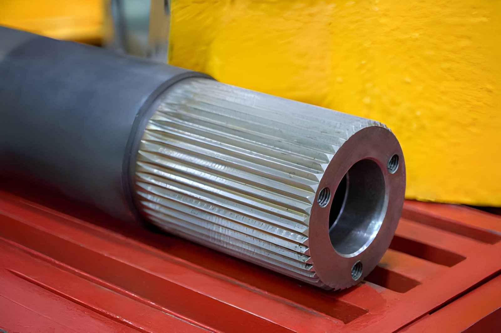
A close-up of a steel splined shaft for heavy machinery equipment - iStock
Groove machining is a CNC cutting process. It is used to remove material in a controlled width and depth to create narrow recessed features for sealing, retention, clearance, and assembly functions.
How Groove Machining Removes Material
- Groove machining removes material through prolonged tool engagement inside a defined path rather than across a wide open surface.
- The cutter enters a limited area first. It then gradually creates the required width and depth based on the feature design.
- Depending on part geometry, grooves can be machined on external diameters, internal bores, faces, and flat surfaces.
- Roughing and finishing passes are often separated to keep groove dimensions more consistent.
Difference Between Grooving and Standard Turning or Milling
Standard CNC turning and milling remove material from larger areas where the tool moves more freely across the workpiece. Groove machining cuts inside a narrow section, and the tool stays engaged within a fixed width.
Because of this, groove operations often use dedicated grooving tools and smaller step-by-step cuts. Internal grooves and deeper features also need more attention to tool reach and chip removal during machining.
Table 01: Difference Between Grooving and Standard Turning or Milling
| Aspect | Groove Machining | Standard Turning / Milling |
|---|---|---|
| Cutting area | Narrow section with fixed width | Larger open surface area |
| Tool contact | The tool stays engaged inside the groove | The tool moves freely across the surface |
| Tool type | Grooving inserts or slim cutters | General turning tools or end mills |
| Chip flow | Limited space for chip exit | More open space for chips |
| Tool reach | Often needs longer or internal reach tools | Usually short, stable tool access |
| Cutting method | Controlled cuts in small steps | Continuous material removal |
| Accuracy focus | Critical for sealing and fit features | General shaping and sizing |
| Typical use | O-rings, retention grooves, slots | Facing, profiling, pocketing |
Groove Machining vs Slotting and Other Machining Features
Grooves are often confused with slots, channels, and pockets because they all involve material removal in a defined area. In CNC work, the difference comes from function, depth-to-width ratio, and how the tool interacts with the cut.
Groove vs Slot
Grooves are usually functional features for sealing, retention, or positioning, while slots are typically through or open cuts used for clearance or assembly fit. Compared with slot milling operations, groove geometry is often controlled more tightly in depth, edge condition, and surface finish, especially in sealing areas.
Groove vs Channel
Channels are generally longer flow or passage features, often used in fluid or air movement applications. Grooves are shorter and more localized, usually tied to a specific mechanical function like holding an O-ring or snap ring.
Groove vs Pocket Machining
Pockets are larger recessed areas designed for material removal in more open cutting spaces. Unlike pocket milling strategies that prioritize material removal efficiency and toolpath flow, groove machining works inside much narrower paths where chip evacuation and tool stability become more restrictive.
Why Grooves Require Narrow Cutting Engagement
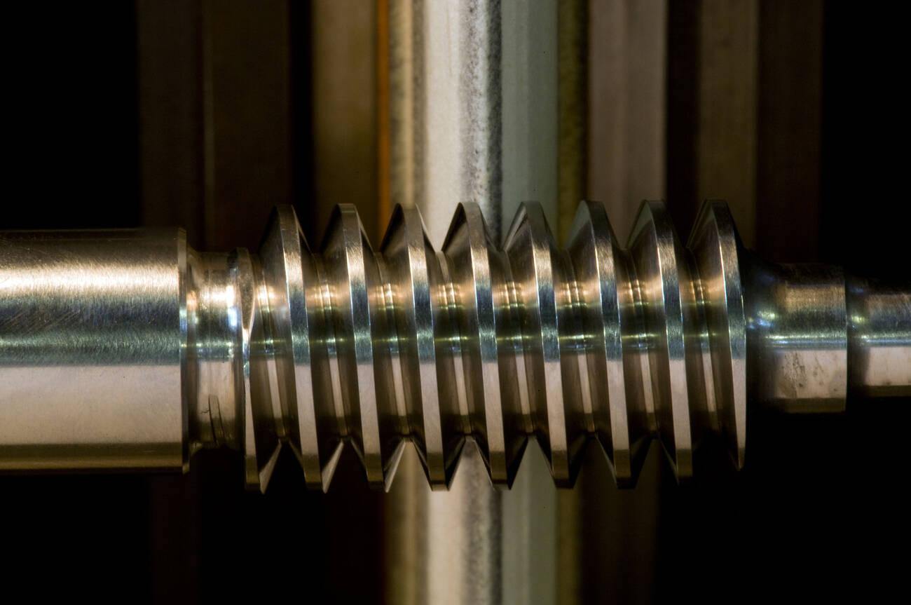
CNC grooving gear shaft - Alamy
Grooves are designed with a fixed narrow width, so the cutter must match that geometry closely. This means only a small section of the tool is active at any time, instead of a wide cutting contact.
As the cutting zone is tight, chips do not clear easily and tend to stay inside the groove until they are pushed out. This also reduces space for tool movement. Therefore, the cut depends heavily on tool stability and controlled feed.
In CNC shops, this is why grooving often uses dedicated inserts and careful depth steps instead of aggressive full-width cuts used in pockets and slots.
Common Types of Groove Machining
Groove type is mainly decided by where the feature sits and how the cutter can physically enter the cut. In CNC work, the geometry is less about naming and more about access, tool load direction, and how stable the cut stays during engagement.
External Grooving
External grooves sit on the outside diameter of shafts or turned parts. The tool engages from an open space, so the cutting load stays more stable, and tool monitoring is easier. These grooves are usually used where the feature must be visible and easy to inspect during assembly.
Internal Grooving
Internal grooves are cut inside a bore where tool entry is restricted by diameter. The cutter works in a confined space, so tool reach becomes the limiting factor. This setup makes chip exit harder and increases sensitivity to tool deflection during deeper cuts.
Face Grooving
Face grooves are machined from the front surface toward the center. The cutting condition changes continuously as the tool moves inward because the engagement angle keeps shifting. This makes consistency dependent on feed control and tool rigidity.
O-Ring and Seal Groove Machining
Seal grooves are not just geometry-based features; they are functional compression zones. The groove controls how much the elastomer deforms under pressure. If the width or depth shifts even slightly, sealing contact changes and leakage risk increase in real assembly conditions.
Thread Relief and Undercut Grooves
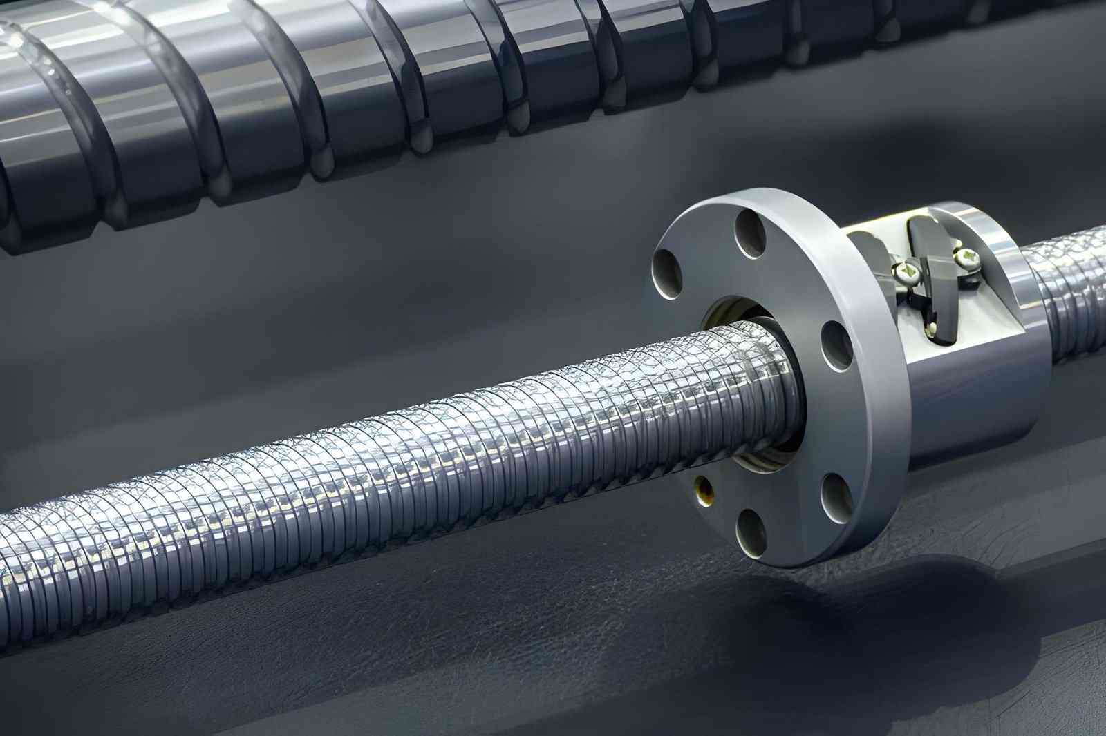
A close-up image of a lead ball screw set - iStock
Thread relief grooves are added at thread ends to give space for tool exit and prevent damage during termination. They also reduce stress concentration at the transition between threaded and non-threaded sections, which helps avoid cracking in high-load assemblies.
Groove Milling vs Groove Turning
Grooving Turning - Alamy
Groove turning works on rotating parts where the tool follows a fixed axis, which keeps cutting conditions more predictable. Groove milling is used when the feature is not aligned with a rotational axis, so tool engagement depends more on fixture stability and multi-axis control.
Groove Machining Tools and Process Stability
Groove machining depends on tool setup and cutting control inside a narrow space. The tool stays engaged in a small cutting zone, so stability issues show up quickly in depth, width, and surface condition.
Internal Grooving Tools and Insert Geometry
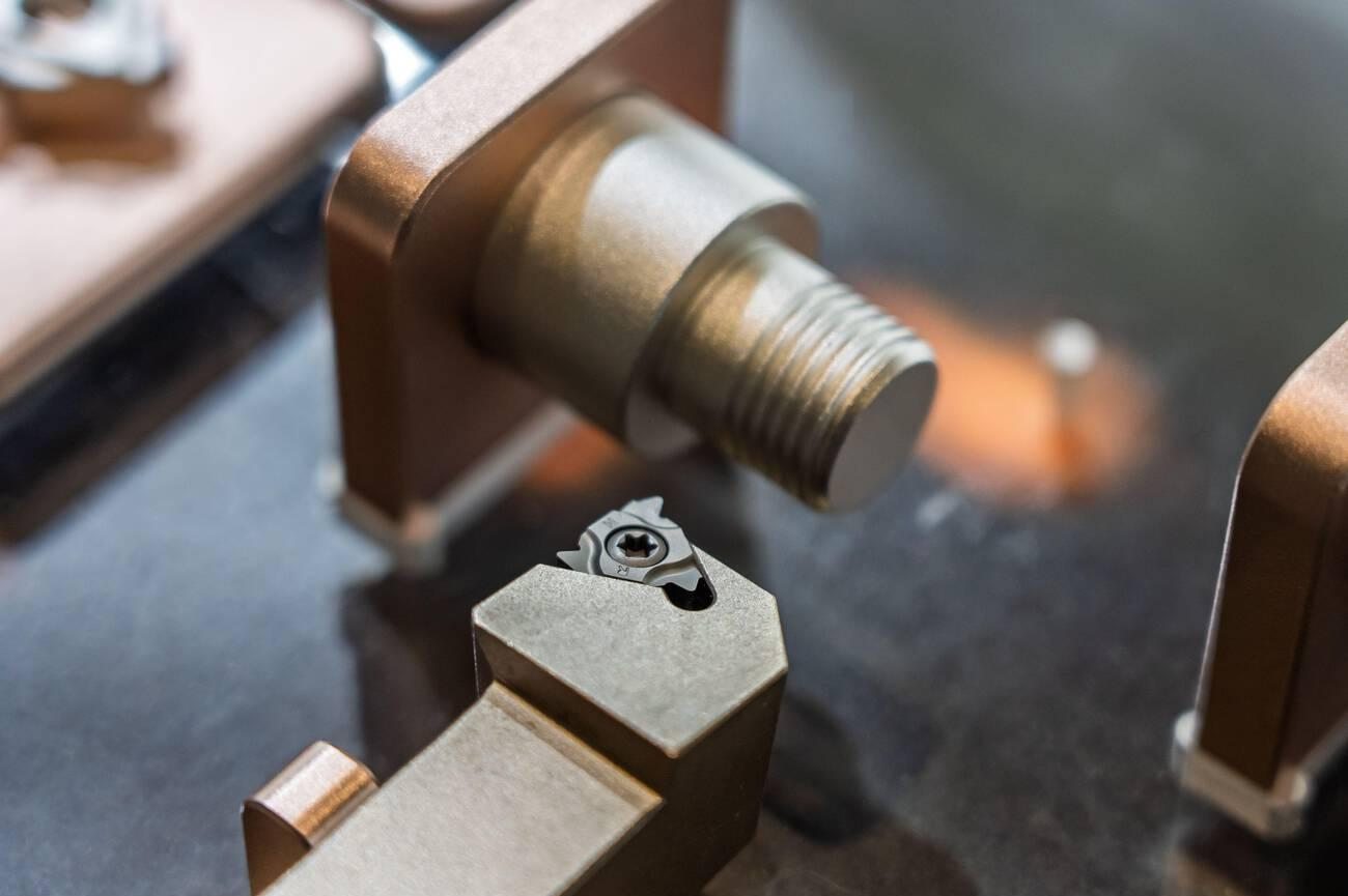
Grooving Tool - Alamy
Internal grooving tools are built for restricted access inside bores. Insert width sets the groove size, while nose geometry affects corner shape and bottom finish. In practice, tool choice usually starts from bore size, then moves to required groove depth and clearance.
Tool Overhang, Rigidity, and Machine Stability
As tool reach increases, rigidity drops, and cutting force starts influencing tool movement. This can appear as slight width variation or marks on groove walls during deeper cuts. Short tool length is preferred when geometry allows it, since it keeps cutting behavior more stable.
Coolant Delivery and Chip Evacuation
Grooves hold chips inside the cutting zone because there is limited exit space. If chips stay trapped, they affect the surface finish and increase the tool load in the next pass. Coolant direction is used to keep chips moving out of the groove during cutting.
CNC Turning vs Milling for Groove Features
CNC Turning is used when the groove follows a rotating axis, giving more consistent cutting conditions. Milling is used when the feature sits on a fixed or complex surface. In milling setups, stability depends more on fixture rigidity and tool path control.
Finishing Methods for Precision Grooves
Finishing passes are kept light to bring the groove size into the final range. Heavy cuts increase deflection inside narrow features and affect wall quality. After machining, edge cleanup is often done on sealing grooves to support proper assembly fit.
For sealing and high-precision applications, secondary finishing processes such as groove grinding or honing may be used after CNC machining to improve surface consistency and dimensional control.
What Usually Changes During Groove Machining
Groove Width Starts Changing Before the Tool Fails
Most groove problems appear gradually rather than suddenly. On deeper internal grooves, the first visible change is usually slight width variation caused by tool movement under load.
A groove may still measure close to nominal size at the opening while becoming inconsistent deeper in the cut. This is more noticeable on long-reach internal grooving tools where rigidity drops quickly as overhang increases.
For sealing grooves, even small width or depth variation can change how the seal compresses during assembly.
Chips Damage Groove Finish Faster Than Expected
Grooves trap chips naturally because the cutter works inside a narrow confined path. Once chips stop clearing consistently, the surface condition changes very quickly.
In aluminum, recut chips often leave smeared surfaces and burrs along groove edges. Stainless steel behaves differently. Heat concentration near the cutting edge becomes the larger issue during deeper cuts.
This is why coolant direction and chip evacuation matter more in groove machining than in many open cutting operations.
Groove Geometry Affects Assembly Performance Directly
Unlike cosmetic machined features, grooves usually control retention or sealing behavior inside an assembly.
An oversized retaining groove may reduce clip holding force. A shallow O-ring groove may over-compress the seal, while excessive depth can reduce sealing contact under pressure.
Because of this, groove features are often inspected more carefully than surrounding machined surfaces during production checks.
Groove Cutting Changes Across Different Materials
Aluminum grooves usually fail from chip packing before cutting force becomes the main issue. Long chips stay inside narrow grooves easily, especially during internal grooving, and surface finish can collapse quickly once chips begin recutting against the wall.
Stainless steel behaves differently. Work hardening and heat concentration increase cutting load progressively as the tool moves deeper into the groove. Long chip formation also makes chip evacuation less predictable during internal cuts.
Hardened steels create a different problem again. Cutting forces rise sharply, tool wear accelerates, and long-reach grooving tools become more sensitive to vibration and deflection during finishing passes.
Common Problems in Groove Machining
Groove machining issues usually come from tool access limits, chip control, and tool stability inside a confined cutting zone. These problems often appear during production rather than programming.
Oversized or Inconsistent Groove Width
Groove width can change when the tool deflects under cutting load. This is more common in long-reach or internal grooves where rigidity is lower. Even a small movement changes the fit of seals or retaining parts during assembly.
Poor Surface Finish Inside Grooves
Surface finish drops when chips stay inside the groove during cutting. Re-cutting of chips and unstable chip flow leave visible marks on groove walls and bottom surfaces. This is often seen in deep or narrow features.
Tool Breakage During Internal Grooving
Internal grooving tools are exposed to high stress because of limited clearance and overhang. Sudden chip load or poor chip evacuation can cause tool failure, especially during deeper passes or hard material cutting.
Burrs and Sharp Edge Formation
Burrs form at groove edges when the cutter exits the material under load. This is common in aluminum and ductile steels, where the material bends instead of breaking cleanly. Burrs often require secondary deburring before assembly.
Chip Packing in Deep Grooves
Deep grooves trap chips because there is limited space for evacuation. Packed chips increase heat and affect cutting stability in subsequent passes. This can also damage the tool edge over time.
Groove Distortion in Thin-Wall Parts
Thin-wall parts can deform during groove machining due to cutting pressure. When material support is weak, the wall shifts slightly under tool force, leading to uneven groove geometry after machining.
Designing Grooves for CNC Manufacturing
Groove design directly affects whether a feature can be machined consistently or will require extra setup and correction. In CNC work, manufacturability depends on how well geometry matches tool access, cutting stability, and inspection limits.
Groove Width and Depth Recommendations
Groove size is usually set by function, but machining limits still apply. In practice, groove widths below 1.0 mm increase tool break risk in steel, while wider grooves above 3 to 4 mm allow more stable cutting conditions.
Deep narrow grooves become progressively less stable as tool reach increases. Internal grooving operations are especially sensitive to overhang because rigidity drops quickly inside smaller bores. Beyond this range, tool deflection and chip packing become more noticeable, especially in internal features.
For O-ring grooves, ISO 3601 standards are commonly followed, where groove depth is controlled to achieve correct seal squeeze, usually around 10% to 30%, depending on the application.
Corner Radius and Tool Clearance Considerations
Internal groove corners cannot be perfectly sharp due to tool geometry. A minimum radius equal to the cutter nose radius is always present.
In production, a corner radius below 0.2 mm requires specialized inserts or EDM finishing. Larger radii improve tool life and reduce stress concentration in the groove base.
Tool clearance should also allow chip exit. Tight corner designs increase chip trapping and affect surface finish during cutting.
At JLCCNC, groove features are reviewed during DFM analysis to confirm tool access, chip evacuation, and dimensional feasibility before production begins.
Tolerance and Surface Finish Requirements
Groove tolerances depend on function. Sealing grooves often require ±0.02 to ±0.05 mm control in width and depth to maintain consistent compression.
Surface finish requirements vary. Static sealing grooves typically require Ra 1.6 to 3.2 µm, while dynamic sealing surfaces may require finer finishes around Ra 0.8 to 1.6 µm.
Tighter finishes increase machining time because feed rates must be reduced in the final pass.
Designing Internal Grooves for Machinability
Internal grooves are limited by tool reach and bore diameter. A practical design rule is to keep groove depth less than 2× bore diameter access when possible to maintain tool stability.
Chip evacuation must be considered early in design. Deep internal grooves without clearance slots often require multiple passes or coolant-assisted machining.
Reducing unnecessary depth and avoiding sharp transitions improves tool life and reduces the risk of chatter during internal grooving operations.
How CNC Machine Capability Influences Groove Machining
Groove results change with machine condition during cutting. The same program can give different groove quality on different machines because rigidity, access, and coolant flow affect how the tool behaves inside the cut.
Machine Rigidity and Spindle Stability
- In flexible machines, vibration shows first on the groove side walls as light waviness.
- Stable spindles keep groove width closer to tool size during repeated passes.
- Low rigidity setups often show more variation in deep or narrow grooves.
Tool Overhang and Reach Limitations
- Internal grooves often force long tool reach, which reduces cutting stability.
- Short tool setups give more consistent width control during side wall cutting.
- Deep grooves on long-reach tools usually need reduced feed to avoid deflection.
Coolant Delivery and Chip Control
- Grooves trap chips easily because there is no free exit path during cutting.
- Poor coolant direction leads to chip packing at the groove bottom.
- Packed chips can leave marks on the next pass and affect the final finish.
Multi-Axis Machining for Complex Groove Features
- Multi-axis access reduces the need for long tool reach in hard-to-access grooves.
- A better tool angle improves chip exit in non-standard groove positions.
- Fewer setups help keep groove position consistent from part to part.
Conclusion About Groove Machining
Groove machining is used in CNC parts where sealing, retention, or fit depends on a narrow cut feature. The groove is formed inside a limited cutting area, so tool behavior, chip flow, and access conditions directly affect final size and surface condition.
In machining, grooves do not behave like open cuts. The tool stays engaged inside a confined path, which increases load on the cutter and reduces chip exit space. This is where variation in width, depth, and edge condition usually starts.
Grooves are commonly used for O-rings, retaining rings, thread reliefs, and internal sealing areas. These features need a stable geometry because small changes affect sealing pressure and assembly fit during use.
Before production, groove design and tool access are checked to avoid cutting issues during machining.
Groove features are often tolerance-sensitive and difficult to correct after machining begins. Reviewing groove geometry early helps avoid tool access problems, chip packing, and sealing failures during production.
JLCCNC provides free DFM review for groove features, with CNC machining quotes starting from $1 and lead times as short as 3 days.

Precision CNC Machining Service
Professional manufacturing, fast turnaround, and quality assurance.
FAQ About Groove Machining
Q: What is groove machining?
Groove machining is a CNC cutting process used to create narrow cuts on shafts, bores, or flat faces. These grooves are used for seals, retaining rings, and assembly fit features.
Q: What is the difference between grooving and slot milling?
Grooving makes narrow, controlled features where the tool works inside a fixed width. Slot milling removes material in a wider open path for clearance or fitting. Grooving needs more control because there is less space for the tool and chips.
Q: What tools are used for internal grooving?
Internal grooving uses slim tools with carbide inserts designed to fit inside holes. The tool size depends on the bore diameter and groove depth. Deeper grooves need longer tools, but they are less stable during cutting.
Q: Why is chip evacuation difficult in groove machining?
Chips have limited space to escape because the groove is narrow and enclosed. In deep grooves, chips can stay trapped and affect surface finish or tool performance.
Q: What materials are easiest to groove with a machine?
Aluminum and mild steel are easier to machine because they cut smoothly and produce stable chips. Stainless steel and hardened materials are more difficult because they create heat and wear tools faster.
Q: When are grinding or honing used for groove finishing?
Grinding or honing is used when a very tight tolerance or a smooth surface is needed. It is common in sealing grooves or high-precision parts where CNC cutting alone is not enough.
Popular Articles
• Cutting with Precision: A Comprehensive Guide to CNC Water Jet Technology
• CNC Coolant Explained: Types, Maintenance & Safety
• Rake Angle in Machining: Machinists’ Guide to Perfect Cuts
• What Steps Are Taken To Minimize Waste In CNC Machining Processes?
• How EDM Wire Cutting Works: Complete Guide to Precision CNC Wire Cutting
Keep Learning
Chatter in Machining: Causes, Effects, and How to Reduce It
CNC milling operation producing visible chatter marks on an aluminum workpiece Quick Chatter Diagnosis Checklist Symptom Most Likely Cause First Action High-pitched squeal Regenerative chatter Change spindle speed ±15% Chatter only in deep pockets Excessive tool overhang Shorten tool Chatter on thin walls Low workpiece rigidity Improve fixturing Chatter after tool replacement Runout / holder issue Check tool holder Chatter only during finishing DOC too small / rubbing Increase feed or adjust speed It ......
What Is Tool Offset in CNC? Types, Setup & Best Practices
CNC tool offset setup with measurement overlay Key Takeaways CNC offsets connect programmed intent with actual cutter position. Length data guides Z-axis depth control. Radius data protects part size during contour milling. Geometry values define the cutter's measured baseline. Wear values support fine correction during production. Verified data lowers scrap risk before full machining. Good offset habits protect tools, fixtures, and parts. In the context of CNC machining , tool offset is the quiet set......
Trochoidal Milling: Complete Guide to High-Efficiency CNC Machining
Key Takeaways Trochoidal milling combines circular cutter motion with continuous forward feed. The cutter normally engages 5 to 20% of its diameter instead of making a full-width cut. A smaller engagement angle limits force changes during slotting and pocket roughing. Low radial engagement often allows greater axial depths of cut than conventional slot milling. CAM software calculates the circular path automatically from the selected machining parameters. This strategy is widely applied to titanium, s......
What Is Die Casting? Process, Materials, and Applications
Key Takeaways Die casting is a metal casting process that forces molten metal into a reusable steel mold under high pressure, producing parts with tight tolerances and good surface finish at high volume. Aluminum die casting is the most common form by far, thanks to its combination of light weight, decent strength, and good corrosion resistance. The die casting process runs through mold preparation, injection, cooling, and ejection in a cycle that can repeat every few seconds to minutes depending on p......
First Angle vs Third Angle: Understanding Orthographic Projection Methods
Key Takeaways Orthographic projection is the system that lets a 3D part be represented through multiple 2D views, front, top, side, and so on. First angle projection and third angle projection are the two standard methods for arranging those views, and they place views in opposite positions relative to the object. First angle projection is the ISO standard used across most of Europe, India, China, Russia, and many other countries following ISO standards Third angle projection is the standard in the Un......
Micro EDM Machining: Capabilities, Materials, and Applications for Precision Components
Key Takeaways About Micro EDM Machining Only electrically conductive materials can be machined. Hole diameters can reach below 50 μm on specialized equipment. The process produces almost no mechanical cutting force, making it suitable for thin or delicate features. Surface integrity still requires attention because recast layers and heat-affected zones may remain after machining. Micro EDM is often combined with CNC machining, with milling producing the main geometry before EDM finishes critical micro......