What Is a CNC Post Processor? How CAM Toolpaths Become Machine-Ready G-Code
10 min
- What Is a CNC Post Processor
- How a CAM Post Processor Translates Toolpaths into Machine Code
- Why There Is No Universal CNC Post Processor Across Machines
- Types of CNC Post Processors (Generic vs Custom)
- How to Choose the Right CNC Post Processor
- How to Modify or Customize a Post Processor
- Errors and Their Impact: What Happens When Post Processing Goes Wrong
- Post Processor vs G-Code: Why Output Alone Is Not Enough
- Best Practices in Real CNC Projects
- FAQs About CNC Post Processors
In CNC machining, generating a toolpath in CAM does not mean the program is ready for the machine. The gap between digital toolpath planning and actual machine execution is handled by a post processor.
Different machines, controllers, and kinematic setups interpret motion instructions differently, which is why the same CAM file cannot be used directly across systems without translation.
Key Takeaways About Post Processor
- A post processor does not generate CNC toolpaths. It defines how CAM output is structured into controller-level instructions.
- The same CAM program can produce different machine behavior depending on controller format, kinematics, and post configuration.
- Output issues such as alarms, motion errors, or poor surface finish are often linked to post processing rather than toolpath strategy.
- There is no universal CNC post processor. Each machine and control combination requires tailored output logic.
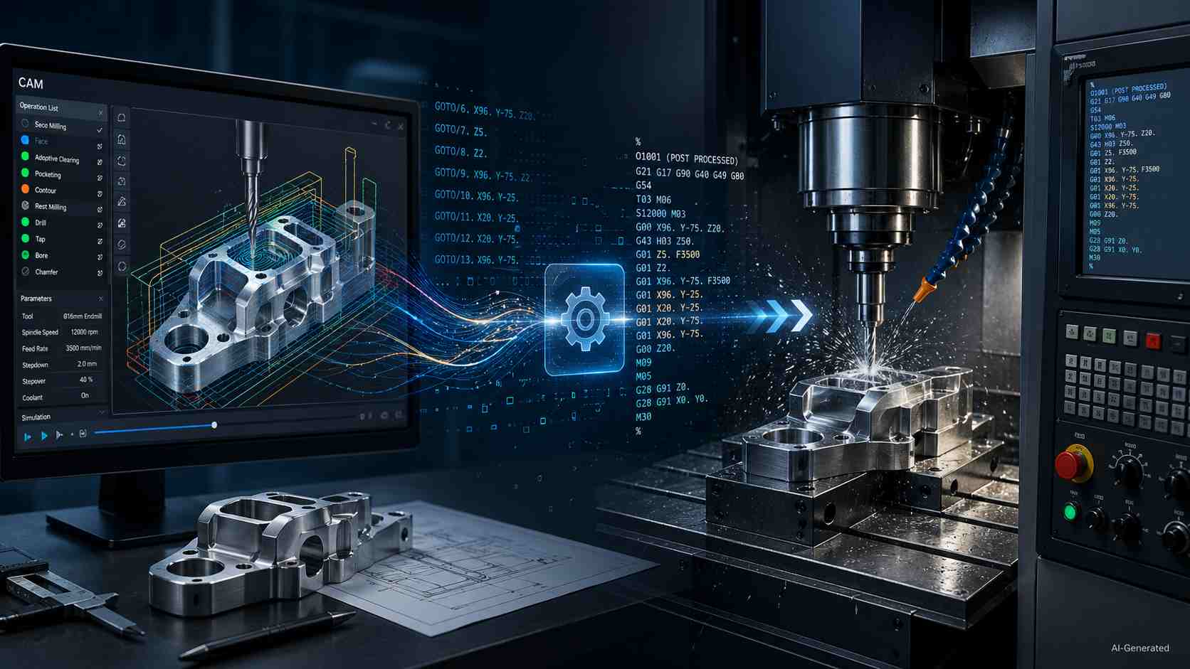
CAM toolpath to CNC G-code workflow
What Is a CNC Post Processor
A CNC post processor is a software component that converts CAM toolpaths into machine-specific G-code instructions, ensuring compatibility with a given CNC controller, machine kinematics, and machining setup.
After CAD defines the part and CAM plans the cutting path, the post processor generates the final NC program before it reaches the control. In practice, the CAM post processor defines how toolpath intent is translated into machine-readable instructions.
How a CAM Post Processor Translates Toolpaths into Machine Code
CAM Toolpath Output vs Machine-Readable Code
Typically, CAM holds cutter movement as planned positions, feeds, and operation data. A CNC machine requires a structured NC file with defined startup blocks, coordinate modes, units, compensation states, and program termination logic.
Translation into Controller-Specific G-Code
During post processing, the post processor applies rules for the target control. It defines command words, sequence structure, canned-cycle format, rotary-axis behavior, and output formatting based on the controller’s expected syntax and machine configuration.
Example (simplified):
CAM output intent:
Move tool to position X50 Y25 at feed 500
Post-processed G-code (Fanuc-style):
G90 G17 G01 X50 Y25 F500
This output includes modal states such as absolute positioning (G90) and plane selection (G17), which are typically handled automatically by the post processor rather than defined explicitly in CAM.
On a different control, the same motion may be formatted differently depending on modal defaults, feed interpretation, or machine configuration.
Why the Same CAM File Produces Different Results on Different Machines
A CNC post processor may write different motion lines from the same CAM data. The reason is that each machine has its own axis limits, kinematic layout, controller settings, supported cycles, and safety habits, which influence motion behavior at the control level.
Why There Is No Universal CNC Post Processor Across Machines
Controller Differences and Supported G-Code Variants
A single shop may operate multiple CNC controls that accept standard G and M codes. Nevertheless, each control may still expect its own word order, modal defaults, subprogram format, and alarm rules. A CNC machine post processor accounts for those habits, which is why code written for one control can behave unpredictably on another.
Machine Kinematics and Axis Definitions
Machine layout introduces another layer of complexity: a three-axis mill, a five-axis head-table machine, a router, a lathe, or a mill-turn unit may all describe motion in different axis relationships. It is the responsibility of a CAM post processor to incorporate that geometry into the NC output, which affects rotary directions, pivot behavior, retract moves, and travel choices.
Built-In Cycles, Limits, and Syntax Constraints
In addition, built-in cycles and command limits set the rules for what the control will accept without complaint, such as drilling routines, compensation calls, arc formats, and line structure. This is why a universal post processor cannot reliably support all machines. Not just the cutter path, but also the machine's available functions must be included in the final program.
Types of CNC Post Processors (Generic vs Custom)
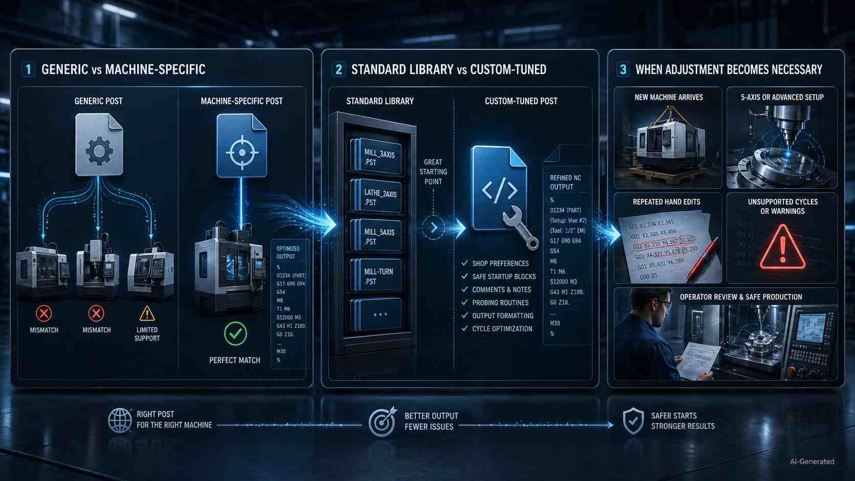
Types of CNC post processors infographic
Generic vs Machine-Specific Post Processors
Generic posts are often used for initial validation, while production work typically relies on machine-specific output. Yet, a machine-specific file is chosen when the control, tooling habits, and shop preferences need closer alignment. In production, that choice affects fewer manual edits and a smoother path from CAM to NC output.
Standard Library vs Custom-Tuned Post Processors
Library files give programmers a starting point for familiar machine-control combinations. However, a tuned post processor becomes valuable when the shop wants preferred comments, safer opening blocks, probing calls, or special handling in the program from the start.
When Post Processor Adjustment Becomes Necessary
Adjustment is important when a new machine arrives, an added axis changes movement logic, a controller option changes cycle support, or operators keep fixing the same output by hand. At that point, refining the CNC post processor assures consistency across repeat work.
How to Choose the Right CNC Post Processor
Matching the CNC Controller
A CNC machine post processor must match not only the controller type, but also the specific machine configuration and enabled functions.
It is important to begin with the control because each one has its own command style, file habits, and acceptable program patterns. Keep in mind that the appropriate CNC post processor will accommodate those expectations before the task is sent to the machine.
Considering Machine Axis Configuration
Examine the machine configuration next. A 3-axis mill has a different set of output options than a 5-axis setup, which is characterized by rotational direction, tool angle, travel range, and machine geometry, all of which have an impact on the way the program is executed.
When You Need a Custom Post Processor
When a shop employs particular probing, preferred safety lines, unique file formats, or repetitive manual changes, it is a hint that the output should match the workflow more closely. This is the case when a custom post processor becomes worthwhile for the shop.
How to Modify or Customize a Post Processor
Common Customization Scenarios
Shops adjust a CNC machine post processor whenever daily programs need shop notes, probing routines, preferred tool-call wording, or cleaner operator messages. Post processor customization typically starts when repetitive manual edits appear in daily production. The team continues to make the same adjustments by hand, and then they transfer that rule upstream into the posted file.
Editing Output Format and Machine Cycles
From there, a CAM post processor can be tuned for decimal places, line numbering, block endings, tool-change sequence, coolant timing, drilling cycle style, arc output, and optional stops. This reduces the need for manual edits by aligning the NC output with the control’s expected behavior.
Risks of Incorrect Modifications
Incorrect modifications can introduce serious risk since a misplaced sign, missing modal command, wrong offset call, or unsafe retract might force the cutter to go in a direction that was not intended. Before any edited file reaches production, it should be validated against the machine manual, verified in simulation, and proven through cautious dry runs.
Errors and Their Impact: What Happens When Post Processing Goes Wrong
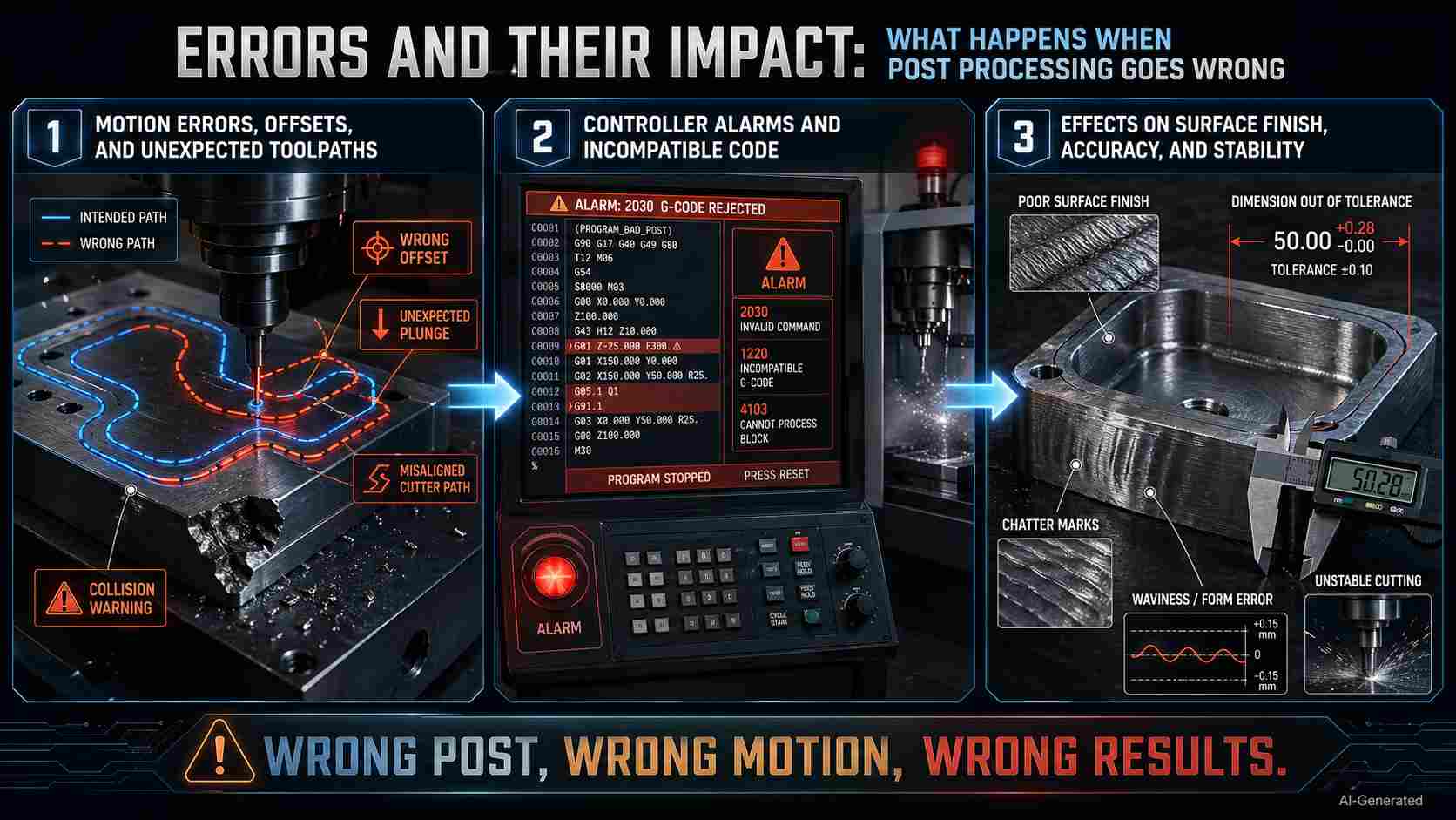
CNC post processing errors and impacts
Motion Errors, Offsets, and Unexpected Toolpaths
When the NC file carries the wrong offset call, plane selection, arc direction, or retract height, the cutter can drift away from the intended path as well as approach fixtures or stock from a risky angle. At that point, the problem becomes physical rather than computational, often resulting in scrap, broken tooling, or halted production.
Controller Alarms and Incompatible Code
The next warning appears at the control panel when unsupported code, missing tool numbers, invalid feed commands, or syntax errors stop the program. That pause delays the job while the programmer and operator trace the bad line back to its source.
Effects on Surface Finish, Accuracy, and Stability
Even when the program runs, a mismatched CNC post processor can leave behind rough finishes, size drift, chatter, uneven motion, or unstable cutting. This occurs because feed behavior, acceleration, arcs, and compensation may not be suitable for the machine. The part may come off the table looking close and then fail inspection where it counts.
Post Processor vs G-Code: Why Output Alone Is Not Enough
The Role of the Post Processor in Generating G-Code
G-code is the primary machine-readable instruction format used in CNC systems, while the post processor defines how CAM intent is translated into controller-specific instructions. Practically, the CNC post processor gives G-code its machine context, which is why output quality starts before the operator loads the file.
Why G-Code Is Not Universally Transferable Between Machines
A copied NC file may look familiar on screen, but another control may read modal states, arcs, cycles, offsets, or machine commands differently. That gap is the reason one program can run well on its intended machine and create alarms, odd movement, or inspection trouble on another.
Best Practices in Real CNC Projects
Matching CAM Output to Machine Capability Before Production
Before a job reaches the floor, check that the NC file agrees with travel range, spindle options, tool changer behavior, coolant setup, fixture space, and control features. A CNC machine post processor should support the equipment you actually plan to use, not an ideal version of it.
Verifying and Simulating Programs to Avoid Runtime Issues
Next, prove the program away from cutting pressure by reviewing the posted NC file, using simulation, and making a cautious dry run when needed. This helps catch collisions, gouges, bad motion, and tool-reach problems before material, cutters, or machine time are at risk.
Working with Unknown or Third-Party Post Processors
When a CAM post processor comes from an outside source, treat it like an unproven setup. Compare its output against the controller manual, test a low-risk part first, keep the original file backed up, and document any approved edits before production work depends on it.
In real CNC production, correct post processing is only one part of the workflow. Reliable machining also depends on machine capability, setup stability, and process control.
At JLCCNC, we bridge the gap between digital toolpaths and real machining results by combining CNC machining expertise with production-ready execution.
Upload your CAD file to get an instant quote starting from $1, with lead time as fast as 3 days.

Precision CNC Machining Service
Professional manufacturing, fast turnaround, and quality assurance.
FAQs About CNC Post Processors
Q: Can the same G-code run on different CNC machines without a post processor?
Sometimes, but only when machines share similar controls, configurations, and command rules. Otherwise, a file that works well on one machine could halt, alarm, or move in a different manner on another machine.
Q: Do all CAM systems include a CNC post processor?
Different CAM systems come with a starter library of post processors. Nonetheless, before the shop can utilize the available options, it is necessary to review them. This is because each file must correspond to the machine, control, and enabled features behind the job.
Q: When should a CNC post processor be modified or customized?
Modification becomes a necessity when posted code needs repeated manual edits, when the shop adds new machine functions, when operator comments must follow an internal style, or when the control requires a different cycle format than the current file produces.
Q: What are the risks of using the wrong post processor?
The wrong file can create bad tool calls, unsupported commands, offset mistakes, rough motion, scrap parts, or downtime, which is the reason why machinists consider post selection to be an integral aspect of process control rather than a casual export decision.
Popular Articles
• Cutting with Precision: A Comprehensive Guide to CNC Water Jet Technology
• CNC Coolant Explained: Types, Maintenance & Safety
• Rake Angle in Machining: Machinists’ Guide to Perfect Cuts
• What Steps Are Taken To Minimize Waste In CNC Machining Processes?
• How EDM Wire Cutting Works: Complete Guide to Precision CNC Wire Cutting
Keep Learning
Chatter in Machining: Causes, Effects, and How to Reduce It
CNC milling operation producing visible chatter marks on an aluminum workpiece Quick Chatter Diagnosis Checklist Symptom Most Likely Cause First Action High-pitched squeal Regenerative chatter Change spindle speed ±15% Chatter only in deep pockets Excessive tool overhang Shorten tool Chatter on thin walls Low workpiece rigidity Improve fixturing Chatter after tool replacement Runout / holder issue Check tool holder Chatter only during finishing DOC too small / rubbing Increase feed or adjust speed It ......
What Is Tool Offset in CNC? Types, Setup & Best Practices
CNC tool offset setup with measurement overlay Key Takeaways CNC offsets connect programmed intent with actual cutter position. Length data guides Z-axis depth control. Radius data protects part size during contour milling. Geometry values define the cutter's measured baseline. Wear values support fine correction during production. Verified data lowers scrap risk before full machining. Good offset habits protect tools, fixtures, and parts. In the context of CNC machining , tool offset is the quiet set......
Trochoidal Milling: Complete Guide to High-Efficiency CNC Machining
Key Takeaways Trochoidal milling combines circular cutter motion with continuous forward feed. The cutter normally engages 5 to 20% of its diameter instead of making a full-width cut. A smaller engagement angle limits force changes during slotting and pocket roughing. Low radial engagement often allows greater axial depths of cut than conventional slot milling. CAM software calculates the circular path automatically from the selected machining parameters. This strategy is widely applied to titanium, s......
What Is Die Casting? Process, Materials, and Applications
Key Takeaways Die casting is a metal casting process that forces molten metal into a reusable steel mold under high pressure, producing parts with tight tolerances and good surface finish at high volume. Aluminum die casting is the most common form by far, thanks to its combination of light weight, decent strength, and good corrosion resistance. The die casting process runs through mold preparation, injection, cooling, and ejection in a cycle that can repeat every few seconds to minutes depending on p......
First Angle vs Third Angle: Understanding Orthographic Projection Methods
Key Takeaways Orthographic projection is the system that lets a 3D part be represented through multiple 2D views, front, top, side, and so on. First angle projection and third angle projection are the two standard methods for arranging those views, and they place views in opposite positions relative to the object. First angle projection is the ISO standard used across most of Europe, India, China, Russia, and many other countries following ISO standards Third angle projection is the standard in the Un......
Micro EDM Machining: Capabilities, Materials, and Applications for Precision Components
Key Takeaways About Micro EDM Machining Only electrically conductive materials can be machined. Hole diameters can reach below 50 μm on specialized equipment. The process produces almost no mechanical cutting force, making it suitable for thin or delicate features. Surface integrity still requires attention because recast layers and heat-affected zones may remain after machining. Micro EDM is often combined with CNC machining, with milling producing the main geometry before EDM finishes critical micro......