Peripheral Milling vs Face Milling: Key CNC Differences
21 min
- What Is Peripheral Milling?
- What Is Face Milling?
- Common Peripheral Milling Operations
- How Peripheral Milling Differs From Face Milling
- How Peripheral Milling Differs From Face Milling
- Cutting Tools and Machine Setup for Peripheral Milling
- Common Machining Problems in Peripheral Milling
- When to Use Peripheral Milling vs Face Milling
- Conclusion About Peripheral Milling
- FAQ About Peripheral Milling
Quick Comparison: Peripheral Milling vs Face Milling
| Factor | Peripheral Milling | Face Milling |
|---|---|---|
| Where cutting happens | Outer circumference of the cutter | Face (bottom) of the cutter |
| Cutting force direction | Horizontal, into or against feed direction | Primarily downward, into the workpiece |
| Surface generated | Vertical walls, slots, profiles, contours | Flat horizontal surfaces |
| Typical tools | End mills, side and face cutters, slitting saws | Face mills, shell mills, fly cutters |
| Spindle orientation | Usually vertical, can be horizontal | Usually vertical |
| Surface finish quality | Good on walls, stepover marks on floors | Excellent on flat faces |
| Best application | Pockets, slots, profiles, contours | Large flat faces, facing operations |
| Chip thickness pattern | Starts thin, thickens (conventional) or thick to thin (climb) | More uniform during cutter engagement |
| Radial force on spindle | High | Low |
| Axial force on spindle | Low | High |
| Width of cut flexibility | Full diameter down to 5% engagement | Typically limited by cutter diameter and surface coverage requirements |
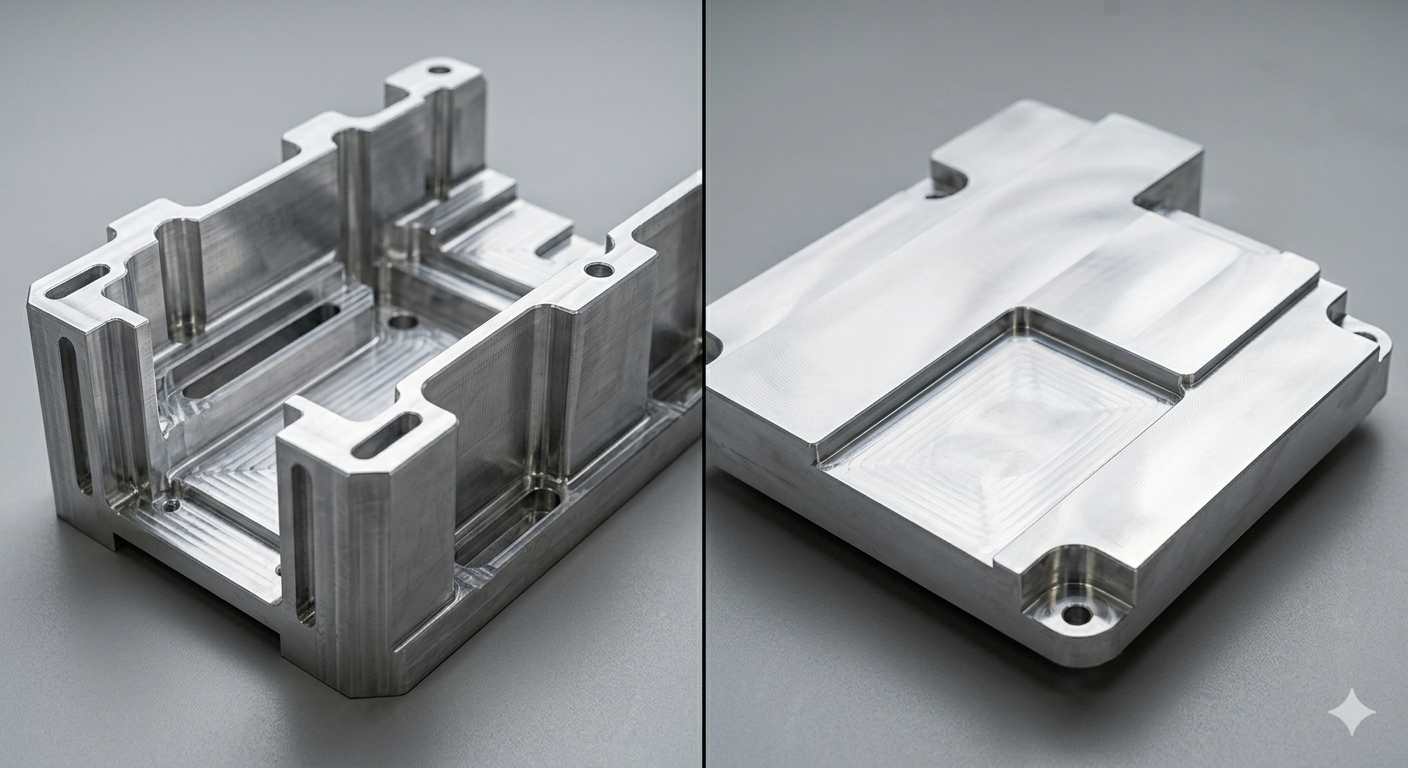
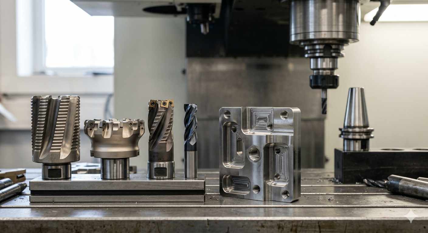
(AI generated) finished CNC machined parts comparing face milling vs peripheral milling
Here's something that catches people out early in their machining education. Two operations, similar-looking tools, same CNC machine, but completely different cutting behavior, different surface finish, different force direction, and different applications. Peripheral milling and face milling aren't interchangeable names for the same thing. Understanding what separates them changes how you think about tool selection, setup rigidity, and why some operations leave better surfaces than others.
What Is Peripheral Milling?
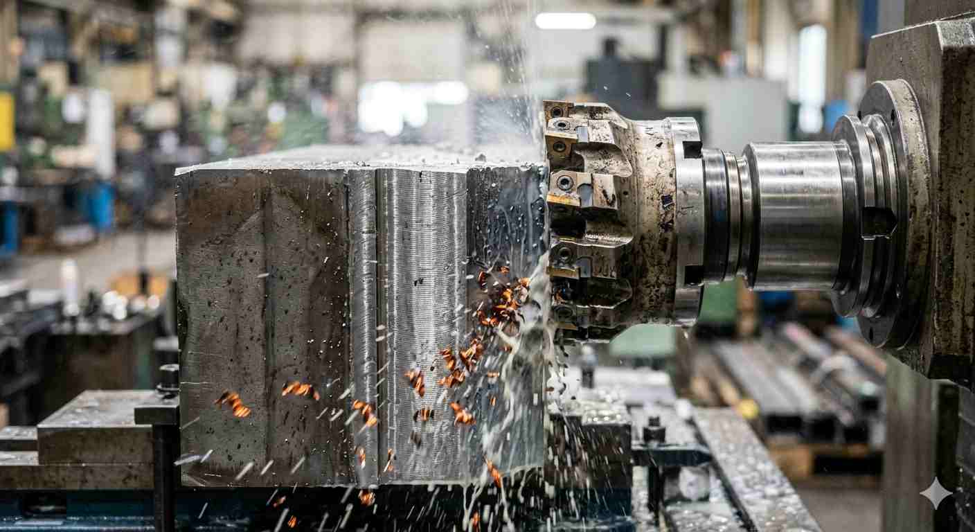
(AI generated) peripheral milling operation cutting the side wall of a steel
What is peripheral milling? It is a milling operation where material is removed by the cutting edges on the outer circumference of the cutter, with the machined surface generated parallel to the cutter axis.
How Peripheral Milling Removes Material
Picture an end mill cutting a slot. The teeth doing the work aren't on the bottom of the tool, they're on the sides, around the cylindrical body. As the cutter rotates and feeds into the material, those side teeth peel chips off the workpiece. The surface left behind runs parallel to the tool's rotational axis, which is why peripheral milling operation produces vertical walls, side profiles, and contoured features rather than flat horizontal faces.
The chip formation in peripheral milling follows a specific pattern depending on whether you're climb milling or conventional milling. In conventional milling, each tooth enters the cut at zero chip thickness and exits at maximum thickness, the tooth starts rubbing before it bites, which generates heat and accelerates wear but is more forgiving on machines with backlash. In climb milling, each tooth enters at maximum chip thickness and exits at zero, cleaner cutting, better surface finish, less heat, but it loads the tooth harder at entry and requires a rigid setup with no table backlash.
The radial forces in peripheral milling are significant. The cutter is pushing against the workpiece horizontally, that force tries to deflect the tool away from the cut and push the workpiece sideways in its fixture. Long end mills deflecting under radial load are one of the most common causes of tapered walls and poor surface finish in peripheral milling operations. Shorter tool stickout, higher rigidity fixturing, and reduced radial depth of cut all address this. Peripheral milling typically introduces higher radial force components under comparable axial engagement conditions, especially in long-reach tool setups.
The width of cut in peripheral milling, called radial depth of cut or stepover, directly controls how much of the cutter diameter is engaged. Running 50% stepover on a 20mm end mill puts 10mm of the diameter in contact with the material. Running 10% stepover puts 2mm in contact. Lower engagement means lower cutting forces, less heat, and the ability to run significantly higher feed rates, which is the principle behind high-speed machining strategies that use shallow radial engagement at aggressive feeds to remove material faster than conventional full-width passes while generating less tool load.
What Is Face Milling?
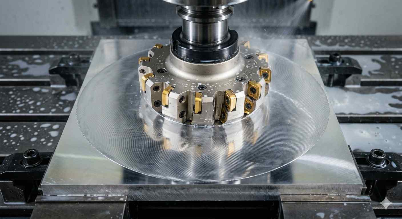
(AI generated) face milling cutter machining a flat aluminum surfac
Face milling is a CNC milling operation where the cutter removes material primarily with the cutting edges on the face of the tool, generating a flat surface perpendicular to the spindle axis.
A lot of people confuse face milling with “just flattening a surface,” but the mechanics are different from most side-cutting operations. The cutter orientation changes everything. In face milling, the spindle comes down vertically onto the workpiece, and the majority of cutting happens across the bottom face of the cutter rather than along the sidewalls.
Face milling often determines the visual quality and flatness consistency of machined surfaces, especially on exposed aluminum and tooling components.
And, face milling is often doing more than making something flat. It's usually establishing the reference surface that every later machining operation depends on. If that first face isn't stable, square, and dimensionally consistent, the rest of the part starts stacking error on top of error. That's where things get expensive fast.
How Face Milling Removes Material
Most face mills still generate some cutting action along the insert periphery during engagement. The cutter rotates perpendicular to the surface while feeding laterally across the material, shearing away a thin layer with every insert engagement.
Unlike peripheral milling operation, where the cutter side generates the surface geometry, face milling creates the finished surface from the cutter's face path itself. That changes force direction significantly.
Most cutting force in face milling pushes downward into the machine table instead of sideways into the workpiece. That's one reason large CNC machining centers love face milling for heavy stock removal. The setup stays more stable because the machine structure naturally resists vertical loading better than lateral deflection.
There's also a chip-thinning effect that shows up with large-diameter face mills. A 63 mm or 80 mm cutter running shallow axial depth but high feed per tooth can remove material surprisingly fast without overloading inserts. That's why modern high-feed face mills can push feed rates above 2,000-4,000 mm/min in aluminum and still leave respectable finishes.
The insert geometry matters too. A face mill using positive-rake inserts cuts smoother and requires less spindle power, especially in stainless or softer aluminum alloys. Negative-rake cutters survive abuse better in cast iron and roughing passes but increase cutting pressure substantially. You feel that difference immediately on lighter machines.
And then there's insert count. More inserts sound better on paper, but not always in reality. A face mill with ten inserts demands more spindle horsepower than a five-insert cutter at the same feed per tooth. Smaller VMCs sometimes perform better with fewer inserts because the machine can maintain spindle speed under load instead of bogging down halfway through the cut.
That surprises newer programmers sometimes.
Typical Face Milling Applications
Face milling shows up almost everywhere in CNC machining because flat surfaces are everywhere. Machine bases, fixture plates, hydraulic manifolds, mold plates, aerospace brackets, gearbox housings, medical mounting surfaces, even simple aluminum spacers all rely on face milling at some stage.
The operation is especially common during the first setup of billet machining. Raw stock rarely arrives perfectly flat. Hot rolled steel carries scale and warpage. Saw-cut aluminum plate may vary several tenths across the surface. Face milling establishes a clean datum before precision machining starts.
For large steel components, carbide inserted face mills often remove 2-6 mm of stock per pass during rough surfacing. Aluminum machining can go even more aggressive depending on spindle power and cutter diameter. Some high-speed aerospace setups run 100 mm face mills at spindle speeds over 10,000 RPM with material removal rates that sound almost ridiculous if you've only worked on manual mills.
Surface finish expectations vary too. A roughing face mill may leave Ra values around 3.2-6.3 µm. Finishing cutters with wiper inserts can push below Ra 0.8 µm under stable conditions. That's smooth enough that the surface almost looks ground from certain angles.
One small thing machinists learn pretty quickly: cutter diameter affects finish consistency more than people expect. If the cutter barely overlaps the workpiece width, the surface pattern becomes asymmetrical and exit marks get ugly. Ideally, the face mill diameter should exceed workpiece width by roughly 20-30% whenever possible.
Not always practical, obviously. But when the finish really matters, it helps.
Common Peripheral Milling Operations
| Peripheral Milling Operation | Cutter Engagement Style | Geometry Generated | Typical CNC Applications | What Actually Matters in Practice |
|---|---|---|---|---|
| Plain Milling | Cutter periphery engages parallel to the surface | Large flat surfaces parallel to spindle axis | Steel plates, machine bases, rough stock reduction | Extremely efficient for bulk material removal, but cutter width and machine rigidity heavily affect chatter behavior |
| Side Milling | Side cutting edges machine vertical walls | Slots, shoulders, side faces | Fixture edges, pocket walls, precision shoulders | Side force increases quickly with depth of cut, especially on long-reach tools |
| Slot Milling | Full cutter diameter engaged in material | Full-width slots and grooves | Keyways, T-slots, linear guide channels | One of the highest tool-load conditions in milling because chip evacuation becomes restricted |
| Straddle Milling | Two side cutters machine simultaneously | Parallel faces at controlled spacing | Hex features, spacer geometry, production fixtures | Mostly used in production environments where maintaining spacing between surfaces matters more than flexibility |
| Gang Milling | Multiple cutters mounted on one arbor | Multiple surfaces machined in one pass | High-volume shaft production, automotive parts | Setup time is painful, but cycle time drops dramatically once dialed in |
| Profile Milling | Peripheral edge follows complex geometry | External contours and curved profiles | Mold cavities, aerospace brackets, cast replacement parts | Tool engagement changes constantly through the path, so feed optimization matters more than raw spindle speed |
| Contour Milling | Side engagement follows 3D surfaces | Sculpted and freeform geometry | Turbine components, dies, medical implants | Small stepover values improve finish but increase machining time aggressively |
| Shoulder Milling | Combination of face and peripheral cutting | 90-degree walls and steps | Pocket edges, mounting features, structural components | Insert geometry determines whether corners stay sharp or require secondary cleanup |
| Helical Peripheral Milling | Circular ramping with side engagement | Internal bores and interpolated holes | Large bore creation, thread preparation, pocket entry | Reduces axial cutting load compared to straight plunging, especially in harder alloys |
| Deep Sidewall Milling | Long peripheral engagement along wall depth | Tall thin walls and deep cavities | Aerospace ribs, battery trays, lightweight structures | Tool deflection becomes the limiting factor long before spindle power does |
How Peripheral Milling Differs From Face Milling
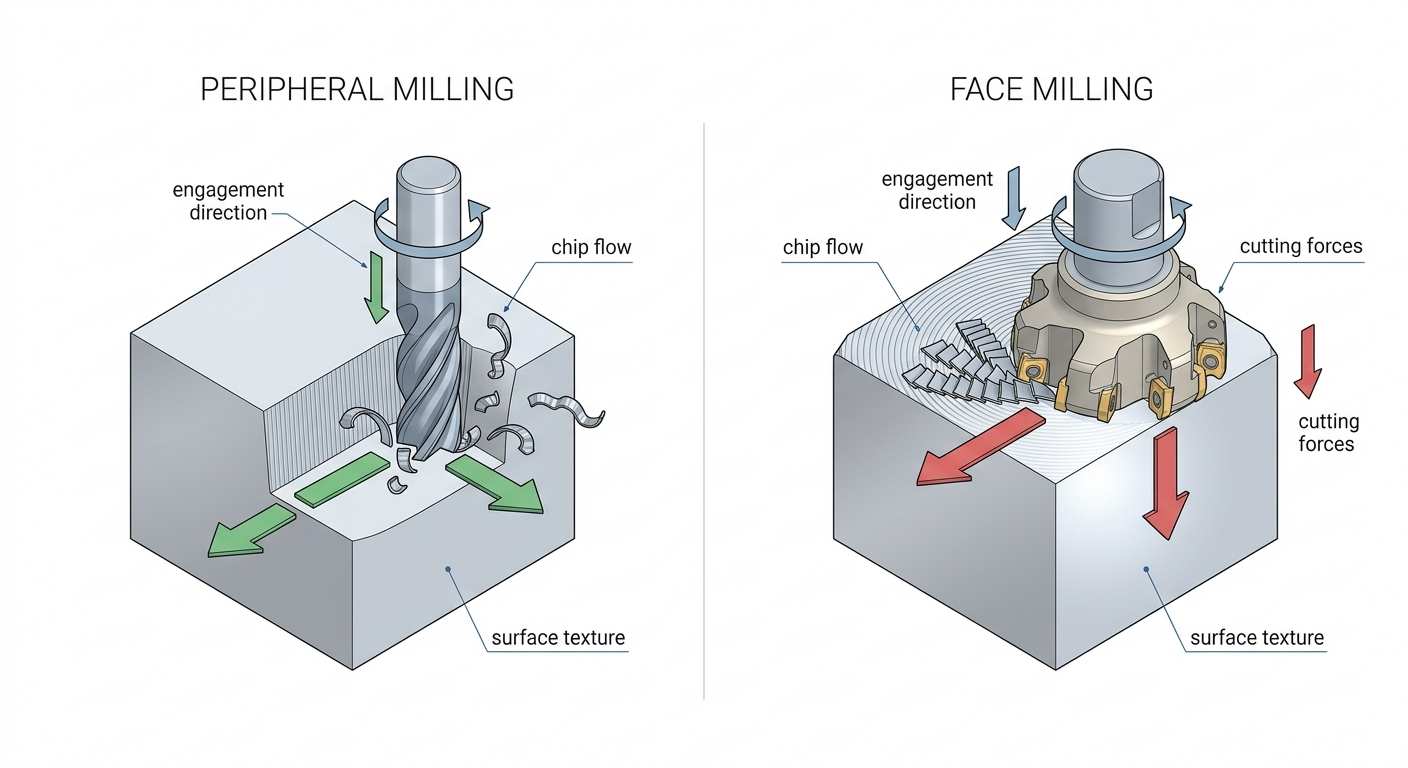
(AI generated) face milling vs peripheral milling
How Peripheral Milling Differs From Face Milling
Peripheral milling and face milling may run on the same CNC machine, but the cutting mechanics change significantly once the cutter engages material. The direction of cutter engagement affects force distribution, chip formation, tool deflection, heat concentration, surface texture, and machining stability. These differences directly influence dimensional accuracy, tool life, and process reliability in production environments.
Cutter Engagement and Force Direction
In peripheral milling operation, the cutting edges along the outside diameter of the cutter generate the finished surface. The cutter axis stays parallel to the machined wall or feature instead of perpendicular like face milling.
That changes force direction immediately.
In peripheral milling, cutting forces act primarily sideways against the tool and workpiece because the cutter engages along its outer diameter. This radial loading increases tool deflection, especially during deep wall machining or long-reach operations. Face milling behaves differently because most cutting force is directed downward into the machine structure, which generally improves setup stability.
This becomes obvious during deep wall machining.
A 12 mm end mill with 70 mm stickout behaves far less stable than the same tool at 20 mm overhang because rigidity drops rapidly as leverage increases.
Surface Finish and Tool-Mark Formation
The surface patterns left behind by these operations reveal how the cutter interacts with the material.
Face milling creates overlapping circular or arc-shaped insert marks across the surface. Under stable cutting conditions, the finish appears uniform and consistent. Wiper inserts can flatten peak height further, producing finishes that approach grinding quality on rigid setups.
Peripheral milling leaves directional linear tool marks that follow the cutter path. The side of the cutter directly generates the finished wall surface as the tool moves through the cut.
In peripheral milling, surface finish and dimensional accuracy are closely connected because the side cutting edge directly generates the wall geometry. Even slight tool deflection can shift wall dimensions or create taper on deep features. Thin-wall parts are especially sensitive because both the cutter and the workpiece may flex during machining.
This becomes more noticeable on aerospace ribs, deep pockets, and thin aluminum structures where radial cutting forces continuously push against unsupported material.
Light finishing passes are commonly used to reduce cutting force and improve dimensional consistency on precision walls and pockets.
Burr formation also differs between the two operations. Peripheral milling generally produces more edge burrs because the side cutting edge exits the material along the wall boundary, especially in stainless steel and ductile aluminum alloys.
Chip Formation and Material Removal Behavior
Chip behavior changes considerably between face milling and peripheral milling because cutter engagement conditions are different.
Face milling usually produces shorter and freer-flowing chips because inserts repeatedly enter and exit the material. This intermittent engagement improves cooling and allows chips to evacuate more easily from the cutting zone.
Peripheral milling often traps chips longer, especially during slotting, deep pockets, and high axial engagement cuts.
A full-width slot cut is one of the most demanding examples. Chips become confined around the cutter while heat continues building near the cutting edge. Recutting those chips damages surface finish, increases cutting pressure, and accelerates flank wear simultaneously.
Excessive heat often appears as dark blue or straw-colored chips, especially during full-width slotting in harder alloys.
This is one reason modern high-efficiency milling strategies avoid large radial engagement whenever possible. Instead of burying most of the cutter diameter into the material, adaptive toolpaths often use lower radial engagement with deeper axial cuts and higher feed rates.
Lower engagement reduces average cutting force, improves chip evacuation, and keeps more heat inside the chips rather than the cutting tool itself.
Material behavior also changes the cutting response. Aluminum usually struggles more with chip packing and edge welding at high temperatures. Stainless steel generates higher heat concentration and work hardening, while titanium retains heat near the cutting zone and increases tool wear rapidly under unstable engagement conditions.
Machining Stability and Tool Deflection
Peripheral milling exposes rigidity problems quickly because the cutter experiences continuous side loading throughout the operation.
Every increase in tool overhang reduces stiffness significantly. Deflection rises rapidly as leverage increases, which is why long-reach tools become unstable much faster under the same cutting conditions.
Shorter tool setups generally improve stability more effectively than simply reducing spindle speed or feed rate.
Machine rigidity and workholding quality strongly influence peripheral milling stability. Horizontal machining centers generally resist radial cutting loads better than lighter vertical machines, especially during deep wall or high-engagement cuts.
Poorly supported parts amplify vibration quickly under side loading, leading to chatter, accelerated insert wear, and inconsistent surface finish.
Tool-Mark Direction and Surface Texture
Tool-mark direction affects more than cosmetic appearance. Surface texture orientation changes how machined parts behave during assembly and service.
Face milled surfaces typically show multidirectional arc patterns created by overlapping insert paths. Peripheral milling produces directional linear textures that follow feed motion along the wall or contour.
This difference influences lubrication retention, sealing performance, paint adhesion, friction behavior, and reflected surface appearance.
Sliding components, sealing faces, and cosmetic aluminum parts often respond differently depending on texture orientation, even when measured roughness values appear similar.
On consumer electronics housings and machined covers, two surfaces may share nearly identical Ra values while still looking visibly different under inspection lighting because the cutter path direction changed.
That difference comes directly from how face milling and peripheral milling generate the surface geometry itself.
For production CNC parts, selecting the wrong milling strategy often leads to unnecessary finishing work, unstable wall dimensions, or inconsistent surface appearance across batches. JLCCNC supports project-specific milling process selection for aluminum, stainless steel, and titanium components where surface quality, rigidity, and machining stability must be balanced together.

Precision CNC Machining Service
Professional manufacturing, fast turnaround, and quality assurance.
Cutting Tools and Machine Setup for Peripheral Milling
(AI generated) carbide slab mills side mills and end mills
Peripheral milling performance depends heavily on tool geometry and setup rigidity because the cutter side is constantly carrying cutting load. That's a tougher environment than many face milling operations, especially once depths increase or wall tolerances tighten.
A setup that feels perfectly stable during light surfacing can become unpredictable once a long side-cutting tool starts engaging material at full axial depth.
Not in CAM. Not in spindle horsepower. In the physical mechanics of the setup itself.
Slab Mills, Side Mills, and End Mills
Different peripheral milling cutters exist because different geometries load the machine differently.
Slab mills are large cylindrical cutters traditionally used on horizontal mills for machining broad flat surfaces with high material removal rates. They're extremely rigid because the arbor supports the cutter across its width rather than only at the spindle taper.
That support matters.
A horizontal slab mill removing steel at 8-12 mm depth behaves far more stable than a small end mill attempting the same engagement unsupported. Old-school horizontal milling setups still outperform many modern VMCs for heavy roughing because the cutter structure itself is fundamentally stronger.
Side mills add cutting teeth along the side and face simultaneously, making them useful for slots, shoulders, and paired-wall features. Straddle milling setups often use matched side cutters to machine parallel faces in one pass with very consistent spacing.
Then there's the end mill, basically the workhorse of modern CNC peripheral milling.
Solid carbide end mills handle everything from roughing to finishing to high-speed adaptive machining. Four-flute tools balance rigidity and chip evacuation for steels. Three-flute and variable-helix tools dominate aluminum machining because they clear chips better at high spindle speeds.
Variable helix geometry helped solve a major milling problem over the last decade: harmonic chatter.
When all flutes engage the material at identical spacing, vibration frequencies stack consistently. Varying flute spacing breaks up those harmonics and stabilizes the cut. It's one of those subtle tool design improvements that quietly changed machining performance everywhere.
Horizontal vs Vertical Milling Configurations
Horizontal milling machines generally handle aggressive peripheral milling more effectively because the spindle orientation improves rigidity during side cutting and helps chips evacuate naturally from deep features. Arbor-supported cutters on horizontal systems also resist radial cutting forces better during heavy roughing operations.
Vertical machining centers remain more flexible for general CNC work and handle most peripheral milling operations well, especially for smaller parts and moderate cutting depths. However, long-reach end mills in vertical setups usually reach rigidity limits sooner under heavy side loading.
For a broader comparison of machine structure, chip evacuation, and machining applications, see our guide on vertical vs horizontal CNC machining.
Tool Overhang and Cutter Rigidity
Tool overhang has a major influence on peripheral milling stability because side cutting forces continuously load the cutter laterally. Even small increases in stickout reduce rigidity significantly and increase the risk of chatter, tool deflection, and inconsistent wall finish.
A short carbide end mill may cut steel stably at aggressive feed rates, while the same tool with excessive overhang can lose dimensional accuracy under identical cutting conditions. Reducing tool stickout is often more effective than adjusting spindle speed or feed rate alone.
Holder rigidity also affects stability under radial cutting loads. Hydraulic and shrink-fit holders generally provide better damping and stiffness than standard collet systems during aggressive peripheral milling operations.
Conventional vs Climb Milling Strategy
Feed direction changes cutting behavior significantly in peripheral milling. In conventional milling, the tooth enters the cut at low chip thickness and exits at maximum thickness, which increases rubbing and heat generation. Climb milling reverses this pattern, allowing cleaner shearing action, lower cutting forces, and better surface finish under rigid CNC conditions.
Modern CNC machining generally favors climb milling because it improves tool life and machining stability during side cutting operations. Conventional milling may still be used on scaled surfaces, unstable setups, or older machines with backlash concerns.
For a more detailed comparison of cutting mechanics, chip formation, and machining applications, see our guide on climb milling vs conventional milling.
Common Machining Problems in Peripheral Milling
| Problem | What Causes It | What Happens |
|---|---|---|
| Chatter and Vibration | Long tool overhang, unstable radial cutting forces, poor rigidity | Wavy surface finish, loud cutting noise, shortened tool life |
| Tool Wear and Edge Breakdown | High heat, chip recutting, excessive cutter engagement | Chipped cutting edges, loss of dimensional accuracy, sudden tool failure |
| Poor Surface Finish and Burr Formation | Dull tooling, unstable feed rates, improper climb/conventional milling setup | Rough walls, heavy burrs, inconsistent edge quality |
| Dimensional Errors in Deep or Thin Features | Tool deflection and part flex under side-cutting loads | Undersized pockets, tapered walls, warped thin sections |
When to Use Peripheral Milling vs Face Milling
Machining Flat Surfaces vs Side Walls
Face milling is usually the better choice for large flat surfaces because the cutter face generates smoother finishes with better stability. Peripheral milling works better for walls, slots, contours, pockets, and deep side features where the cutter needs side access.
Rough Material Removal vs Finish Surface Machining
Face milling removes large amounts of surface material efficiently during roughing and surfacing operations. Peripheral milling becomes more useful when geometry gets more detailed or when side-wall accuracy matters more than flatness.
Thin-Wall Features and Deflection Sensitivity
Thin walls generally tolerate face milling forces better because most cutting load pushes downward into the setup. Peripheral milling applies stronger radial forces, which can bend thin sections or pull long tools off position if parameters are too aggressive.
Machine Configuration and Tool Accessibility
Horizontal machines naturally suit many peripheral milling operations because chip evacuation improves during side cutting. Vertical machining centers handle face milling very efficiently and provide easier setup access for flat-part machining. Tool reach, spindle rigidity, and workholding access often decide which strategy works best in real production.
Conclusion About Peripheral Milling
Peripheral milling and face milling may happen on the same CNC machine, but they behave very differently once the cutter touches material. The direction of cutter engagement changes cutting forces, chip flow, heat concentration, tool deflection, and final surface quality.
Face milling usually delivers better stability for large flat surfaces. Peripheral milling gives better access to walls, slots, contours, and detailed geometry. Neither operation is universally “better.” The right choice depends on part geometry, rigidity, surface finish requirements, and how the cutting forces interact with the setup.
That’s why successful CNC machining is rarely about memorizing operation names. It’s about understanding how the cutter behaves under load and choosing the milling strategy that keeps the process stable, repeatable, and efficient.
At JLCCNC, we help manufacturers choose the right milling strategy for complex CNC parts, from high-speed aluminum machining to tight-tolerance steel and titanium components. Upload your CAD files to get engineering feedback and a fast manufacturing quote for custom CNC machining projects.
Precision CNC Machining Service
Professional manufacturing, fast turnaround, and quality assurance.
FAQ About Peripheral Milling
Q: What is peripheral milling in CNC machining?
Peripheral milling is a milling process where material is removed mainly by the cutter’s outer circumference rather than the tool face.
Q: Why does peripheral milling cause taper in deep walls?
Deep wall taper usually happens because radial cutting forces deflect the tool during side engagement. The longer the tool overhang and the deeper the wall, the more the cutter bends away from the programmed toolpath. Thin workpieces can also flex under cutting pressure, increasing dimensional variation.
Q: Can face milling replace peripheral milling in pocket finishing?
Not completely. Face milling can efficiently remove material from open flat areas, but pocket walls and vertical features still require peripheral cutting to generate accurate side geometry. Many CNC machining operations combine both strategies in the same setup.
Q: Which cutters are used for peripheral milling?
End mills, slab mills, side mills, slot cutters, and profile cutters are commonly used for peripheral milling operations.
Q: Is slot milling considered peripheral milling?
Yes, slot milling is a type of peripheral milling because the cutter removes material using its outer cutting edges.
Q: Why does peripheral milling create higher radial cutting forces?
Because the cutter engages along its diameter, cutting forces push sideways against the tool and workpiece rather than downward into the machine table.
Q: When is peripheral milling preferred over face milling?
Peripheral milling is preferred for machining slots, side walls, contours, pockets, and deep features that face mills cannot access effectively.
Q: Which produces better surface finish, face milling or peripheral milling?
Face milling usually produces smoother large flat surfaces, while peripheral milling produces better finishes on walls, slots, and detailed contours.
Popular Articles
• Cutting with Precision: A Comprehensive Guide to CNC Water Jet Technology
• CNC Coolant Explained: Types, Maintenance & Safety
• Rake Angle in Machining: Machinists’ Guide to Perfect Cuts
• What Steps Are Taken To Minimize Waste In CNC Machining Processes?
• How EDM Wire Cutting Works: Complete Guide to Precision CNC Wire Cutting
Keep Learning
Chatter in Machining: Causes, Effects, and How to Reduce It
CNC milling operation producing visible chatter marks on an aluminum workpiece Quick Chatter Diagnosis Checklist Symptom Most Likely Cause First Action High-pitched squeal Regenerative chatter Change spindle speed ±15% Chatter only in deep pockets Excessive tool overhang Shorten tool Chatter on thin walls Low workpiece rigidity Improve fixturing Chatter after tool replacement Runout / holder issue Check tool holder Chatter only during finishing DOC too small / rubbing Increase feed or adjust speed It ......
What Is Tool Offset in CNC? Types, Setup & Best Practices
CNC tool offset setup with measurement overlay Key Takeaways CNC offsets connect programmed intent with actual cutter position. Length data guides Z-axis depth control. Radius data protects part size during contour milling. Geometry values define the cutter's measured baseline. Wear values support fine correction during production. Verified data lowers scrap risk before full machining. Good offset habits protect tools, fixtures, and parts. In the context of CNC machining , tool offset is the quiet set......
Trochoidal Milling: Complete Guide to High-Efficiency CNC Machining
Key Takeaways Trochoidal milling combines circular cutter motion with continuous forward feed. The cutter normally engages 5 to 20% of its diameter instead of making a full-width cut. A smaller engagement angle limits force changes during slotting and pocket roughing. Low radial engagement often allows greater axial depths of cut than conventional slot milling. CAM software calculates the circular path automatically from the selected machining parameters. This strategy is widely applied to titanium, s......
What Is Die Casting? Process, Materials, and Applications
Key Takeaways Die casting is a metal casting process that forces molten metal into a reusable steel mold under high pressure, producing parts with tight tolerances and good surface finish at high volume. Aluminum die casting is the most common form by far, thanks to its combination of light weight, decent strength, and good corrosion resistance. The die casting process runs through mold preparation, injection, cooling, and ejection in a cycle that can repeat every few seconds to minutes depending on p......
First Angle vs Third Angle: Understanding Orthographic Projection Methods
Key Takeaways Orthographic projection is the system that lets a 3D part be represented through multiple 2D views, front, top, side, and so on. First angle projection and third angle projection are the two standard methods for arranging those views, and they place views in opposite positions relative to the object. First angle projection is the ISO standard used across most of Europe, India, China, Russia, and many other countries following ISO standards Third angle projection is the standard in the Un......
Micro EDM Machining: Capabilities, Materials, and Applications for Precision Components
Key Takeaways About Micro EDM Machining Only electrically conductive materials can be machined. Hole diameters can reach below 50 μm on specialized equipment. The process produces almost no mechanical cutting force, making it suitable for thin or delicate features. Surface integrity still requires attention because recast layers and heat-affected zones may remain after machining. Micro EDM is often combined with CNC machining, with milling producing the main geometry before EDM finishes critical micro......