Form Milling: Process, Cutters, Types, Benefits, and Applications
24 min
- What Is Form Milling?
- Form Milling at a Glance
- How Does the Form Milling Process Work?
- How Does Form Milling Compare with Other Milling Operations?
- What Are Form Milling Cutters?
- What Are the Main Types of Form Milling Cutters?
- Limitations and Benefits of Form Milling
- What Materials Are Used for Form Milling Cutters?
- What Are the Main Applications and Uses of Form Milling?
- When to Use Form Milling (and When Not To)
- Form Milling Services for Custom CNC Machined Parts
- How to Choose the Best Form Milling Cutter?
- What Factors Affect Form Milling Quality?
- FAQ about the Form Milling
Key Takeaways
• Form milling uses a profile-specific cutter to machine complex contours in a direct profile transfer.
• Form milling cutters directly transfer their geometry onto the workpiece, improving repeatability.
• Common types of form milling cutters include concave, convex, corner rounding, and gear cutters.
• The form milling process is highly efficient for repeated profiles in high-volume production.
• Carbide form milling cutters provide better wear resistance and profile stability than HSS tools.
• Applications of form milling include gears, splines, grooves, radii, and custom contours.
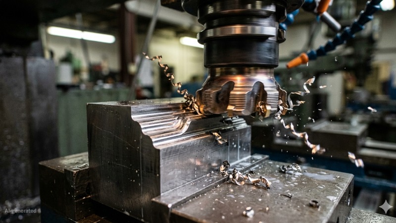
(AI generated) form milling cutter creating a profiled contour
Form milling is how you machine a specific profile without building it through toolpath movement. The cutter already has the shape, it transfers directly onto the part in a single pass. That makes it efficient for repeatable geometry like grooves, contours, and complex edges where the same profile appears across multiple parts.
What Is Form Milling?
In most milling operations, geometry is created through tool movement. The machine follows a programmed path, and the final shape is built gradually over multiple passes.
Form milling works differently. The geometry is already built into the cutter. As the tool rotates and feeds into the workpiece, that profile transfers directly onto the part surface in a single operation. This makes the process highly efficient for repeated features such as grooves, radii, gear teeth, and custom contours.
Because the profile comes from the cutter itself, repeatability is extremely high once the correct tool is selected. The tradeoff is lower flexibility. Each geometry requires a dedicated cutter, which is why form milling is most effective in medium- to high-volume production where the same feature is repeated across many parts.
The comparison to end milling or face milling, the difference is simple: traditional milling generates geometry through machine movement, while form milling generates geometry directly from the cutter profile. This allows faster production of identical contours with consistent dimensional accuracy.
Form Milling at a Glance
| Factor | Form Milling |
|---|---|
| Main purpose | Machine repeatable profiles |
| Geometry source | Cutter profile |
| Best for | Grooves, radii, gears |
| Production volume | Medium to high |
| Flexibility | Low |
| Surface finish | High consistency |
| Typical cutter materials | HSS, Carbide |
How Does the Form Milling Process Work?
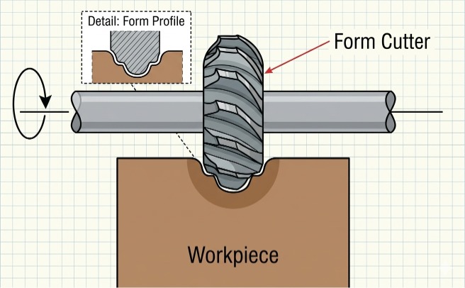
(AI generated) Technical diagram showing a form milling cutter mounted on a horizontal arbor
Form milling isn't complicated to understand, but it rewards attention to setup details that other milling operations let you get away with ignoring.
Basic Steps in the Form Milling Process
The process begins with selecting the correct form milling cutter for the required profile. Unlike end milling, the geometry cannot be adjusted through toolpath compensation. The cutter profile must already match the final shape.
Next, the workpiece is securely fixtured and aligned. Proper positioning is critical because any setup error transfers directly into the machined profile.
Cutting depth and machining parameters are then set according to material type and profile geometry. In many applications, the full contour can be machined in one or two passes. Roughing passes may remove bulk material first, leaving a small allowance for finishing.
During machining, the rotating cutter feeds across the workpiece while transferring its profile directly onto the surface. After machining, the part is typically inspected using gauges, templates, or CMM systems depending on tolerance requirements.
How the Cutter Profile Shapes the Workpiece
In form milling, the entire cutter profile engages the workpiece at the same time. This creates higher cutting forces compared with standard end milling, especially when machining deeper or more complex profiles.
Because different sections of the cutter operate at different cutting conditions, heat and wear are not evenly distributed across the tool. Outer cutting edges usually wear faster than inner sections, which is why periodic inspection and resharpening are important for maintaining profile accuracy.
When the cutter is properly ground and aligned, the machined surface becomes a direct copy of the cutter geometry. Any error or wear on the cutter transfers directly to the finished part.
Key Factors That Affect Form Milling Accuracy
Cutter geometry and condition. Cutter accuracy is the foundation of form milling quality. Worn or damaged cutters gradually change the machined profile, especially in long production runs.
Setup and workpiece positioning. Proper fixturing, arbor alignment, and machine rigidity are essential. Excessive runout or vibration can reduce profile accuracy and surface finish consistency.
For manufacturers producing custom brackets, housings, grooves, or profiled metal components, precision setup becomes especially important in batch production. JLCCNC provides CNC machining and sheet metal fabrication services for custom industrial parts, supporting repeatable machining quality across

Precision CNC Machining Service
Professional manufacturing, fast turnaround, and quality assurance.
Feed rate and cutting speed. Cutting parameters affect both surface finish and tool life. Higher feed rates increase cutting forces, while excessive cutting speed accelerates tool wear. Stable cutting conditions help maintain consistent profile quality.
Material behavior and chip control Softer materials such as aluminum machine more easily, while harder steels generate higher cutting forces and increase wear. Effective coolant flow and chip evacuation help improve surface finish and reduce heat buildup.
How Does Form Milling Compare with Other Milling Operations?
| Comparison Factor | Form Milling | Plain Milling | End Milling |
|---|---|---|---|
| Cutter design | Profile-specific cutter (shape built into tool) | Straight or helical cylindrical cutter | Flat or ball-nose tool |
| Shape generation | Directly from cutter profile | Generated by tool movement (flat surfaces) | Generated by toolpath (complex geometry) |
| Machining capability | Complex contours in one pass | Large flat surfaces | Slots, pockets, 3D contours |
| Flexibility | Low (each profile needs a dedicated cutter) | Medium (limited to flat geometry) | High (handles varied geometries) |
| Setup complexity | Low once cutter is available | Low | Medium to high (programming required) |
| Efficiency | Very high for repeated profiles | High for flat surfaces | Lower for large surfaces, higher for complex parts |
| Typical applications | Gears, grooves, rounded edges, custom profiles | Base plates, flat faces | Cavities, slots, molds, complex parts |
| When it’s the better choice | High-volume production of identical profiles | Wide flat surface machining | Complex or multi-feature parts |
What Are Form Milling Cutters?
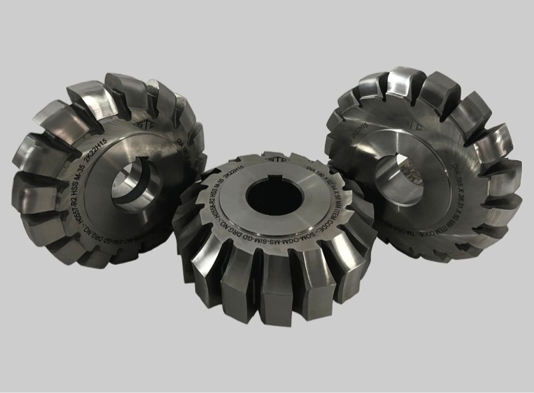
(STC gear cutting tools) Form milling cutters
Most cutting tools are general purpose. Here’s a guide on how to choose the best CNC tools.
A form milling cutter is the opposite, it exists for one geometry, produces that geometry repeatedly, and has no other job. That specificity is both its strength and the thing that makes getting it wrong expensive.
Structure and Working Principle of Form Milling Cutters
A form milling cutter is a rotary cutting tool with teeth ground to a specific profile around its circumference. When the cutter rotates and feeds into the workpiece, that profile transfers directly onto the part surface. The machine controls the cutting motion, while the cutter geometry defines the final profile.
The body is typically HSS or carbide, HSS for general production in softer materials where resharpening cost matters, carbide for harder materials, higher speeds, or applications where tool life between regrinds needs to be longer. Carbide form cutters run at 3–5x the surface speed of HSS equivalents in steel and hold their profile geometry longer under abrasive cutting conditions, but they cost significantly more upfront and are less forgiving of setup errors or interrupted cuts.
Teeth are relieved behind the cutting edge, the relief angle clears the workpiece after each tooth passes, preventing rubbing and allowing the next tooth to engage cleanly. Relief geometry on form cutters is more complex than on flat-profile tools because the relief must follow the profile contour without undercutting it. A poorly relieved form cutter either rubs the workpiece on the trailing face, generating heat and poor finish, or cuts incorrectly on the profile flanks. Getting relief geometry right is part of what makes form cutter grinding a specialized skill rather than a standard resharpening operation.
Tooth count varies with cutter diameter and application. Coarse-tooth cutters, 4 to 6 teeth on a 50–75mm diameter cutter, handle heavier cuts and clear chips more easily in deeper profiles. Fine-tooth cutters carry more teeth for better surface finish at the cost of chip clearance, suited to finishing passes in shallower profiles or softer materials.
The cutter mounts on an arbor for horizontal milling or directly in a spindle for vertical applications. Arbor mounting is more common in traditional form milling because the supported setup reduces deflection under the higher cutting forces that full-profile engagement generates.
Why Cutter Geometry Is Critical in Form Milling
The main difference in form milling is that almost every other machining operation: the cutter is the tolerance. In end milling, if the radius is slightly wrong, you adjust the toolpath offset and re-cut. In form milling, the profile in the cutter is the profile in the part. There is no correction that doesn't involve a different or reground cutter.
That creates a chain of dependency that runs from cutter design through grinding through inspection through the machined part. Each step in that chain can introduce error, and those errors compound.
A real example illustrates this well. In turbine blade root machining, one of the highest-precision form milling applications in production engineering, fir-tree root profiles are machined using form cutters ground to tolerances of ±0.005–0.008mm on the profile. The fir-tree geometry interlocks with the disc slot, and contact stress distribution across the root depends on profile accuracy across the full tooth form. A cutter ground 0.015mm out of tolerance on one flank shifts the contact patch, concentrates stress unevenly, and creates a fatigue initiation site in a part that operates at high temperature under cyclic loading. The cutter error doesn't show up as a visible defect, it shows up as a field failure after thousands of flight cycles.
That's an extreme case, but the principle applies at every scale. Automotive camshaft lobe profiles, spline cutters for gearbox shafts, woodruff key seat cutters, T-slot cutters, in every case, the profile ground into the cutter is the first and most important dimension in the tolerance chain.
Cutter Geometry and Surface Quality
Profile accuracy is one dimension of cutter geometry. Surface quality adds another, the rake angle, relief angle, and edge condition of each tooth determine how cleanly material separates and what finish the workpiece surface carries.
Positive rake angles reduce cutting forces and heat generation, which improves surface finish and extends tool life in softer materials. Aluminum and brass form milling typically uses 10–15° positive rake. Steel drops that to 5–10° to preserve edge strength. Hardened materials and interrupted cuts sometimes run negative rake to prevent chipping on brittle carbide edges, negative rake increases cutting force but protects the edge geometry that, in a form cutter, is the profile itself.
Edge sharpness matters more in form milling than in many other operations because a chipped or worn tooth doesn't just reduce tool life, it changes the profile. A single chipped tooth on a radius cutter produces a flat spot in the radius on every subsequent part until the cutter is replaced or reground. In a production run of 500 parts, catching that at part 12 versus part 340 is the difference between a minor interruption and a significant scrap event.
This is why form cutter inspection before and during a run isn't a quality formality, it's process control. Optical comparators, CMM stylus probing of the cutter profile, and surface finish measurement of the first article are standard practice in any shop doing precision form milling at volume. The cutter is inspected because every part it touches carries whatever error the cutter carries, multiplied across the full production run.
What Are the Main Types of Form Milling Cutters?
The main types of form milling cutters are designed for different profile geometries, including internal radii, external contours, rounded corners, gear teeth, and custom shapes.
| Cutter Type | Geometry Produced | Typical Use Case | Selection Logic | Production Suitability |
|---|---|---|---|---|
| Concave cutters | Internal radii (curved inward profiles) | Grooves, fillets, rounded internal features | Choose when the part requires consistent internal curvature with tight radius control | High for repeated curved features |
| Convex cutters | External radii (curved outward profiles) | Rounded edges, external contours | Used when external surfaces need smooth, uniform curvature | High for edge profiling in batches |
| Corner rounding cutters | Rounded corners (fillets on edges) | Edge finishing, stress reduction features | Selected to improve part strength and eliminate sharp edges | Very high in production for consistent edge finishing |
| Gear form cutters | Gear tooth profiles | Spur gears, splines | Chosen based on module, pressure angle, and gear standard | Essential for gear manufacturing in medium to high volumes |
| Custom profile cutters | Any complex or non-standard shape | Specialized components, unique contours | Designed specifically for part geometry when standard cutters cannot achieve the shape | Best for high-volume production to justify tooling cost |
Limitations and Benefits of Form Milling
Form milling earns its place in production through a specific kind of efficiency, not speed in the conventional sense, but the elimination of complexity. Understanding where it delivers and where it doesn't comes down to one question: how many times does that profile need to appear?
Where Form Milling Delivers
The core advantage is that complex profiles cost the same per part whether you're making ten or ten thousand. Once the cutter exists and the setup is dialed in, each part takes one pass. A concave radius that would require multiple contouring passes in end milling, each one requiring toolpath calculation, stepover management, and a finishing pass to clean up the scallops, becomes a single feed move. The machine isn't interpolating geometry. The cutter is transferring it.
In practical terms this compresses cycle time significantly on profile-heavy parts. A woodruff keyway that takes 3–4 minutes to produce by end milling takes under a minute by form milling. A T-slot that requires a two-tool sequence, end mill to open the slot, T-slot cutter to undercut, still requires two tools, but each pass is a single feed move rather than a contouring operation. On a production run of 2,000 gearbox housings, that cycle time difference is the budget.
Repeatability is the other major advantage, and it's worth being specific about what that means mechanically. In contouring operations, part-to-part variation accumulates from toolpath execution, tool deflection, thermal drift in the machine, and wear-induced diameter change in the cutter. Each of those variables contributes to dimensional scatter across a production run. In form milling, most of those variables are removed. The profile comes from the cutter geometry, not from the machine's ability to follow a path accurately. A well-maintained form cutter on a rigid setup produces profiles within ±0.02–0.05mm across hundreds of parts without adjustment, a consistency level that contouring operations struggle to match without in-process measurement and compensation.
For industries where profile consistency directly affects function, splines that must assemble interchangeably, gear tooth forms that affect load distribution, radius features that act as stress relief geometry, that repeatability isn't a convenience. It's a requirement.
Where It Breaks Down
The same specificity that makes form milling efficient in production makes it expensive and inflexible everywhere else.
Tooling cost is the first barrier. A standard end mill costs $15–80 depending on diameter and coating. A custom-ground form cutter for a specific profile runs $200–800 for HSS and $500–2,000+ for carbide, depending on profile complexity and tolerance requirements. That cost is fixed regardless of how many parts you make. At ten parts, the tooling cost per part is $20–200 before a single chip is cut. At 500 parts, it's $0.40–4.00. The process only makes economic sense when volume justifies the tooling investment, and that break-even point varies enough with part complexity and profile tolerance that it needs calculating rather than assuming.
Profile changes are the second problem. In end milling, a design revision means a toolpath update, hours of work at most. In form milling, a profile revision means a new cutter. If the radius changes from 6mm to 7mm midway through a product development cycle, the existing form cutter is scrap. This makes form milling a poor choice for any application still in active design iteration, and a reasonable choice only once the geometry is frozen and production volume is confirmed.
Setup accuracy requirements are tighter than most milling operations and less forgiving when missed. Runout above 0.02mm on the cutter, misalignment between cutter centerline and workpiece datum, or inadequate fixturing rigidity all produce profile errors that can't be corrected after the fact. In contouring, a rigid setup improves results but a slightly less rigid one still produces acceptable geometry with compensation. In form milling, a poor setup produces wrong profiles, consistently, across every part in the run, until someone measures a part and catches it.
Cutter wear adds a time dimension to that problem. Form cutters wear unevenly because different sections of the profile operate at different effective cutting speeds and chip loads. The outer diameter wears faster than the profile center. Over time, the cutter geometry drifts, slowly enough that individual parts look acceptable, fast enough that parts at the end of a long run may be outside tolerance compared to parts at the beginning. Without periodic first-article checks during a run, wear-related drift goes undetected until a downstream assembly or inspection step catches it. Establishing a resharpening interval based on measured profile drift, rather than a fixed number of parts, is better practice and catches problems before they become scrap events.
Finally, material hardness limits the process more sharply than it limits contouring. Full-profile engagement generates cutting forces that scale with material hardness. Above approximately 38–42 HRC in steel, those forces exceed what most form cutter geometries and arbor setups handle without deflection or chipping. Hard turning and grinding take over at that hardness range, and form milling steps aside.
What Materials Are Used for Form Milling Cutters?
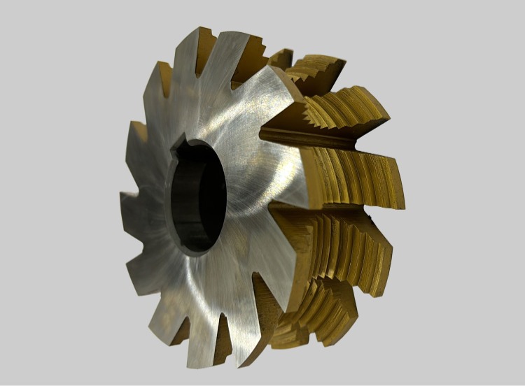
(STC) TiN coated HSS form milling cutter
High-Speed Steel, Carbide, and Other Tool Materials
Most form milling cutters are made from high-speed steel (HSS) or carbide, depending on the application.
HSS is tougher and more forgiving. It handles interrupted cuts and less rigid setups well, which makes it suitable for general-purpose form milling and lower-speed operations.
Carbide is harder and more wear-resistant. It allows higher cutting speeds and maintains edge geometry longer, which is critical in the form milling process where profile accuracy must stay consistent across many parts.
Other variations include coated carbide and specialized alloys, used when machining abrasive materials or running high-volume production.
How Cutter Material Affects Wear Resistance and Performance
Tool material directly affects how long the cutter holds its shape.
In form milling, even slight wear changes the profile. That means dimensional accuracy drops as the cutter degrades. Carbide resists wear better, so it maintains form accuracy over longer production runs.
Cutting speed also changes. Carbide cutters can run 2–4× higher speeds than HSS, which improves productivity. HSS, however, performs better in situations where toughness matters more than speed.
In practice, HSS is chosen for flexibility and lower cost. Carbide is chosen for consistency, higher efficiency, and tighter control in production environments where types of form milling cutters must deliver repeatable geometry.
What Are the Main Applications and Uses of Form Milling?
| Industry / Application | Feature Type | Why Form Milling Is Used | Typical Parts / Examples |
|---|---|---|---|
| Automotive | Gears, splines, grooves | High repeatability and fast production of identical profiles | Transmission gears, shafts, couplings |
| Aerospace | Curved surfaces, precision profiles | Consistent geometry with tight tolerance control | Brackets, structural profiles, turbine-related features |
| Tooling & Die Making | Custom contours, radii, complex edges | Direct shape generation reduces machining steps | Dies, molds, forming tools |
| General Manufacturing | Grooves, fillets, special profiles | Efficient for batch production of repeated shapes | Machine components, fittings |
| Gear Manufacturing | Tooth profiles | Cutter matches gear geometry exactly for accuracy | Spur gears, involute profiles |
| Structural Components | Rounded edges, transitions | Improves stress distribution and surface consistency | Frames, supports, mechanical housings |
This is where the form milling process stands out.
Instead of generating shape through multiple toolpaths, the cutter transfers its profile directly onto the part. That’s why form milling cutters are preferred when the same geometry needs to be repeated across many parts with minimal variation.
In practice, applications of form milling come down to one condition. If the feature has a defined profile and repeats across parts, form milling is usually the fastest and most consistent way to produce it.
When to Use Form Milling (and When Not To)
Form milling is highly effective in the right production environment, but it is not the best solution for every machining application. The process works best when the same profile needs to be repeated consistently across multiple parts.
When Form Milling Is the Better Choice
Form milling is ideal for machining repeated profiles such as grooves, radii, splines, gear teeth, and custom contours. Because the cutter already contains the geometry, the profile can be transferred directly onto the workpiece in a single operation.
This makes the process especially valuable for:
Medium- to high-volume production
Parts with repeated contour features
Applications requiring strong profile consistency
Production environments focused on cycle time reduction
In industries such as automotive, aerospace, tooling, and industrial equipment manufacturing, form milling is commonly used to improve repeatability while reducing machining time.
When Form Milling May Not Be the Best Option
Form milling is less suitable for low-volume production or projects with frequent design changes. Each profile requires a dedicated cutter, so even small geometry revisions may require an entirely new tool.
Compared with end milling, the process is also less flexible for prototype development and iterative design work. If the part geometry changes frequently, programmable toolpath-based machining is usually more economical.
The process can also become more difficult when machining hardened materials, where cutting forces and tool wear increase significantly.
Understanding the Break-Even Point
The biggest tradeoff in form milling is tooling investment versus production efficiency.
Standard end milling offers lower upfront tooling cost and greater flexibility, while form milling reduces cycle time and improves consistency once production volume increases.
For small batches, dedicated form milling cutters may not be cost-effective. However, in larger production runs, the faster machining cycle and reduced variation often offset the higher tooling expense.
Form Milling Services for Custom CNC Machined Parts
Form milling is highly effective for producing repeated contours, grooves, radii, and custom profiles, but achieving stable results depends heavily on tooling quality, machine rigidity, and setup accuracy. In many production environments, maintaining consistent profile accuracy across batch runs is more challenging than the cutting process itself.
When to Use Professional Form Milling Services
Professional CNC machining services become especially valuable when parts require:
Tight profile tolerances
Consistent repeatability across production batches
Custom cutter selection or tooling support
Complex contours combined with other CNC machining operations
Faster turnaround for production-ready components
For low-volume prototyping, standard end milling may be sufficient. However, once production scales or profile consistency becomes critical, specialized form milling capability can significantly improve efficiency and dimensional stability.
Why In-House Form Milling Can Be Difficult
Unlike standard CNC milling, form milling depends on dedicated tooling and highly controlled setup conditions. Even small issues such as cutter runout, machine vibration, or fixture instability can directly affect the final geometry.
Many smaller workshops also lack:
Custom form cutter support
Stable high-rigidity machining setups
In-process inspection capability
Experience managing profile wear across long production runs
Because the cutter itself defines the geometry, maintaining profile accuracy requires both machining experience and process control.
Advantages of Outsourcing Form Milling Parts
Outsourcing form milling can reduce tooling investment, setup complexity, and production risk, especially for custom industrial components or medium-volume manufacturing projects.
A qualified CNC machining supplier can help:
Optimize machining strategy
Improve profile consistency
Reduce production lead time
Support both prototyping and batch production
Combine CNC machining with secondary fabrication processes
For example, JLCCNC
provides custom CNC machining and sheet metal fabrication services for industrial parts requiring precision contours, grooves, edge profiles, and repeatable production quality. The platform supports online quoting, DFM review, rapid prototyping, and scalable manufacturing across aluminum, stainless steel, carbon steel, brass, and engineering plastics.
Precision CNC Machining Service
Professional manufacturing, fast turnaround, and quality assurance.
Choosing the Right CNC Machining Partner
When selecting a supplier for form milled components, it is important to evaluate:
CNC machine rigidity and precision
Experience with profile machining
Cutter and tooling capability
Material support
Quality inspection process
Production scalability
For projects involving custom machined parts, uploading CAD files for manufacturability review and instant quotation can help identify the most efficient production approach before machining begins.
How to Choose the Best Form Milling Cutter?
Selection Based on Part Geometry and Feature Profile
Start with the profile. In the form milling process, the cutter defines the shape, so geometry is the first constraint.
If the part requires a standard radius, groove, or gear profile, select from existing types of form milling cutters. For non-standard contours, a custom cutter is required. That adds upfront cost but ensures the geometry is produced in a full-profile cutting with high repeatability.
Complexity also matters. Sharper transitions and tighter radii demand higher cutter precision. Any deviation in the cutter transfers directly to the part
Selection Based on Material, Accuracy, and Production Volume
Material affects both cutter material and geometry. Harder materials require carbide cutters for wear resistance, while softer materials can be machined with HSS.
Accuracy requirements define tool quality. High-precision parts need tightly ground cutters that maintain profile over time. In high-volume runs, wear becomes critical. Carbide is preferred because it holds shape longer.
Production volume drives the decision. For small batches, standard cutters keep cost low. For large runs, custom form milling cutters improve efficiency and reduce cycle time enough to justify tooling investment.
What Factors Affect Form Milling Quality?
Cutter Accuracy, Tool Wear, and Machine Stability
In form milling, the cutter is the geometry. If the cutter is inaccurate or worn, every part will carry that error.
Tool wear gradually distorts the profile. Even small wear can push parts out of tolerance. Machine stability adds another layer. Vibration or deflection changes how the cutter engages, affecting consistency across the surface.
Cutting Parameters and Surface Finish Control
Cutting speed, feed rate, and depth of cut influence both finish and accuracy.
Higher speeds improve productivity but accelerate wear. Higher feed increases cutting force, which can distort the profile if the setup isn’t rigid.
Surface finish is tied to feed per tooth and cutter geometry. A stable setup with proper parameters maintains both finish and dimensional accuracy across repeated parts.
FAQ about the Form Milling
Q: What is form milling?
Form milling is a machining process where a specially shaped cutter produces a specific profile or contour on a workpiece in a single pass.
Q: How does the form milling process work?
The cutter rotates and feeds into the material, transferring its pre-defined shape directly onto the part without needing complex toolpaths.
Q: What are form milling cutters?
Form milling cutters are profile-specific cutting tools designed with a geometry that matches the desired shape to be machined.
Q: What are the main types of form milling cutters?
Common types include concave cutters, convex cutters, corner rounding cutters, gear cutters, and custom profile cutters.
Q: What is form milling used for?
Form milling is used to produce repeated profiles such as gears, grooves, radii, and complex contours in high-efficiency production environments.
Popular Articles
• Cutting with Precision: A Comprehensive Guide to CNC Water Jet Technology
• CNC Coolant Explained: Types, Maintenance & Safety
• Rake Angle in Machining: Machinists’ Guide to Perfect Cuts
• What Steps Are Taken To Minimize Waste In CNC Machining Processes?
• How EDM Wire Cutting Works: Complete Guide to Precision CNC Wire Cutting
Keep Learning
Chatter in Machining: Causes, Effects, and How to Reduce It
CNC milling operation producing visible chatter marks on an aluminum workpiece Quick Chatter Diagnosis Checklist Symptom Most Likely Cause First Action High-pitched squeal Regenerative chatter Change spindle speed ±15% Chatter only in deep pockets Excessive tool overhang Shorten tool Chatter on thin walls Low workpiece rigidity Improve fixturing Chatter after tool replacement Runout / holder issue Check tool holder Chatter only during finishing DOC too small / rubbing Increase feed or adjust speed It ......
What Is Tool Offset in CNC? Types, Setup & Best Practices
CNC tool offset setup with measurement overlay Key Takeaways CNC offsets connect programmed intent with actual cutter position. Length data guides Z-axis depth control. Radius data protects part size during contour milling. Geometry values define the cutter's measured baseline. Wear values support fine correction during production. Verified data lowers scrap risk before full machining. Good offset habits protect tools, fixtures, and parts. In the context of CNC machining, tool offset is the quiet setu......
Trochoidal Milling: Complete Guide to High-Efficiency CNC Machining
Key Takeaways Trochoidal milling combines circular cutter motion with continuous forward feed. The cutter normally engages 5 to 20% of its diameter instead of making a full-width cut. A smaller engagement angle limits force changes during slotting and pocket roughing. Low radial engagement often allows greater axial depths of cut than conventional slot milling. CAM software calculates the circular path automatically from the selected machining parameters. This strategy is widely applied to titanium, s......
What Is Die Casting? Process, Materials, and Applications
Key Takeaways Die casting is a metal casting process that forces molten metal into a reusable steel mold under high pressure, producing parts with tight tolerances and good surface finish at high volume. Aluminum die casting is the most common form by far, thanks to its combination of light weight, decent strength, and good corrosion resistance. The die casting process runs through mold preparation, injection, cooling, and ejection in a cycle that can repeat every few seconds to minutes depending on p......
First Angle vs Third Angle: Understanding Orthographic Projection Methods
Key Takeaways Orthographic projection is the system that lets a 3D part be represented through multiple 2D views, front, top, side, and so on. First angle projection and third angle projection are the two standard methods for arranging those views, and they place views in opposite positions relative to the object. First angle projection is the ISO standard used across most of Europe, India, China, Russia, and many other countries following ISO standards Third angle projection is the standard in the Un......
Micro EDM Machining: Capabilities, Materials, and Applications for Precision Components
Key Takeaways About Micro EDM Machining Only electrically conductive materials can be machined. Hole diameters can reach below 50 μm on specialized equipment. The process produces almost no mechanical cutting force, making it suitable for thin or delicate features. Surface integrity still requires attention because recast layers and heat-affected zones may remain after machining. Micro EDM is often combined with CNC machining, with milling producing the main geometry before EDM finishes critical micro......