Circularity GD&T Explained
18 min
- What Is Circularity in GD&T?
- Circularity Symbol and Drawing Callout
- Circularity Tolerance Zone and Example
- How Is Circularity Measured?
- Circularity vs Cylindricity and Runout
- When to Specify Circularity
- Circularity GD&T FAQs
- Conclusion About Circularity GD&T
Key Takeaways
- Circularity controls how round each cross-section is on a cylindrical, conical, or spherical surface.
- Each cross-section is checked separately. Circularity doesn't control taper, axis straightness, or alignment between sections.
- No datum is needed because circularity controls the shape of the feature itself.
- The circularity tolerance zone is bounded by two concentric circles whose radial separation equals the specified tolerance. Each circular element must fit within its own zone, evaluated independently of other cross-sections.
A shaft can meet its diameter tolerance and still have a roundness problem. The same goes for a bore or bearing race. If the surface is slightly uneven around its circumference, the part may not fit or rotate as intended. The effect depends on how the component is used and which surfaces need to make contact.
Circularity GD&T controls the roundness of individual cross-sections. It doesn't control the diameter itself, or tell you whether the feature sits in the right position. Those are separate requirements, covered by other tolerances.
Below, we'll break down how circularity is shown on a drawing, what the tolerance actually controls, and how you can inspect it. We'll also compare it with cylindricity and runout, since these controls can seem similar but serve different purposes.
Standards Scope
Unless noted otherwise, the drawing examples in this guide follow ASME Y14.5-2018(R2024). ISO GPS drawings must be interpreted using the ISO standards and modifiers specified on the drawing, because size-envelope and verification rules are not automatically interchangeable between ASME and ISO systems.
What Is Circularity in GD&T?
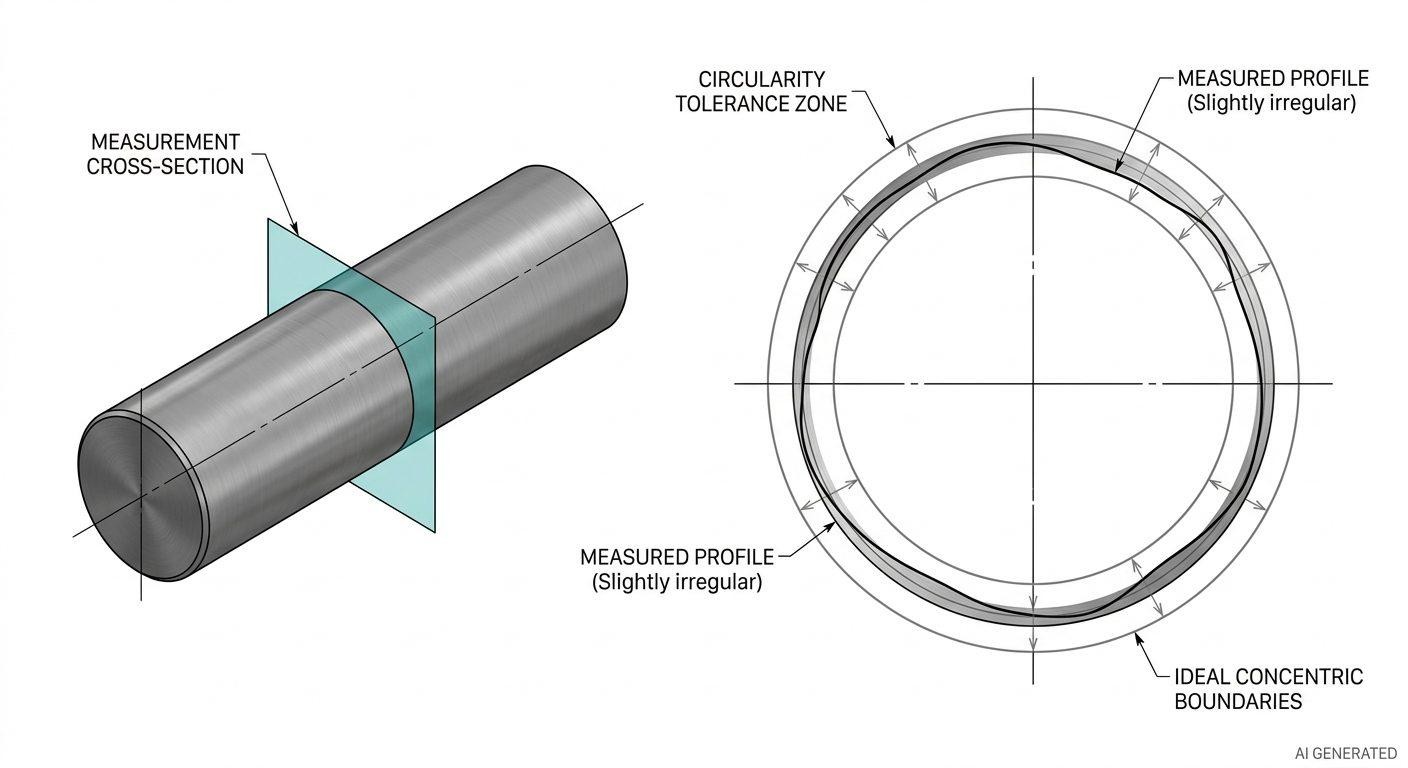
Circularity tolerance shown on a shaft cross-section
Circularity as a Form Tolerance
Circularity belongs to the form tolerances in GD&T. Like straightness, flatness, and cylindricity, it controls the shape of a feature without using a datum as a reference. The tolerance zone is based on the feature itself, not its location or orientation relative to another part.
Take a cylindrical shaft. Its diameter might be within tolerance, but that alone doesn't tell you how round the cross-section is. A section could have slight high and low spots around its circumference. Circularity limits those variations by requiring the entire cross-section to lie between two concentric circles. The distance between the circles is the specified tolerance. Each section is evaluated on its own.
Here's where circularity has a limit. Checking the cross-sections tells you about their roundness, but not how they line up along the shaft. A shaft could have round cross-sections and still bend along its length. Its diameter could also change from one end to the other. Neither issue is fully addressed by circularity. Depending on the drawing, you may need a straightness control, a size tolerance, or runout to deal with those other requirements.
Circularity is useful when you need to restrict local roundness without tying that requirement to a datum. If the concern extends to the full cylindrical surface or how the part runs relative to another feature, you'll need to look at other controls too.
Features Controlled by Circularity
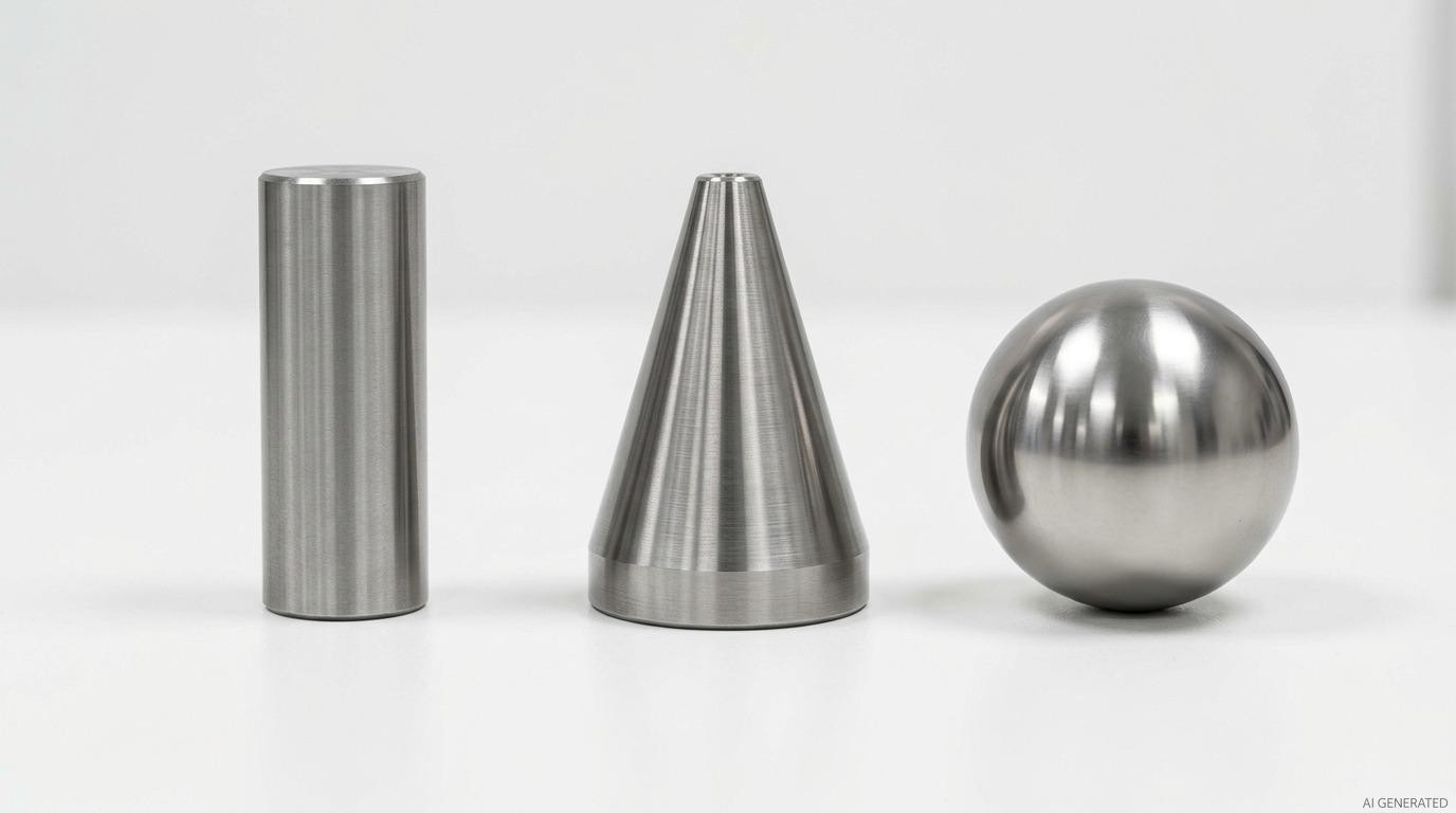
Cylindrical shaft, conical component, and precision steel sphere
The three standard feature types are cylindrical surfaces, conical surfaces, and spherical surfaces.
On a cylinder, the controlled element is a circular cross-section taken perpendicular to the cylinder's axis at any point along its length. Each such cross-section is an independent controlled element, the circularity callout applies to each one throughout the extent of the controlled surface, not to selected cross-sections.
On a conical surface, circularity controls each circular element in a plane perpendicular to the cone's axis. The nominal diameter changes along the cone, but the circularity tolerance remains the specified radial separation between the two concentric circles at each section. Circularity does not control the cone's taper angle or its overall form along the axis.
For a spherical surface, circularity applies to circular elements defined by planes passing through the sphere's center, as specified by the governing GD&T standard. These elements are not cross-sections taken perpendicular to a single longitudinal axis.
Circularity Symbol and Drawing Callout
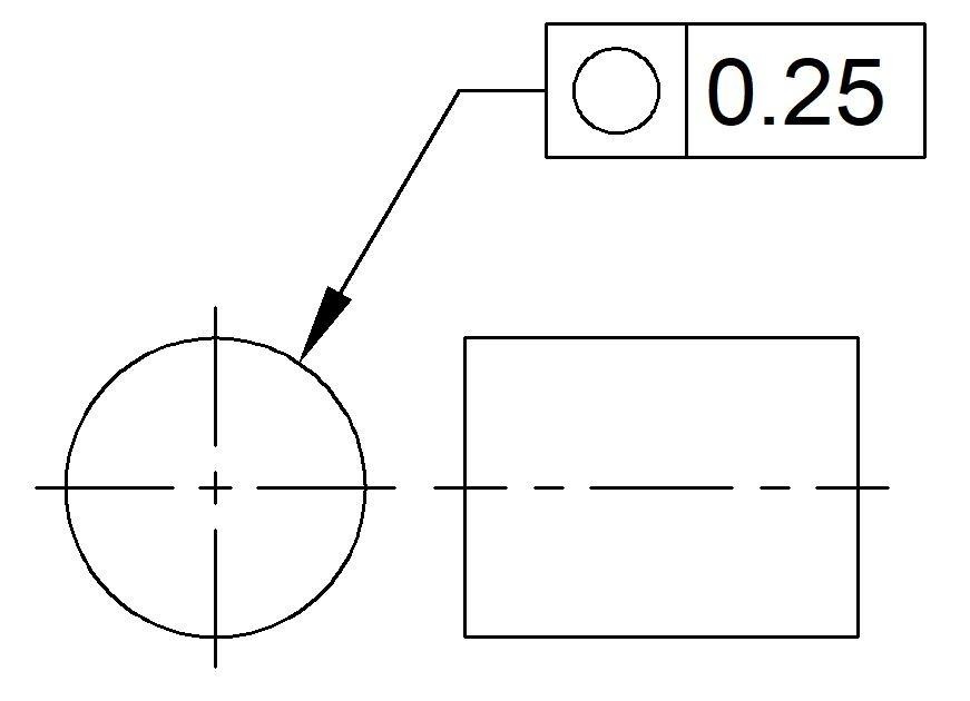
(Engineering Technology) Circularity symbol
Reading the Circularity Symbol and Feature Control Frame
The circularity symbol is a circle in the first compartment of the feature control frame, followed by the tolerance value in the second compartment. Because circularity is a form tolerance, no datum reference is required.
A complete circularity callout looks like this in feature control frame notation:
Compartment 1: circularity symbol (circle)
If the tolerance zone were constrained to a datum axis, the requirement would no longer be circularity alone. Circular runout evaluates surface variation at each cross-section as the part rotates about a datum axis, so it can reflect both out-of-roundness and eccentricity relative to that axis. Circularity isolates the form of each circular element without referencing a datum.
Compartment 2: tolerance value (for example, 0.02). No datum compartment.
The feature control frame is connected to the controlled surface by a leader line or to an extension line of that surface. It should not be attached to the diameter dimension line, which would associate the tolerance with the feature's size rather than its surface form.
Circularity is specified as a form tolerance without a datum reference. MMC and LMC modifiers are not applied to the circularity tolerance value in a standard circularity feature control frame. The callout should follow the applicable ASME Y14.5 or ISO GPS drafting convention.
The Floating Tolerance Zone and the Absence of a Datum
A datum reference in a GD&T callout anchors the tolerance zone to some external reference, a datum plane, a datum axis derived from a bore or shaft. Circularity has no such anchor. The tolerance zone, two concentric circles separated by the tolerance value, is free to position itself wherever it best fits the actual measured cross-section. Under a minimum-zone evaluation, the two concentric circles are positioned to contain the evaluated profile with the smallest possible radial separation. The resulting minimum separation is the roundness deviation for that profile.
The floating tolerance zone allows each circular element to be evaluated independently of a datum axis. Circular runout, by contrast, evaluates surface variation as the part rotates about a datum axis, so its result can reflect both surface form error and the surface's position relative to that axis.
The implication for design: if the functional requirement is that a shaft bore's cross-sections be round, circularity is the correct control. If the functional requirement is that a shaft runs concentrically within a bearing relative to the datum axis, circular runout or total runout is more appropriate, because those controls incorporate the datum relationship that circularity deliberately excludes.
Circularity Tolerance Zone and Example
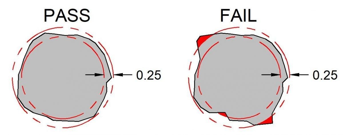
Circularity tolerance examples
How the Circularity Tolerance Zone Works
The circularity tolerance zone at any measured cross-section is an annular region bounded by two coplanar concentric circles. The radial width of that region, the difference between the outer circle radius and the inner circle radius, equals the tolerance value specified in the feature control frame.
For a circular element to conform to a circularity tolerance, its evaluated profile must fit within an annular zone whose radial width does not exceed the specified tolerance. Under the minimum-zone method, the profile is evaluated using the smallest such zone that contains all evaluated points. A minimum-zone width above the specified tolerance indicates nonconformance.
The circularity tolerance is the difference between the radii of the two concentric circles, not the difference between their diameters. For a specified tolerance of 0.02 mm, the outer radius is 0.02 mm greater than the inner radius. A measured roundness deviation of 0.011 mm is within this tolerance, but it does not establish whether the shaft meets its separate diameter limits.
This value represents the allowable roundness deviation of the measured cross-section, not the maximum deviation of every point from a best-fit center. The actual diameter must still satisfy its specified size limits independently.
The two concentric circles defining the tolerance zone lie in the same cross-sectional plane. Circularity does not control taper or changes in surface form along the axis; those conditions require separate controls when they affect function.
Circularity Tolerance Example
Consider a cylindrical shaft with a diameter of 40 mm and a circularity tolerance of 0.015 mm. The drawing callout shows the circularity symbol followed by 0.015 in the feature control frame, with the leader line pointing to the shaft's cylindrical surface.
At any cross-section perpendicular to the axis, the roundness instrument or CMM collects measured points around the circumference. The analysis software determines the minimum zone, the smallest annular ring that contains all those points. If that minimum zone width is 0.011mm at one cross-section and 0.014mm at another, both cross-sections pass the 0.015 circularity tolerance. If a third cross-section requires a zone of 0.017mm, that cross-section fails.
Circularity requirements should reflect how the part functions and how its form will be inspected. JLCCNC can review your CAD file and engineering drawing to assess the specified tolerances before machining.

Precision CNC Machining Service
Upload your CAD files to get an instant CNC machining quote and DFM feedback from JLCCNC engineers.
How Is Circularity Measured?
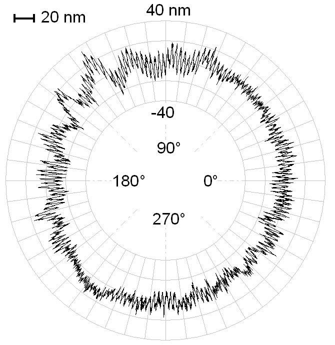
(ResearchGate) Spindle of roundness tester
Roundness Tester and CMM
Dedicated roundness testers are commonly used for high-precision circularity measurement. The instrument rotates the part or probe while recording radial displacement around the circumference. Spindle error motion contributes to measurement uncertainty, but the achievable measurement accuracy also depends on probe performance, calibration, setup, and the evaluation method. For tolerances in the single-micron range, the complete measurement system must be capable of resolving the specified limit with adequate uncertainty.
Roundness software can evaluate the measured profile using different reference-circle methods, including Least Squares Circle (LSC), Minimum Zone Circles (MZC), Minimum Circumscribed Circle (MCC), and Maximum Inscribed Circle (MIC). These methods can produce different numerical results from the same data. MZC directly minimizes the radial separation between two concentric circles and corresponds to the minimum-zone definition of roundness. When conformance is evaluated against that definition, the evaluation method must be consistent with the applicable drawing standard and inspection requirements.
CMM measurement of circularity uses discrete probe points rather than continuous profile data. The number and angular distribution of points determine how well the measured profile captures lobing and other periodic form errors. A sparse point pattern can miss deviations that occur between sampled locations. For this reason, the probing strategy must provide sufficient angular coverage for the expected form characteristics and the required tolerance; a low point count alone cannot establish that the full profile conforms.
Filter settings affect which spatial wavelengths are retained in a roundness profile and therefore influence the reported deviation. The cutoff and UPR (undulations per revolution) settings must be interpreted together with the instrument's filtering convention; changing them can change the measured result. For a bearing journal, the evaluation settings should reflect the functional wavelengths of interest and the applicable inspection specification. ISO 12181 provides guidance on roundness terminology and evaluation.
Manual Checks and Measurement Limitations
Manual circularity checking using a V-block, a surface plate, and a dial indicator is common for in-process screening but provides only an approximation of actual circularity deviation, not a rigorous conformance measurement.
In a V-block check, the part is rotated while a dial indicator records radial variation at the top of the part. The reading is not a direct circularity value because the result depends on the V-block angle, the profile's lobe count, and the contact geometry. Certain lobing patterns can produce a small indicator reading even when the cross-section is not sufficiently round. Use this method for in-process screening, not as a substitute for a suitable roundness measurement when formal conformance must be established.
For tight circularity tolerances, select a calibrated roundness instrument or a suitable CMM based on the required measurement uncertainty. Temperature variation, vibration, probe performance, and measurement repeatability can affect the result. The inspection setup should be capable of reliably distinguishing conforming parts from nonconforming ones at the specified tolerance limit. At that range, thermal expansion, floor vibration, and instrument repeatability all contribute measurement uncertainty that can be a meaningful fraction of the tolerance value.
Circularity vs Cylindricity and Runout
These three controls are frequently confused because they all relate to cylindrical surfaces, and all appear on drawings of shafts and bores. The differences are real and consequential for both drawing interpretation and inspection.
Circularity is a 2D control. It measures one cross-section at a time, in isolation. The zone is two concentric circles in a plane. No datum. No axis. No relationship between cross-sections. It tells you whether individual circular elements are round.
Cylindricity is a 3D control applied to the full cylindrical surface simultaneously. The zone is two coaxial cylinders whose radial separation equals the tolerance value. All points on the surface, not just one cross-section, must fall within that zone. Cylindricity catches roundness error at individual cross-sections (what circularity catches) but also catches taper and axis curvature, because a tapered cylinder or a bent cylinder cannot fit within a tight coaxial cylindrical zone. Cylindricity requires no datum either, because the zone floats to best fit the surface. A cylindricity tolerance controls the entire cylindrical surface within a zone bounded by two coaxial cylinders. When the same tolerance value is used, cylindricity constrains the roundness of the individual circular elements as well as form variation over the full surface. Meeting a circularity tolerance at each cross-section does not, by itself, establish cylindricity conformance. For more on cylindricity and when to use it, see the Cylindricity GD&T guide.
Circular runout and total runout both require a datum axis. Circular runout is the closest relative to circularity, it measures the full indicator movement at a cross-section as the part is rotated about the datum axis. But it combines form error with eccentricity. If a perfectly round cross-section is offset from the datum axis, circular runout detects that offset as indicator variation. Circularity would pass that same cross-section because the cross-section itself is round. A non-round cross-section can produce circular runout even when it is nominally centered on the datum axis, because the indicator responds to the surface's radial variation during rotation. Circularity evaluates the roundness of that cross-section independently of the datum axis. The two controls measure different things and answer different functional questions. Total runout extends the datum-referenced evaluation to the full surface length. For detailed coverage of runout controls, see the GD&T Runout guide.
The practical selection logic: use circularity when the functional concern is that each cross-section is round, and the location of that cross-section relative to a datum is controlled by separate tolerances elsewhere on the drawing. Use cylindricity when the full surface must be cylindrical. Use runout when the surface must run concentrically relative to a specific datum axis during rotation.
| Control | What It Checks | Datum Required? | Use It When |
|---|---|---|---|
| Circularity | Roundness of each cross-section | No | Individual sections must be round. |
| Cylindricity | Form of the entire cylindrical surface, including roundness, taper, and axis curvature | No | The full surface must stay within a cylindrical tolerance zone. |
| Circular Runout | Indicator variation at each cross-section during rotation about a datum axis | Yes | A rotating surface must run true relative to a datum. |
| Total Runout | Indicator variation across the entire surface during rotation about a datum axis | Yes | The full surface must run true along its length. |
When to Specify Circularity
Applications Where Circularity Matters
- Hydraulic and pneumatic cylinders: Keeps bore roundness consistent so seals maintain even contact and prevent leakage.
- Bearing journals: Helps prevent uneven bearing loading, vibration, and premature wear.
- Valve seats and orifices: Maintains consistent sealing and flow area for reliable valve operation and flow measurement.
Specifying Circularity Without Over-Tolerancing
The appropriate circularity tolerance depends on the functional sensitivity of the application, not on a default precision value. Tighter circularity tolerances may require finer machining, cylindrical grinding, honing, or superfinishing rather than turning, and require dedicated roundness inspection rather than diameter measurement.
The starting point for tolerance derivation is the functional analysis: what maximum roundness deviation can the application tolerate? A hydraulic seal's ability to conform to bore non-roundness under pressure gives a maximum circularity deviation. A bearing's published load capacity reduction as a function of journal roundness deviation gives another. Working backward from function produces a tolerance that is as loose as the application allows, not as tight as the machining process can achieve.
Over-specifying circularity is as problematic as under-specifying it. A circularity tolerance tighter than the function requires increases cost, introduces inspection requirements that may exceed available equipment capability, and creates rejection risk for parts that would perform perfectly well in service.
Circularity, Size Limits, and Rule #1
Under ASME Y14.5 Rule #1, a regular feature of size must not violate the boundary of perfect form at maximum material condition (MMC). As the actual local size departs from MMC toward least material condition (LMC), some additional form variation may be possible while the feature remains within its size limits and the MMC boundary. This implicit form control does not replace a separately specified circularity tolerance when the functional requirement is more restrictive.
For a shaft with size limits of 25.000–25.050 mm, the MMC size is 25.050 mm. The 0.050 mm difference between the size limits is not, by itself, a specified circularity tolerance or a universal allowance for roundness deviation. The permissible form variation must be assessed against the actual size and perfect-form boundary requirements.
A separate circularity tolerance is useful when the functional requirement for roundness is more restrictive than the form control provided by the applicable size limits and Rule #1. Its value should be derived from the part's functional requirements and assessed against the other tolerances on the drawing. This is why circularity tolerances should be derived from function, not added reflexively to a drawing without considering what Rule #1 already controls. If the required form control at all sizes is tighter than what Rule #1 permits at LMC, an explicit circularity tolerance is necessary and its value should be the functional requirement.
Under ISO GPS, the default independence principle and any specified envelope requirement must be interpreted according to the applicable standards and drawing indications. ISO 14405-1 addresses dimensional tolerancing of linear sizes, including the envelope requirement for features of size. Designers should verify which size specification applies before deciding whether a separate circularity tolerance is necessary.
Circularity GD&T FAQs
Is Circularity the Same as Roundness?
Yes. Circularity, also called roundness, controls the form of each circular element of a surface. For cylindrical and conical features, these elements are evaluated in planes perpendicular to the axis or spine; for a spherical surface, the applicable standard defines the relevant circular elements. Circularity does not control the feature's overall location or orientation.
Is Circularity Tolerance a Radial or Diametral Value?
Circularity tolerance is the radial separation between two concentric circles, not the difference between their diameters. For example, a circularity tolerance of 0.02 mm means the outer boundary circle has a radius 0.02 mm greater than the inner boundary circle. The difference between their diameters is therefore 0.04 mm.
Can a Part Meet Its Size Limits but Fail a Circularity Requirement?
Yes. Size limits control the permitted dimensions, while circularity controls the form of each circular cross-section. A shaft can measure within its diameter limits but still have lobing or other out-of-roundness that exceeds its circularity tolerance. Both requirements must be met independently when specified.
Does Circularity Control the Axis of a Hole or Shaft?
No. Circularity controls the form of individual cross-sections and does not establish or control the feature's axis. For axis orientation, location or alignment, engineers may need other controls, such as perpendicularity, position or runout, depending on the design requirement.
Precision CNC Machining Service
Professional manufacturing, fast turnaround, and quality assurance.
Conclusion About Circularity GD&T
Circularity is a precise, limited control. It says exactly one thing: each circular cross-section of the controlled surface must be round within the specified radial width. It says nothing about axis location, axis straightness, taper, concentricity, or the relationship between cross-sections, those require separate controls appropriate to each requirement.
Before releasing a drawing, confirm that circularity addresses the actual functional requirement and that the tolerance is consistent with the applicable size limits and other geometric controls. The inspection plan should also define a suitable measurement method, sampling strategy, and evaluation method for the required tolerance.
For a precision-machined part with a critical circularity requirement, JLCCNC can review the drawing to assess the specified tolerance and its manufacturing implications before production.
Keep Learning
Circularity GD&T Explained
Key Takeaways Circularity controls how round each cross-section is on a cylindrical, conical, or spherical surface. Each cross-section is checked separately. Circularity doesn't control taper, axis straightness, or alignment between sections. No datum is needed because circularity controls the shape of the feature itself. The circularity tolerance zone is bounded by two concentric circles whose radial separation equals the specified tolerance. Each circular element must fit within its own zone, evalua......
Press Fit Tolerance: Interference, Charts & Design Guide
Key Takeaways A press fit is an interference fit: the shaft is larger than the hole, and elastic deformation of the mating parts after assembly creates contact pressure that generates the friction holding the joint together. Press fit interference is the difference between the shaft diameter and the hole diameter. Minimum interference uses worst-case dimensions for the smallest overlap. Maximum interference uses worst-case dimensions for the largest overlap. Press fit tolerance is selected based on re......
GD&T Datum: Definition, Types, Symbols, and Datum Reference Frame
Key Takeaways A datum in GD&T is a theoretically exact reference used to locate or orient other features on a part. It is not the physical surface itself. A datum feature is the physical feature identified on the part and used to establish a datum. The datum itself is the theoretically exact geometric reference derived from that feature. Datums become especially important when several features have to work together. A hole pattern, bearing bore, mounting face, or mating surface may need to establish t......
GD&T Runout: Definition, Symbol, Measurement & Tolerance
Key Takeaways Runout limits surface variation while a part rotates around its specified datum axis. The datum feature establishes the axis used for the runout requirement. You compare the full indicator variation during rotation with the tolerance stated on the drawing. Circular runout applies at individual circular sections of the controlled surface. Total runout evaluates the controlled surface across its specified extent. Runout is not a size tolerance, and its value is not determined by the diamet......
GD&T Perpendicularity: Definition, Tolerance & Examples
Key Takeaways Perpendicularity is an orientation control used for a feature specified at 90° to a datum. A surface callout controls the complete surface within two parallel planes set perpendicular to the referenced datum. An axis callout controls the derived axis inside the specified tolerance zone instead of controlling the physical surface directly. Perpendicularity does not establish the location of a feature. A drawing can require another geometric control when position also needs definition. Dat......
Concentricity in GD&T: Definition, Symbol, Tolerance, and Measurement
Key Takeaways Concentricity in legacy ASME GD&T controls the derived median points of a feature relative to a datum axis. It does not simply compare the axes of two fitted cylinders. Check the drawing standard first. Legacy ASME concentricity and ISO concentricity or coaxiality should not be interpreted as equivalent requirements. For the cylindrical example in this guide, the tolerance zone is a cylinder centered on the datum axis. The derived median points of the controlled feature must lie within t......